Tidland Performance Series Automatic Knifeholder - Installation, Operation and Maintenance - Maxcess ...
←
→
Page content transcription
If your browser does not render page correctly, please read the page content below

TIDLAND SLITTING SOLUTIONS

                 Tidland Performance Series
                      Automatic Knifeholder
                 Installation, Operation and Maintenance

                      Class II shown

    EN                                       Class I, II and III

MI 557417 1 AD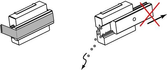
TABLE OF CONTENTS
Knifeholder Safety ................................................................................................................................... 5
Receiving And Unpacking ....................................................................................................................... 5
Knifeholder Component Orientation ........................................................................................................ 6
Blade Guard Options ............................................................................................................................... 7
   360° Blade Guard - Mechanical .......................................................................................................... 7
   Adjusting the guard ............................................................................................................................. 7
   360° Blade Guard - Pneumatic .......................................................................................................... 8
   Function Control Knob ...................................................................................................................... 10
Installation.............................................................................................................................................. 11
   Select Slitting Type ........................................................................................................................... 11
   Determine Setback ............................................................................................................................ 11
   Recommended Web Penetration for Tangential Slitting Applications .............................................. 11
   Prepare to Mount Guide Bar ............................................................................................................. 12
      Determine Space Requirements................................................................................................... 12
      Determine Mounting Dimensions .................................................................................................. 13
          Vertical Mounting Dimension – VMD ........................................................................................ 13
          Horizontal Mounting Dimension – HMD ................................................................................... 13
      Install Guide Bar on Support Beam .............................................................................................. 14
      Methods for Measuring Blade Overlap (For Reference Only) ...................................................... 14
   Mount Knifeholder ............................................................................................................................. 15
      Manual Lock .................................................................................................................................. 15
      Pneumatic Lock ............................................................................................................................ 16
      Adjusting the Gib........................................................................................................................... 16
      Easy Glider Mount (Linear Bearing) ............................................................................................. 18
          Removing the Knifeholder with an Easy Glider Mount ............................................................. 19
   Install Pneumatic System .................................................................................................................. 20
Cant Key ................................................................................................................................................ 22
   Selection............................................................................................................................................ 22
   Orientation ......................................................................................................................................... 22
   Nomenclature .................................................................................................................................... 24
   Reversing the actuator assembly ...................................................................................................... 24
Operation ............................................................................................................................................... 25
   Knifeholder Setup .............................................................................................................................. 25
Manual Lock .......................................................................................................................................... 25
   Manual Lock ...................................................................................................................................... 25
   Pneumatic Lock ................................................................................................................................. 26
Maintenance .......................................................................................................................................... 27
   Preventive ......................................................................................................................................... 27
   Guide Bar Cleanup ............................................................................................................................ 27
   Cant Key O-ring................................................................................................................................. 28
   Blade Cartridge ................................................................................................................................. 28
      Removing/Reinstalling/Reversing ................................................................................................. 28
   Knife Blade ........................................................................................................................................ 29
      Removing/Reinstalling .................................................................................................................. 29
   Knifeholder Dovetail: Replacing the O-ring(s)................................................................................... 30
   360° Blade Guard – Class I............................................................................................................... 31
      Inspecting and Replacing Parts .................................................................................................... 31
Troubleshooting ..................................................................................................................................... 32
   Slit Quality ......................................................................................................................................... 32
   Knifeholder Performance .................................................................................................................. 33
Knifeholder Disassembly ....................................................................................................................... 36
   Control Body Sub-Assembly Identification ........................................................................................ 37
   Guide Bar Mount Assembly .............................................................................................................. 38
      Manual Lock, Class I, II and III ..................................................................................................... 38
      Pneumatic Lock, Class I, II and III ................................................................................................ 39
   Dovetail Assembly, Class I, II and III ................................................................................................ 41
   Upper Body And Piston Assemblies, Class I .................................................................................... 43
   Lower Body Assembly, Class I.......................................................................................................... 44
   Upper/Lower Body and Piston Assemblies, Class II and III .............................................................. 45

www.maxcessintl.com                   Tidland Performance Series Automatic Knifeholder                             MI 557417 1 AD               Page 3
TABLE OF CONTENTS
Function Control Knob Assembly, Class I, II and III.......................................................................... 47
Lubrication and Loctite .......................................................................................................................... 48
Class I ............................................................................................................................................... 48
Class II and III ................................................................................................................................... 49
Air Flow Schematics .............................................................................................................................. 50
Class I ............................................................................................................................................... 50
Class II and III ................................................................................................................................... 51
Knifeholder Parts ................................................................................................................................... 52
Class I ............................................................................................................................................... 52
Automatic Control Body ................................................................................................................ 52
Automatic Blade Cartridge ............................................................................................................ 54
Standard ................................................................................................................................... 55
w/ Pneumatic 360° Blade Guard .............................................................................................. 56
Class II and III ................................................................................................................................... 58
Automatic Control Body ................................................................................................................ 58
Automatic Blade Cartridge ............................................................................................................ 60
Standard ................................................................................................................................... 60
w/ Pneumatic 360° Blade Guard .............................................................................................. 62
w/ Mechanical 360° Blade Guard ............................................................................................. 64
Guide Bar Mount Assemblies............................................................................................................ 66
Manual Lock, Class I, II and III ..................................................................................................... 66
Pneumatic Lock ............................................................................................................................ 67
Class I ....................................................................................................................................... 67
Class II and III ........................................................................................................................... 68
Duraglide ....................................................................................................................................... 69
Class II and III ........................................................................................................................... 69
Easy Glider Mount, Class I, II and III ............................................................................................ 70
Cartridge to Control Body Compatibility Chart ...................................................................................... 71
Blade Grinding and Finishing ................................................................................................................ 72
www.maxcessintl.com Tidland Performance Series Automatic Knifeholder MI 557417 1 AD Page 4KNIFEHOLDER SAFETY
Important!
The Tidland Performance Series Knifeholder intended use is to produce a slit with a driven anvil
system. There is no other intended purpose.
Read and understand all instructions before operating the knifeholder. Failure to follow instructions
may cause the knifeholder to function incorrectly and can cause serious injury.
The knifeholder contains spring-loaded components. While operating the knifeholder, follow all
existing plant safety instructions and/or requirements.
Tidland recommends wearing stainless steel protective gloves when changing or removing the
knife blade.
Sharp knives can cause serious injury. Do not put hands in machines.
Compliance with federal, state, and local safety regulations is your responsibility. Be familiar with
them and always work safely.
Receiving And Unpacking
Handle and unpack the equipment carefully. Upon arrival, check the shipment against the packing
list.
Promptly report to the carrier any damaged equipment.
Equipment that will not be installed immediately should be stored in a clean, dry location.
Be careful to prevent moisture, dust, and dirt from accumulating in storage and installation areas.
www.maxcessintl.com Tidland Performance Series Automatic Knifeholder MI 557417 1 AD Page 5KNIFEHOLDER COMPONENT ORIENTATION
1 Depth Control Knob
Increase blade cartridge stroke – rotate counterclockwise
Decrease blade cartridge stroke – rotate clockwise
2 Function Control Knob (p. 10)
yellow arrow – setup (to position knifeholder)
extends knifeholder blade cartridge for knifeholder
positioning and locking to guide bar
red arrow – retract (non-operating position)
completely retracts knifeholder blade cartridge
green arrow – run (operating position)
extends knifeholder blade cartridge to Depth Control
Knob setting
Do not operate knifeholder in the setup position.
3 Knifeholder Control Body
4 Cant Key (blade cartridge angle control)
5 Knifeholder Bellows (prevents foreign matter from entering
knifeholder)
6 Safety Lock Pin (shown in locked position)
7 Dovetail (control body to blade cartridge interface)
8 Lock/Unlock Lever (shown in locked position)
9 Blade Cartridge (shown w/ blade guard safety attachment)
10 Knife Blade
11 Guide Bar Mount Assembly (not shown)
12 Air Supply Hose (control body and cartridge)
Options:
Class I 360° Blade Guard cartridge; see page 7.
Class II and III 360° Swing Guard Kit; see page 7. Class II shown
SPECIFICATIONS
Actual speed is dependent on application and material
Class I Class II Class III
Blade Diameter 3.54" (90 mm) * 5.91" (150 mm) 7.87" (200 mm)
Minimum Slit Width 1.0" (25.4 mm) ** 2.0" (50.8 mm) 3.0" (76.2 mm)
Designed Maximum Speed* 3500 fpm (1,067 mpm) 5500 fpm (1,677 mpm) 10,000 fpm (3,049 mpm)
Recommended Operating Air
60-75 psi (4.1-5.2 bar) 60-75 psi (4.1-5.2 bar) 60-75 psi (4.1-5.2 bar)
Pressure (max. 100 psi)
* If using the Class I 360° Blade Guard cartridge, the minimum blade diameter required to remain CE
compliant is 84 mm. CE requirement isKNIFEHOLDER BLADE GUARD OPTIONS
360° Blade Guard Cartridge - Mechanical
The reversible blade guard covers the blade when the knifeholder is retracted during non-operation
and handling.
The guard is held in place by a bracket installed on the guide bar mount and is actuated by the
extension of the knifeholder.
The actuator assembly is reversible; it can be moved to the other side of the blade guard strut if you
need to change the cut side. See page 24.
Modified blade guards are available for strip blades and wide rim blades.
When the blade cartridge is retracted, the blade is guarded. When the blade cartridge extends, the
blade is unguarded.
Guarded Unguarded
Knifeholder retracted Knifeholder extended
Adjusting the blade guard
To adjust the guard for a closer fit to the knife blade, turn
the M5 adjustment set screw (1) clockwise until the guard
touches the blade, and then back off one-quarter turn.
The knife blade should spin freely and smoothly on the
blade hub and not rub on the guard.
www.maxcessintl.com Tidland Performance Series Automatic Knifeholder MI 557417 1 AD Page 7KNIFEHOLDER BLADE GUARD OPTIONS
360° Blade Guard Cartridge - Pneumatic
Class I – 718312
The guard protects the blade during handling and non-operation when air is not supplied to the
knifeholder. The guard is to prevent bodily injury during handling or if the product is dropped.
The guard consists of the guard flap, a pneumatic cylinder, a wedge cam, cylinder mount and a return
spring that keeps the guard closed when air is not supplied to the cylinder. When air is applied, the
cylinder retracts and the flap exposes the blade for the slitting operation. The flap and knifeholder
downstroke operation is staged so that the flap never interferes with the anvil ring.
Guarded Unguarded
During transport, installation During slitting operation
or maintenance
When air is on and the
When air is off, or function
knifeholder function control
control knob is in the red
knob is turned to the setup
(retract) position, the
(yellow) or engage (green)
actuator is extended (1) and
position, the actuator retracts
the blade guard pivots into
(3) and the blade guard pivots
the guarded position (2) as
into the unguarded position
the cartridge retracts.
(4) as the cartridge extends.
To adjust the flap for a closer
fit to the knife blade, turn set
screw (1) clockwise until the
guard flap (2) just touches the
knife blade (3), and then back
off one-quarter turn.
The knife blade should spin
freely and smoothly on the
bearing hub and not rub
against the guard flap.
www.maxcessintl.com Tidland Performance Series Automatic Knifeholder MI 557417 1 AD Page 8KNIFEHOLDER BLADE GUARD OPTIONS
360° Blade Guard Cartridge - Pneumatic
Class II – 548274
Class III – 548275
This guard does not protect against bodily injury during handling and transport.
Guarded (1) Unguarded (2)
Extending the Blade Guard
The blade guard is actuated automatically via an internal air circuit interface between the
knifeholder and the cartridge.
The cartridge extends and the blade guard retracts as the supply air is distributed at the setup
knob in either the GREEN (RUN) or YELLOW (SETUP) positions.
When the supply air is turned off at the setup knob RED (RETRACT) position, or at a gang manifold
shut off valve, the cartridge retracts and the blade guard extends out of the cartridge.
Flow Control Valve
The flow control valve assembly (3) provides a time delay between cartridge retraction and the blade
guard extension. Increase the delay by turning the flow control knob clockwise.
www.maxcessintl.com Tidland Performance Series Automatic Knifeholder MI 557417 1 AD Page 9FUNCTION CONTROL KNOB
COLOR POSITION FUNCTION
Extends blade cartridge, and then allows half of the
available side stroke.
Yellow Arrow Use when positioning knifeholder blade to anvil rings
before lockup to guide bar.
SETUP
Reverses sidestroke movement, then retracts blade cartridge.
Use when knifeholder is not in operation.
Use when adjusting depth control knob for overlap.
Red Arrow
Use when traversing knifeholder with retracted blade cartridge
to new slit position.
STOP
(RETRACT)
Extends blade cartridge, then allows full sidestroke.
Green Arrow Use when operating knifeholder.
RUN
www.maxcessintl.com Tidland Performance Series Automatic Knifeholder MI 557417 1 AD Page 10INSTALLATION
Select Slitting Type
TANGENT WRAP
Knifeholder axis should be 90° to web path. Knifeholder axis should bisect the wrap angle.
Tangent slitting requires knifeholder setback. Knifeholder setback is not required.
Determine Setback
Recommended Knifeholder Setback (For Tangent Slitting Only)
For best slit result, the web must be in contact with the anvil knife ring at the cut point. If the web
contacts the top blade ahead of the cut point, the material will tear instead of slitting cleanly.
Geometry shown is based on medium weight kraft paper. For assistance with other web materials, call
Tidland Customer Service, 1-800-426-1000.
Recommended Setback
for Paper Based Products
Class I 1/8" 3.18 mm
Class II 1/4" 6.35 mm
Class III 3/8" 9.53 mm
Recommended Web Penetration for
Tangential Slitting Applications
To maximize web stability at the cut point, Tidland recommends web
penetration by the anvil ring of .015"-.060". Check this measurement
by laying a straight edge across the idler rolls to represent the web.
Measure how far the anvil ring "penetrates" the plane created by the
straight edge.
Thicker web materials require more penetration, while thinner or
sensitive materials may require no penetration. Call Tidland
Customer Service for assistance. 1-800-426-1000
www.maxcessintl.com Tidland Performance Series Automatic Knifeholder MI 557417 1 AD Page 11INSTALLATION
Prepare to Mount Guide Bar
Determine Space Requirements
Standard guide bar shown; the Duraglide mounting option is interchangeable with
this.
Does not include
width of bellows.
Class II shown
Inches A B C D E F G H I J K L M N O P Q R
Class I 4.74 2.46 0.05 3.86 3.61 2.89 1.04 1.84 4.85 6.62 0.63 3.92 3.54 0.945 0.12 0.19 0.05 11.51
Class II 5.72 2.94 0.03 4.55 4.41 3.26 1.28 2.34 6.79 9.74 1.00 6.33 5.91 1.75 0.16 0.38 0.08 15.57
Class III 6.47 3.46 0.04 4.73 4.56 3.05 1.28 2.34 7.83 11.77 1.00 8.35 7.87 2.76 0.24 0.77 0.12 17.78
Millimeters A B C D E F G H I J K L M N O P Q R
Class I 120.5 62.5 1.4 97.9 91.7 73.4 26.4 46.8 123.2 168.1 16.0 100.0 90 24.0 3.0 4.8 1.3 292.4
Class II 145.3 75.0 0.7 115.5 112 82.9 32.5 59.5 172.3 247.4 25.4 161.0 150 44.5 4.1 9.6 2.0 395.4
Class III 164.3 87.9 1.0 120 115.7 77.5 32.5 59.5 198.8 298.9 25.4 212.0 200 70.0 6.1 19.7 3.0 451.6
Note: Dimensions are nominal and represent the average of assembled units. These are not the specifications of individual parts
nor do they reflect manufacturing tolerances.
``
www.maxcessintl.com Tidland Performance Series Automatic Knifeholder MI 557417 1 AD Page 12INSTALLATION
Determine Mounting Dimensions
Vertical Mounting Dimension – VMD
The distance from the centerline of the guide bar mounting holes to the anvil roll or ring O.D.
and perpendicular to the web path
Horizontal Mounting Dimension – HMD
The distance from the support beam face (guide bar mounting surface) to the vertical centerline
through the center of the anvil ring.
VMD (Vertical Mounting Dimension)
Tangent & Wrap Slitting
Class I 6-29/32" (175.4 mm)
Class II 10-3/16" (258.8 mm)
Class III 12-1/4" (311.2 mm)
These dimensions reserve approximately 1/2 of blade cartridge stroke for blade regrinding.
HMD (Horizontal Mounting Dimension)
Tangent Slitting * Wrap Slitting **
'A' Web Path 'B' Web Path 'A' or 'B' Web Path
Class I 2-9/16" (65.1 mm) 2-5/16" (58.7 mm) 2-7/16" (61.9 mm)
Class II 3-7/32" (81.8 mm) 2-23/32" (69.1 mm) 2-31/32" (75.4 mm)
Class III 3-27/32" (97.6 mm) 3-3/32" (78.6 mm) 3-15/32" (88.1 mm)
* These dimensions will result in setbacks as listed in Recommended Setback Distance on page 11.
** These dimensions provide no setback.
www.maxcessintl.com Tidland Performance Series Automatic Knifeholder MI 557417 1 AD Page 13INSTALLATION
Install Guide Bar on Support Beam (standard guide bar shown)
- The guide bar must be straight within 0.010” (0.25 mm) on a rigid and vibration-free support.
- Avoid scratches or dents to the guide bar during installation.
1. Determine the center-to-center distance between the mounting bolt holes (X) on the guide bar.
Standard pre-drilled dimension (X) is 12" (304.80 mm).
Drill and tap support beam for pre-drilled guide bar: 3/8"-16NC holes
DuraGlide mounting option: Use only low-head socket head bolts to mount guide bar.
2. Before transferring dimension (X) onto the support beam, make sure there will be enough free space
at one end of the beam for knifeholder installation and removal once the guide bar is mounted.
Minimum Space Recommended for Removal
(Free Space)
Class I 2" (50.8 mm)
Class II 3" (76.2 mm)
Class III 4" (101.6 mm)
Methods for Measuring Blade Overlap (For Reference Only)
See pages 24-26 for knifeholder setup instructions.
Method 1 Method 2
Measure blade overlap directly along the common Measure the chord of the intersection between
centerline of the knife blade and anvil ring. the knife blade and anvil ring.
www.maxcessintl.com Tidland Performance Series Automatic Knifeholder MI 557417 1 AD Page 14INSTALLATION
Mount Knifeholder – Standard Guide Bar
Manual Lock
WARNING! Blades are sharp!
Avoid injury—Tidland recommends wearing steel protective gloves when handling blades.
Installation at End of Guide Bar (Recommended)
1. Turn the brake knob counterclockwise enough to
allow the brake shoe to be manually retracted into the
mount. (Push the brake shoe up into mount if
extended out.)
2. Align the mount with the guide bar end.
3. Slide the knifeholder onto guide bar. If clearance is
restricted, remove blade cartridge (p. 28).
4. See Adjusting the Gib below, if necessary.
5. Turn the brake knob clockwise to secure the
knifeholder in position.
6. Turn the set up knob to the red (retract) position and
connect the air supply line.
Installation at Center of Guide Bar
1. Remove blade cartridge from the control body (p. 28).
2. Remove the two socket head cap screws that secure
the gib to the mount; remove the gib.
3. Turn the brake knob counterclockwise to fully retract
the brake shoe into the mount. (Push the brake shoe
up into mount if extended out.)
4. Place the control body onto the guide bar.
5. While holding the control body securely in place,
reinstall the gib. Align the gib socket head cap screw
holes with the holes in the mount assembly.
6. Install and tighten the socket head cap screws to secure the gib in place.
Torque: Class I — 2.1 ft·lbs (2.85 Nm) Class II and III — 4.3 ft·lbs (5.83 Nm)
7. Turn the brake knob clockwise to secure the knifeholder in position.
8. Reinstall the blade cartridge onto the control body (p. 28).
9. Turn the set up knob to red (retract) position and connect the air supply line.
Adjusting the Gib
1. Loosen the two gib socket head cap screws by 1//4 turn.
2. Tighten or loosen the gib set screw to achieve a secure fit and smooth knifeholder traverse action
on the guide bar. Recommended: 1/4 turn per adjustment.
3. Ensure that side of gib are parallel to sides of knifeholder when adjusting and tightening the two
gib socket head cap screws.
Torque: Class I — 2.1 ft·lbs (2.85 Nm) Class II and III — 4.3 ft·lbs (5.83 Nm)
4. Re-adjust as necessary.
www.maxcessintl.com Tidland Performance Series Automatic Knifeholder MI 557417 1 AD Page 15INSTALLATION
Mount Knifeholder – Standard Guide Bar
Pneumatic Lock
WARNING! Blades are sharp!
Avoid injury—Tidland recommends wearing steel protective gloves when handling blades.
Installation at End of Guide Bar (Recommended)
1. Align the mount and traverse gear with the guide bar end
and gear rack.
2. Make sure the traverse/brake knob is in the unlocked (up)
position. (Push the brake shoe up into the mount if
extended out.)
3. Slide the knifeholder onto the guide bar. If clearance is
restricted, remove the blade cartridge (p. 28).
4. Turn the traverse knob to move the knifeholder in position.
See Adjusting the Gib below, if necessary.
5. Turn the set up knob to the red (retract) position and
connect the air supply line.
6. Push down the traverse/brake knob to lock the knifeholder
to the guide bar. Pull up the traverse/brake knob to unlock
and traverse the knifeholder.
Installation at Center of Guide Bar
1. Remove the blade cartridge from the control body (p. 28).
2. Remove the two socket head cap screws that secure the
gib to the mount; remove the gib.
3. Place the control body onto the guide bar.
4. While holding the control body securely in place, reinstall
the gib and align the gib socket head cap screw holes with
the holes in the mount.
5. Install and tighten the socket head cap screws to secure
the gib in place.
Torque: Class I — 2.1 ft·lbs (2.85 Nm) Class II and III — 4.3 ft·lbs (5.83 Nm)
6. Turn the traverse knob to move the knifeholder into position.
7. Reinstall the blade cartridge onto the control body (p. 28).
8. Turn the set up knob to red (retract) position and connect the air supply line.
9. Push down the traverse/brake knob to lock the knifeholder to the guide bar.
Adjusting the Gib
1. Loosen the two gib socket head cap screws by 1/4 turn.
2. Tighten or loosen the gib set screw to achieve a secure fit and smooth knifeholder traverse action
on the guide bar. Recommended: 1/4 turn per adjustment.
3. Ensure that the sides of gib are parallel to sides of knifeholder when adjusting and tightening the
two gib socket head cap screws.
Torque: Class I — 2.1 ft·lbs (2.85 Nm) Class II and III — 4.3 ft·lbs (5.83 Nm)
4. Re-adjust as necessary.
www.maxcessintl.com Tidland Performance Series Automatic Knifeholder MI 557417 1 AD Page 16INSTALLATION
Mount Knifeholder – DuraGlide Guide Bar
WARNING! Blades are sharp!
Avoid injury—Tidland recommends wearing steel protective gloves when handling blades.
Installation at End of Guide Bar
It is not possible to install the knifeholders at the center of the guide bar; you must install them at
either end.
Pneumatic Lock
1. Make sure that the bearings on the knifeholder
mount are tight.
2. Align the knifeholder at the end of the guide
bar and slide the knifeholder onto the guide
bar. If clearance is restricted, remove the blade
cartridge.
3. Turn the set up knob to the red (retract)
position and connect the air supply line.
4. Push down the brake knob to lock the
knifeholder to the guide bar. Pull up the brake
knob to unlock and move the knifeholder along
the guide bar.
Manual Lock
1. Turn the brake knob counterclockwise enough
to allow the brake shoe to be manually
retracted (Push the brake shoe up into mount if
extended out.)
2. Align the knifeholder at the end of the guide
bar and slide the knifeholder onto the guide
bar. If clearance is restricted, remove the blade
cartridge.
1 DuraGlide guide bar
3. Turn the brake knob clockwise to secure the
knifeholder in position. 2 DuraGlide bearings
4. Turn the set up knob to the red (retract) 3 Backplate
position and connect the air supply line. 4 Lock knob
5 Function control knob
If bearings bind on the guide bar
Knifeholder movement should be smooth along the length of the guide bar. If the bearings drag or
catch, check the guide bar for debris and wipe it clean. Use a light coating of dry lubricant spray; let
dry and wipe off.
Serious binding indicates that the guide bar may be damaged or may not have been installed per
the specifications on page 14.
www.maxcessintl.com Tidland Performance Series Automatic Knifeholder MI 557417 1 AD Page 17INSTALLATION
Easy Glider Mount (Linear Bearing)
READ FIRST
Do not remove the factory-installed short rail section
from the linear rail.
This rail section must be used to install the
knifeholder onto the guide bar rail.
Failure to use this rail section when installing the
knifeholder may result in bearing damage and void
bearing warranty.
Safety Recommendation
Remove blade cartridge from knifeholder before handling.
Installing the Knifeholder on the Linear Bearing Rail
1. Choose at which end of the guide bar the
knifeholders will be mounted.
2. At the mounting end only, locate and remove the
#10-32 end stop screw on the face of the guide bar.
3. Do not remove the short rail from the knifeholder
bearing.
4. Turn the brake knob counterclockwise to unlock.
5. Push the brake shoe up into the back plate if
protruding.
6. Install the knifeholder:
7. Hold the knifeholder and short rail section together.
Carefully place the rail section into the keyway on
the guide bar.
8. Align the short rail section with the fixed bearing rail
on the guide bar.
9. Slide the knifeholder onto fixed bearing rail.
10. Remove short section of bearing rail from the guide
bar. Note: Keep the short rail for future
maintenance and knifeholder removal.
11. Repeat Steps 4-9 until all knifeholders are installed
on the guide bar.
12. After all knifeholders are installed, reinstall the #10-32 screws in the end stop.
13. Reinstall blade cartridges on knifeholders.
14. Turn the function control knob to red (retract) position on all knifeholders.
www.maxcessintl.com Tidland Performance Series Automatic Knifeholder MI 557417 1 AD Page 18INSTALLATION
Removing the Knifeholder with Easy Glider Mount (Linear Bearing)
Safety Recommendation
Remove blade cartridge from knifeholder before handling.
1. Remove the blade cartridge.
2. Choose at which end of the guide bar the
knifeholder will be removed; move the
knifeholder just to the end of the fixed rail
on the guide bar.
3. Locate and remove the #10-32 screw
from the end stop on the face of the
guide bar.
4. In the space at the end of the guide bar,
align the short piece of rail (received with
each knifeholder bearing mount) with the
fixed rail and transfer the knifeholder from
the fixed rail to the short rail.
5. Hold the knifeholder and the short rail
together and carefully remove them from
the guide bar. Do not remove the short
rail from the knifeholder bearing mount.
You will need it to reinstall the knifeholder
on the guide bar.
TIP
Secure the short rail to the linear
bearing with a small piece of tape to
retain the bearing balls during
maintenance.
www.maxcessintl.com Tidland Performance Series Automatic Knifeholder MI 557417 1 AD Page 19INSTALLATION
Install Pneumatic System
Tidland recommends the use of a filtered and regulated pneumatic system to prevent airborne oil or
water from contaminating the knifeholders and to provide the correct air pressure to the knifeholders to
help achieve quality slitting.
The pneumatic system* includes:
A) 3/8" (9.52mm) supply air lines
B) 5 micron air filter/pressure regulator with gauge
(0-100 psi or 0-6.9 bar)
C) Coalescing filter
D) 3-way manual valve with muffler
E) Quick exhaust valve with muffler
(Quick disconnect fittings and air manifolds are also available from Tidland.)
Recommended operating air pressure: 60-75 psi (4.1-5.2 bar).
Note: This is a guideline for knifeholder setup – the actual air pressure is dependent upon
application and material.
Maximum operating air pressure: 100 psi
Note: Internal hoses may rupture if maximum air pressure is exceeded.
Clean, non-lubricated, dry air is required for optimal performance of the knifeholder.
Before operating, make sure that the air lines from the air manifold to the knifeholder are securely
connected.
Single manifold system – Tidland PN 520984
Dual manifold system – Tidland PN 520985
www.maxcessintl.com Tidland Performance Series Automatic Knifeholder MI 557417 1 AD Page 20KNIFEHOLDER SIDE FORCE / DOWN FORCE OUTPUT CHART Knifeholder loads will vary slightly from averages shown. www.maxcessintl.com Tidland Performance Series Automatic Knifeholder MI 557417 1 AD Page 21
CANT KEY Selection Cant Angle Options: 0°, 1/4°, 1/2°, 1° The angle is engraved in the key. The cant key label color indicates the web path direction as determined at the time of sale. 'A' Web Path = RED label 'B' Web Path = BLUE label If the web path needs to be reversed at any time, Tidland recommends replacing the cant key label with one of the correct color. Cant Key Orientation The arrow on the cant key label should: point to the nip point (blade contact side) of the anvil ring (see page 23). point in the same direction as the arrow on the blade cartridge. Arrows pointing in opposite directions indicate that: the nip point will not be closed, resulting in poor slit quality, and either the cant key orientation needs to be reversed, or the cartridge orientation (left or right hand) must be changed. To change the cant key orientation, pull the key all the way out of the control body, rotate it 180° and reinstall the key, pushing it firmly into the control body. Cant Key Maintenance (p.28) www.maxcessintl.com Tidland Performance Series Automatic Knifeholder MI 557417 1 AD Page 22
CANT KEY
Cant Key Orientation (continued)
"A" Web Path
Web moves from control side of
knifeholder toward the guide bar mount.
Cant key label is RED.
Cant key arrow points toward the THIN
side of the cant key.
Blade cartridge arrow points to the nip
point (contact side of anvil ring.)
"B" Web Path
Web moves from the guide bar mount
toward the control side of knifeholder.
Cant key label is BLUE.
Cant key arrow points toward the
THICK side of the cant key.
Blade cartridge arrow points to the nip
point (contact side of anvil ring.)
www.maxcessintl.com Tidland Performance Series Automatic Knifeholder MI 557417 1 AD Page 23OPERATION
360° Blade Guard Cartridge
1 Guide bar mount
2 Bracket (stationary)
3 Actuator assembly (reversible)
4 Actuator assembly release pin
5 Adjustment screw
6 Blade guard
Reversing the blade guard Remove the blade cartridge from the knifeholder
actuator assembly before reversing the actuator assembly.
www.maxcessintl.com Tidland Performance Series Automatic Knifeholder MI 557417 1 AD Page 24OPERATION
Knifeholder Setup
Manual Lock
Ensure that
anvil rings are in a pre-selected slit position.
blade cartridge is securely locked to control body.
air supply is attached.
1. Turn the function control knob to the red (retract) position.
2. Loosen the brake knob. Knifeholder is ready to move.
3. For first time operation or for use with a new full diameter
blade, adjust the depth control knob to one-half its total
stroke.
4. Manually slide the knifeholder along the guide bar to place
knife blade within 1/4" of the anvil ring at the new slit position.
Caution! Ensure that knife blade is not directly over the anvil
ring in order to prevent damage by collision when blade
cartridge is extended in Step 5.
5. Turn the function control knob to the yellow (setup) position to
extend the knifeholder blade cartridge.
6. Manually slide the knifeholder along the guide bar until the
knife blade and the anvil ring just touch.
7. Tighten the brake knob to lock the knifeholder to the guide bar
(knife blade and anvil ring should be touching).
8. Observe overlap of knife blade and anvil ring. See Measuring
Blade Overlap (p. 14).
9. If the overlap is correct —0.030" (0.8mm)— the knifeholder is
ready to slit: go to Step 13. If the overlap is incorrect, go to Step 10 to make adjustments. (Some
web products may require more or less overlap.)
10. Turn the function control knob to the red (retract) position. Note: All depth control adjustments
must be made in the red (retract) position.
11. To increase the overlap, turn the depth control knob counterclockwise.
To decrease the overlap, turn the knob clockwise.
Note: One click increases or decreases the overlap .004" (0.1 mm).
One complete turn increases or decreases the overlap .040" (1.0 mm).
DO NOT SCREW the depth control knob all the way into the body. There will be no travel
during cartridge extension.
12. When overlap is correct, turn function control knob to the red (retract) position, if necessary, to
retract the blade cartridge, then turn it to the green (run) position, extending the blade cartridge.
Caution! If the blade cartridge is not retracted before turning to the green (run) position, it will not
function as designed and may result in poor slit quality.
13. The knifeholder is ready to slit.
Keep knifeholders and blade cartridges free of dust and debris during operation.
Maintenance schedule is dependent upon machine environment.
www.maxcessintl.com Tidland Performance Series Automatic Knifeholder MI 557417 1 AD Page 25OPERATION
Knifeholder Setup
Pneumatic Lock
Ensure that
anvil rings are in a pre-selected slit position.
blade cartridge is securely locked to control body.
air supply is attached.
Note: The Duraglide and Easy Glider mounts do not use the gear rack
traverse function. Use the knob only to release or lock the brake, and
then slide the knifeholder manually along the guide bar.
1. Turn the function control knob to the red (retract) position.
2. Lift the traverse/brake knob. Knifeholder is ready to move.
3. For first time operation or for use with a new full diameter blade,
adjust the depth control knob to one-half its total stroke.
4. Manually slide the knifeholder along the guide bar to place knife
blade within 1/4" of the anvil ring at the new slit position.
Caution! Ensure that knife blade is not directly over the anvil ring in
order to prevent damage by collision when blade cartridge is
extended in Step 5.
5. Turn the function control knob to the yellow (setup) position to extend
the blade cartridge.
6. Turn the traverse/brake knob to move the knifeholder along the
guide bar until the knife blade and the anvil ring just touch.
7. Press down on the traverse/brake knob to lock the knifeholder to the
guide bar. Knife blade and anvil ring should be touching.
8. Observe overlap of knife blade and anvil ring. See Setting Blade Overlap (p. 14).
9. If the overlap is correct —0.030" (0.8mm)— the knifeholder is ready to slit: go to Step 13. If the
overlap is incorrect, go to
Step 10 to make adjustments. (Some web products may require more or less overlap.)
10. Turn the function control knob to the red (retract) position. Note: All depth control adjustments
must be made in the red (retract) position.
11. To increase the overlap, turn the depth control knob counterclockwise.
12. To decrease the overlap, turn the knob clockwise.
Note: One click increases or decreases the overlap .004" (0.1 mm).
One complete turn increases or decreases the overlap .040" (1.0 mm).
DO NOT SCREW the depth control knob all the way into the body. There will be no travel
during cartridge extension.
Caution! If the blade cartridge is not retracted before turning to the green (run) position, it will not
function as designed and may result in poor slit quality.
13. The knifeholder is ready to slit.
Keep knifeholders and blade cartridges free of dust and debris during operation.
Maintenance schedule is dependent upon machine environment.
www.maxcessintl.com Tidland Performance Series Automatic Knifeholder MI 557417 1 AD Page 26MAINTENANCE – PREVENTIVE
Preventive
Keep anvil rings and knifeholder blades clean and balanced.
Do not use oil lubricants in knifeholder. Oil lubricants may cause the knifeholder to function
improperly. Use only those lubricants recommended in this publication.
Daily
Keep all knifeholders clean of debris.
Check air pressure to the knifeholders: Clean, dry, non-lubricated air is essential for optimal
knifeholder performance.
Check for air leaks at the knifeholder and manifold.
Note: DO NOT IMMERSE knifeholders in solvents. Wipe the outer surfaces with a clean, dry rag.
Blades are sharp! Can cause serious injury.
Repairs should be performed by trained repair personnel only.
Weekly
Check knifeholder air pressure. Knifeholder air pressure requirements:
1½ cfm @ 60-90 psi (4.1-6.2 bar).
Blow down the blade cartridge to remove dust build up.
Check hose connections to the knifeholders for leaks or cracks.
Inspect control body dovetail assembly o-rings. Replace if damaged or missing.
Check blade cartridge half stroke function.
Monthly
Check adjustment of gib to the guide bar for minimal clearance between knifeholder mount
and guide bar.
Clean all surfaces of the control body and blade cartridge.
Inspect bellows for tears around dovetail mount. Replace if necessary.
Bi-Yearly
Clean and inspect blade cartridge bearings for looseness.
Remove depth control knob and inspect for dust build up, if applicable.
Remove cant key and inspect for excessive wear. Replace if necessary.
Check cant key o-ring for damage. Replace if necessary.
Guide Bar Cleanup
Periodically wipe the guide bar clean and lubricate with a silicone dry film lubricant. Tidland
Corporation recommends using Dow Corning 557 Silicone Dry Film Lubrication to assure smoother
knifeholder movement. Spray the guide bar, let dry, and then wipe the guide bar again.
www.maxcessintl.com Tidland Performance Series Automatic Knifeholder MI 557417 1 AD Page 27MAINTENANCE Cant Key O-ring The cant key must remain tight in the knifeholder body. If the cant key becomes loose in the body or if cracks in the o-ring are visible, replace the o-ring. Replacing the O-ring 1. Pull the o-ring straight out from the control body. 2. Remove o-ring from the cant key. Caution! Do not nick or otherwise damage o-ring groove edges when removing o-ring. 3. Using Parker Super O-Lube, lubricate the new o-ring and the cant key o-ring groove. 4. Install new o-ring into the cant key o-ring groove. 5. Select arrow orientation as described in Cant Key Orientation on page 22. 6. Push the cant key straight into the knifeholder body. Blade Cartridge Removing the Cartridge 1. Turn the function control knob to the red (retract) position. 2. Pull the lock/unlock lever up to unlock the blade cartridge. 3. Press and hold down the safety lock pin and slide the blade cartridge off the control body. Reinstalling the Cartridge 1. Slide the blade cartridge onto the control body. 2. The safety lock pin will 'snap' in place when the blade cartridge is in the correct position. 3. Pull the lock/unlock lever down to lock the blade cartridge to the control body. 4. Confirm that the arrow on the blade cartridge is pointing in the same direction as the arrow on the cant key. Reversing the Cartridge 1. Follow Steps 1 through 3 above to remove the blade cartridge. 2. Install the blade cartridge onto the control body in the opposite direction from the way it was removed. The safety lock pin will 'snap' in place when the blade cartridge is in the correct position. 3. Pull the lock/unlock lever down to lock the blade cartridge to the control body. 4. Remove the cant key and replace it back in the control body, making sure that the arrow on the cant key is pointing in the same direction as the arrow on the blade cartridge. www.maxcessintl.com Tidland Performance Series Automatic Knifeholder MI 557417 1 AD Page 28
MAINTENANCE

Knife Blade

          Blades are sharp! Can cause serious injury.
          Repairs should be performed by trained repair personnel only.

For ease and safety during blade maintenance, Tidland recommends the use of the Tidland
Bench Fixture.

Removing
1. Remove the blade cartridge (p. 28)
2. Press and hold the blade lock pin and rotate the blade hub until it stops.
3. Loosen the three blade clamp screws.
4. Rotate the blade clamp counterclockwise and slide it off the blade hub when the clearance holes
   are aligned with the blade clamp screw heads.
5. Remove the knife blade.

Reinstalling
1. Make sure the blade cartridge is held securely.
2. Clean the blade hub surface where the blade mounts to assure correct fit of the blade and to help
   prevent blade runout (wobble).
3. Replace the knife blade with the slitting edge toward the strut.
4. Replace the blade clamp onto the blade hub. Rotate the blade clamp clockwise until the counter-
   bored areas of the clearance holes are under the blade clamp screw heads.
5. Tighten the three Grade 8.8 blade clamp screws to the appropriate torque value:
             Class I .............................. 9 in·lbs (1.02 Nm)
             Class II and III .................. 45 in·lbs (5.10 Nm)
6. Replace the blade cartridge onto the dovetail (p. 28).

www.maxcessintl.com     Tidland Performance Series Automatic Knifeholder   MI 557417 1 AD   Page 29
MAINTENANCE
Dovetail – Class I, II and III
Replacing the O-ring(s)
Visually inspect the dovetail and replace any damaged or missing o-rings.
1. Remove the blade cartridge from the control body (p. 28).
The dovetail o-rings (1) are located on the underside of the control body dovetail.
2. Using a sharp object, such as a scratch or piercing awl, remove the damaged o-ring(s).
3. Completely clean out the o-ring pocket with rubbing alcohol.
4. Make sure the o-ring pocket is dry.
5. Use a toothpick to apply a small amount of LOCTITE® 480 to the pocket only.
Note: Do not let LOCTITE enter the air supply hole.
6. Push the new o-ring into the o-ring pocket by hand.
Note: Make sure the o-ring is seated flat in the pocket.
7. Let the o-ring set for a minimum of one hour.
8. Apply a light film of Parker Super O-Lube over each o-ring.
9. Confirm that each o-ring hole is not plugged with LOCTITE.
10. Replace the blade cartridge (p. 28).
www.maxcessintl.com Tidland Performance Series Automatic Knifeholder MI 557417 1 AD Page 30MAINTENANCE
360° Blade Guard – Class I
Inspecting and Replacing Parts
Removing the Guard
1. Disconnect the air supply to the knifeholder.
2. Remove the knife blade from the cartridge.
3. Remove two flat head screws (1) from the blade
cartridge body.
4. Slide the cylinder mount assembly (2) away from
the cartridge body to detach the guard (3) and
spring (4) from the pivot points (5).
Inspecting the Parts
Inspect spring; replace if broken.
Clean blade cartridge thoroughly. Inspect pivot
points for debris buildup. To reduce dust buildup
and contamination, do not lubricate the pivot
points.
Inspect the guard and cylinder mount assembly
for damage. Bent components may not function
correctly.
Reinstalling the Guard and Spring onto
the Cartridge Body
1. Orient the spring on the guard as shown.
2. Insert guard pivot pin into the pivot hole in the
cylinder mount block (6).
3. Insert the pivot pin at the other end of the guard
into the mating pivot hole (7).
4. Spring must be oriented as shown:
a. The bent end (8) is on the inside of the guard
when in guarded position.
b. The long straight end (9) must bend up inside
the interior wall of the cartridge in order to
provide spring tension.
5. Connect the air supply and test guard operation
before putting unit back into production.
6. Reinstall the knife blade in the cartridge.
www.maxcessintl.com Tidland Performance Series Automatic Knifeholder MI 557417 1 AD Page 31TROUBLESHOOTING
Slit Quality
Problem Possible Cause Recommended Solution Page
The slit edge is fuzzy Dull blade Replace blade. 29
Wrong cant key Replace cant key. 22
Knifeholder is loose Check the knifeholder to make sure that it is 15-16
on the guide bar secure on the guide bar mount and check
gib adjustment.
Too much overlap Correct overlap, see Knifeholder Operation. 24-26
Incorrect setback Check geometry. 11
Slit line is not straight Driven anvil run-out Reset anvil ring.
Knifeholder is loose Check the knifeholder to make sure that it is 15-16
on the guide bar secure on the guide bar mount and check
gib adjustment.
Web tears or splits Incorrect setback Check geometry. 11
Too much overlap Correct overlap; see knifeholder installation. 24-26
Insufficient Adjust overspeed to be 3-5% greater than
overspeed of the the winder speed.
driven anvil
Web folds down Wrong cant key Replace cant key. 22
Cant key is Check web direction, see Cant Key 22
incorrectly installed Installation.
Dull blade Replace blade. 29
Incorrect setup See Knifeholder Operation. 24-26
Web breaks Web tension is too Reduce tension.
high
Low driven anvil Check the driven anvil speed.
speed
Short blade life Too much overlap Correct overlap, see Knifeholder Operation. 24-26
Side force too high Check air pressure.
Driven anvil run-out Reset anvil ring.
Web bunches in front Insufficient Adjust overspeed to be 3-5% greater than
of knife blade overspeed of the the winder speed.
driven anvil
www.maxcessintl.com Tidland Performance Series Automatic Knifeholder MI 557417 1 AD Page 32TROUBLESHOOTING
Knifeholder Performance
Note: If you experience any problems when starting up the knifeholder system, contact Tidland
Customer Service immediately. 1-800-426-1000
Problem Possible Cause Recommended Solution CLI II & III
Sluggish knifeholder Low air pressure Minimum 50 psi required - -
action (extension or
Air fitting leaks Check items 5, 31. p. 52 p. 58
retraction)
Air leak around depth control Check for damaged o-ring (item 7). p. 52 p. 58
knob in the extended See Upper Body & Piston
position only. Disassembly. p. 43 p. 45
Air leak around depth control Check for damaged o-ring on p. 52 p. 58
knob in the extended or 3-way valve (item 16).
retracted position Contact Tidland Knifeholder Technician for more
information before disassembly. 1-800-426-1000
Air leak around function Check for damaged o-ring (item 52). p. 52 p. 58
control knob in the extended See Function Control Knob p. 47 p. 47
or retracted position. Disassembly.
Air leak at control body to Check lock/unlock lever; must be in p. 28 p. 28
blade cartridge interface locked position (down).
Missing or damaged dovetail Replace o-ring (item 28).
o-ring. See Dovetail Disassembly. p. 40 p. 40
Body gasket leak. Check for loose screws (item 48). p. 52 p. 58
Lubrication required on See Upper Body & Piston p. 43 p. 45
internal body parts: Disassembly Procedures
Piston Assembly O-ring and
Piston Guide Rod Lubrication Chart p. 48 p. 49
Piston Assy Stroke Stop Rod
Piston Guide Rod Bushing
Piston Assembly sticking Dropping knifeholder or striking with
due to knifeholder abuse hammer can cause binding. Contact
Rebuild knifeholder and replace Tidland
non-repairable parts.
Knifeholder doesn’t Broken piston return spring Replace spring (item 33). p. 52 p. 58
retract when Function See Dovetail Disassembly p. 40 p. 40
Control Knob is in and
center (red arrow) Upper Body, Lower Body and p. 43 p. 45
position. Piston Disassembly.
Function Control Dry o-ring Lubricate o-ring (item 52). p. 52 p. 58
Knob feels See Function Control Knob p. 47 p. 47
excessively tight. Disassembly
and
Lubrication Chart p. 48 p. 49
Continued next page
www.maxcessintl.com Tidland Performance Series Automatic Knifeholder MI 557417 1 AD Page 33TROUBLESHOOTING
Continued
Problem Possible Cause Recommended Solution CLI II & III
Depth Control Knob Loose or damaged detent Important: The detent (item 13) p. 52 p. 58
feels too tight or keeps the depth control knob from
loose. rotating during slitting operation. If
the detent loosens or breaks, it
must be replaced.
Difficult knifeholder Dirty guide bar Clean the guide bar and lubricate
movement on guide with Dow Corning 557 Dry Film Lube.
bar Sticky brake shoe Clean brake shoe. pp. 66-70
Clean & lubricate brake shoe o-ring.
Use Parker Super O-Lube.
Duraglide guide bar not Make sure guide bar is installed to p. 14
installed correctly. specifications.
Check DuraGlide bearing Replace worn or damaged liners.
liners for wear or damage.
Cartridge 360° blade Low air pressure Class I: Check air pressure; guard
guard does not pivot should actuate at 20 psi.
Class II/III: check o-rings in the
actuator assembly (items 27-37). p. 62
If Class II/III guard is slow to
engage, adjust the flow control
setting (see page 9).
Check internal hoses for p. 52 p. 58
obstructions (items 35-37, 66-68).
Check all hose connections.
Listen for leaks at the air fittings.
(Do not use soap spray solution
to determine location of leaks.)
Air leaks at the air fittings Remove air fittings and apply Loctite 242
to threads. Reinstall and tighten air fittings.
Moving parts are obstructed Check cartridge for debris and dust buildup;
blow pivot points clean with compressed air.
Broken spring (Class 1 only) Replace spring (item 4). p. 30 n/a
Blade Cartridge – Blade cartridge not fully Ensure blade cartridge is pushed p. 28 p. 28
no side stroke installed securely into place on knifeholder
(run or setup) and that the lock/unlock lever is in
the locked position (down).
Test to determine if problem Remove non-functional blade p. 28 p. 28
stems from control body or cartridge and replace with
blade cartridge functional blade cartridge.
If after replacing the blade Check air pressure (min. 50 psi
cartridge the control body is required); look for any missing
functional but the blade dovetail o-rings (item 59). p. 52 p. 58
cartridge is not. With air hose, blow out any dust
Note: Excessive buildup of accumulated in the depth control
dust can prevent the 3-way knob counter-bore. Remove, clean p. 47 p. 47
valve from activating the out and reassemble knob. Replace
airflow required to shift the knob, if necessary.
cartridge.
Continued next page
www.maxcessintl.com Tidland Performance Series Automatic Knifeholder MI 557417 1 AD Page 34You can also read