Single or Dual Port Pedestal Mount - Installation Guide & User Manual - EvoCharge
←
→
Page content transcription
If your browser does not render page correctly, please read the page content below
Single or Dual Port Pedestal Mount
                                       Installation Guide & User Manual
                                                                                          Revision A

    8 ft., 6 ft., and 4 ft. Pedestals for Charging Station and Cable Management Systems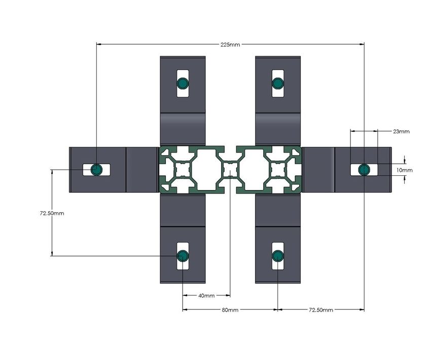
User Manual A

IMPORTANT SAFETY INSTRUCTIONS
This document contains instructions and warnings that must be followed when installing and using the Electric Vehicle
Supply Equipment (EVSE). Before installing or using the EVSE, read this entire document as well as WARNING and
CAUTION markings in this document.

Safety Instructions
The symbols used have the following meaning:

          DANGER – WILL RESULT IN DEATH OR SERIOUS INJURY

          WARNING- COULD RESULTS IN SERIOUS INJURY OR DEATH

          CAUTION- COULD RESULT IN MINOR OR MODERATE INJURY

          NOTICE- IMPORTANT INFORMATION

   • The charging station must be installed, adjusted, and repaired only by a licensed electrician.

   • Make sure that the materials used and the installation procedures follow local building codes and
     safety standards.

   • The information provided in this manual in no way exempts the user of responsibility to follow all
     applicable codes or safety standards.

   • This document provides instructions for the charging station and should not be used for any other
     product. Before installation or use of this product, review this manual carefully and consult with a
     licensed contractor, licensed electrician, or trained installation expert to make sure of compliance with
     local building codes and safety standards.

   •        WARNING FAILURE TO FOLLOW ELECTRIC CODE CAN RESULT IN SERIOUS INJURY OR DEATH: To
       reduce the risk of fire, connect only to a circuit provided with the minimum branch circuit overcurrent
       protection requirements in accordance with the National Electrical Code, ANSI/NFPA 70, and the
       Canadian Electrical Code, Part I, C22.1.
   Repair and Maintenance Clause
   • All EVOCHARGE products do not require routine maintenance however, periodic inspections should be conducted
     to ensure that all parts remain in good working order and no damage exists. Do not attempt to open,

EVOCHARGE Pedestal Installation Guide & User Manual                                                                 1
Part No. 701039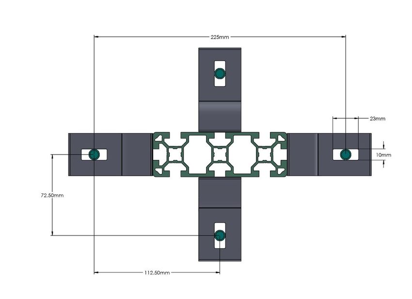
User Manual A

     disassemble, repair, tamper with, or modify any components of the products – the products are not user
     serviceable. Contact EVOCHARGE for any repairs.
   • Only licensed electricians can repair or maintain the charging station. It is forbidden for general users to repair or
     maintain it. Turn off input power before performing any repairs or maintenance to the charging station.

   FCC Declaration of Conformity
   • This charging station complies with part 15 of the FCC Rules. Changes or modifications the charging
     station not expressly approved by the manufacturer could void FCC compliance.
   • Operation is subject to the following two conditions: (1) This charging station may not cause harmful
     interference, and (2) this device must accept any interference received, including interference that may
     cause undesired operation.

   OVERALL WARNINGS & CAUTIONS
          WARNING- RISK OF ELECTRICAL SHOCK FAILURE TO FOLLOW THESE INSTRUCTIONS CAN
          RESULTS IN DEATH OR SERIOUS INJURY.
          Basic precautions should always be followed when using electrical products, including the
          following:
           •   Read all the instructions before using this product.
           •   This device should be supervised when used around children.
           •   Do not put fingers into the EV connector.
           •   Do not uses this product if the flexible power cord or EV cable is frayed, has broken
               insulation, or any other signs of damage.
           •   Do not use this product if the enclosure or the EV connector is broken, cracked, open, or
               shows any other indication of damage.
            WARNING- RISK OF ELECTRICAL SHOCK FAILURE TO FOLLOW THESE INSTRUCTIONS CAN
            RESULTS IN DEATH OR SERIOUS INJURY.
            Improper connection of the equipment grounding conductor can result in a risk of electric
            shock. Check with a qualified electrician or serviceman if you are in doubt as to whether the
            product is properly grounded.

            WARNING- RISK OF ELECTRICAL SHOCK FAILURE TO FOLLOW THESE INSTRUCTIONS CAN
            RESULTS IN DEATH OR SERIOUS INJURY.
             • Do not touch live electrical parts.
             • Incorrect connections may cause electric shock.
            WARNING: This equipment is intended only for charging vehicles that do not require
            ventilation during charging. Please refer to your vehicle’s owner’s manual to determine
            ventilation requirements.

EVOCHARGE Pedestal Installation Guide & User Manual                                                                      2
Part No. 701039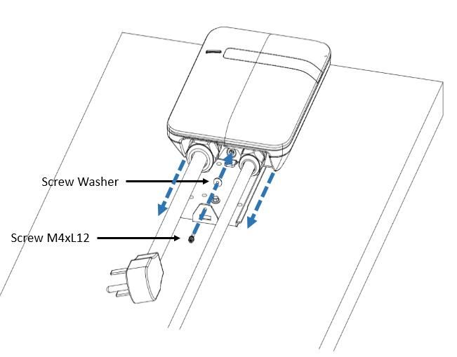
User Manual A

Product Features
    •   High-strength aluminum
    •   Suitable for single or dual mount of EVOCHARGE Charging Stations, EVOREEL’S or Retractor

                                                 Single Mount Example

                                                  Dual Mount Example

EVOCHARGE Pedestal Installation Guide & User Manual                                                3
Part No. 701039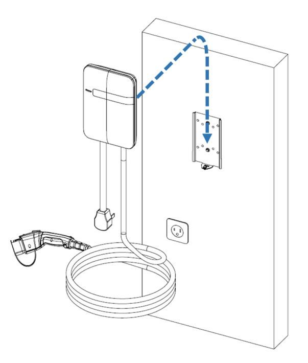
User Manual A

Product Specifications
EVOCHARGE® Pedestals
     Description                Specifications
     Pedestal – 4, 6 or 8 ft.   High-strength aluminum
     Color                      Gray
                                4 ft. 4 in.
     Maximum Height
                                6 ft. 4 in.
     (Nominal)
                                8 ft. 4 in.

EVOCHARGE Pedestal Installation Guide & User Manual                   4
Part No. 701039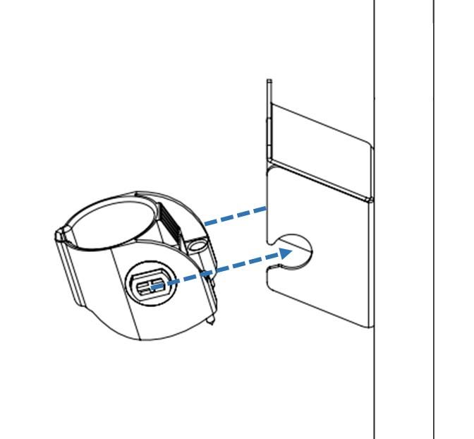
User Manual A

                                    SAVE THESE INSTRUCTIONS
Manual Contents
Contents

1   INTRODUCTION & UNPACKING .......................................................................................................................... 6

       Unpacking .............................................................................................................................................................................6

2   INSTALLATION ......................................................................................................................................................... 7

       Before Installation ................................................................................................................................................................7

       Tools & Parts Required for Installation .................................................................................................................................8

       Install the Charging Station & Pedestal .................................................................................................................................8

       Input Wiring Connection (Hardwire Connection) ................................................................................................................ 11

       Install Charging Station to Wall Bracket .............................................................................................................................. 13

       Install the Plug and Cable Holder ........................................................................................................................................ 14

EVOCHARGE Pedestal Installation Guide & User Manual                                                                                                                                       5
Part No. 701039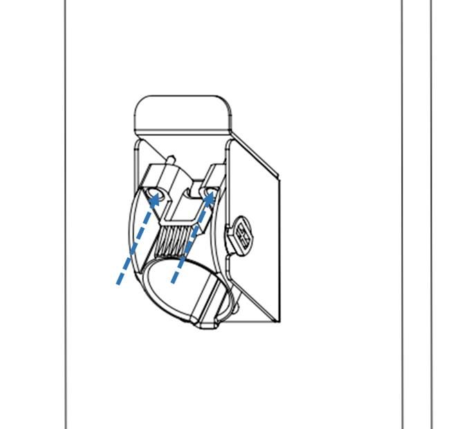
User Manual A

1 Introduction & Unpacking
This user manual applies to the pedestals for mounting EVOCHARGE charging stations and cable management systems.

       Unpacking
Unpackage all items and confirm the contents as noted below.

                                                 Figure 1-1 Box Contents

                                                 Table 1-1 Box Contents
     Pedestal Type                                    Part Description                            Qty
                        4 ft. Aluminum Pedestal                                                    1
                        Mounting Bracket Kit Includes:
                        -4 Mounting Brackets
 4 ft. Pedestal                                                                                     2
                        -4 Mounting Brackets Cover
                        -4 Concrete Anchors
                        End Cap                                                                     1
                        6 ft. Aluminum Pedestal                                                     1
                        Mounting Bracket Kit Includes:
                        -6 Mounting Brackets
 6’ ft. Pedestal                                                                                    3
                        -6 Mounting Brackets Cover
                        -6 Concrete Anchors
                        End Cap                                                                     1
                        8 ft. Aluminum Pedestal                                                     1
                        Mounting Bracket Kit Includes:
                        -6 Mounting Brackets
 8 ft. Pedestal                                                                                     3
                        -6 Mounting Brackets Cover
                        -6 Concrete Anchors
                        End Cap                                                                     1

EVOCHARGE Pedestal Installation Guide & User Manual                                                            6
Part No. 701039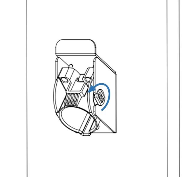
User Manual A

2 Installation
      Before Installation
2.1.1 Installation Planning & Service Wiring
          FAILURE TO FOLLOW THESE INSTRUCTIONS CAN RESULT IN DEATH OR SERIOUS INJURY.
           • Do not touch live electrical parts.
           • Incorrect connections may cause electric shock.
           • Disconnect the power supply to the charging station and verify no power is present before installing,
              adjusting, or repairing the charging station. Failure to do so may result in physical injury or damage to
              the power supply system and the charging station.

The charging station must be installed only by a licensed electrician in accordance with the provisions of the local
electrical industry construction and should comply with national electrical codes and standards.

Before installing the charging station, make sure you have read these instructions in this manual and fully understand its
contents.

Appropriate protection is required when connecting to a main panel/switchboard. The tools and parts used as outlined
in the section “Tools & parts required for installation”.

Prior to mounting, determine location of an acceptable mounting support.

Prior to mounting, locate an available electrical source that can support the following Input Requirements for the
Charging Station Per National Electric Code (NEC) requirements:
   • 32A Maximum Output Setting (Default Factory Setting): a DEDICATED CIRCUIT rated for 40A; 208-240 VAC, 50-60
       Hz, Single Phase must be used. Circuits rated greater than 40A may also be used.
   • Additionally, any Current Output less than 32A can be programmed using dipswitch, refer to Charging Station
       Installation Guide & User Manual.
   • A Double Pole Circuit Breaker of the circuit rating must be used. The Charging Unit has a built in GFCI protection;
       do not provide any additional GFCI protection upstream of the charging unit.

          WARNING: INCORRECT WIRING CAN RESULT IN DEATH OR SERIOUS INJURY: The service wiring in this
          section are specific to North America only. Before installing the Charging Station, identify the type of utility
          service connection available onsite. If you have unsure about the type of connection available at the service
          panel, contact your utility service provider.

EVOCHARGE Pedestal Installation Guide & User Manual                                                                       7
Part No. 701039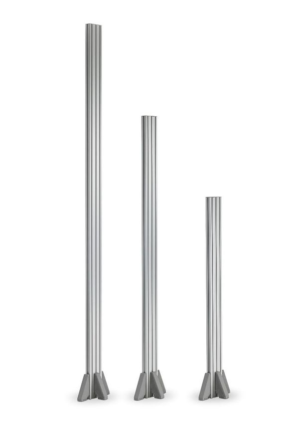
User Manual A

2.1.2 Grounding Instructions
The charging station must be implemented equipment grounding through a permanent wiring system or an equipment
grounding conductor. Use a wire with a dedicated grounding wire and a ring terminal and connected to the equipment
ground terminal block for grounding.

      Tools & Parts Required for Installation
                                       Table 2-1 Tools & Parts Required for Installation
                                Phillips #2 Screw driver or bit
                                Torx T20 Screwdriver or bit

                                8 AWG Ring terminal crimping tool
                                4mm Hex drive
                                5mm Hex drive

                                7/32" Hex drive
                                9/16" Socket or Wrench

      Install the Charging Station & Pedestal
         2.3.1 To begin the product assembly, install the supplied (4) Mounting Brackets to the base of the Pedestal
               Mount. Install the mounting brackets in the center location of each side (4 total) of the pedestal as show
               in Figure 2-1:

                                          Figure 2-1 Mounting Bracket Screw Hole Locations

        Ensure the (4) Mounting Brackets are positioned to be in flush contact with the ground mounting surface.

EVOCHARGE Pedestal Installation Guide & User Manual                                                                   8
Part No. 701039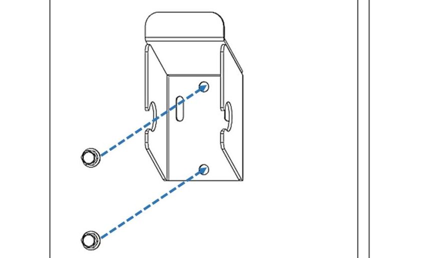
User Manual A

                                                      4-Foot Pedestal Mount

                                                 6 & 8-Foot Pedestal Mount

EVOCHARGE Pedestal Installation Guide & User Manual                           9
Part No. 701039
User Manual A
2.3.2 With the Pedestal Mounting Brackets installed, position the pedestal in the desired mounting
location and use the mounting bracket Anchor Stud/Bolt holes as a template to install the
appropriate Anchor Bolts/Studs for mounting the pedestal to the Ground. With the appropriate
Anchor Bolts/Studs installed to the mounting surface, install and fasten the Pedestal Mount to the
ground.
WARNING: FAILURE TO PROPERLY MOUNT THE PEDESTAL CAN RESULT IN DEATH OR SERIOUS INJURY.
Prior to mounting, determine a location with acceptable ground structural support to mount the Pedestal.
All charging station products and pedestal mounts must be anchored into a mounting structure that is
approved by local codes and requirements using mounting hardware that is appropriate for the surface on
which you are mounting. Please consult with a local building engineer and inspector to determine mounting
structure requirements. It is the responsibility of the Installer and/or Charging Station Owner to ensure and
confirm that the installation and anchoring of the Product are in full compliance with all Building Code
Requirements required of the location of install.
The Anchors included with the product are intended for mounting into appropriate concrete base/pad.
Anchor Installation Instructions:
1) Drill a hole in the base material using a carbide drill bit the same diameter as the nominal diameter of the
anchor to be installed (3/8”). Drill the hole to the specified minimum hole depth (1-7/8” minimum), and
blow the hole clean using compressed air.
2) Assemble the anchor with nut and washer so the top of the nut is flush with the top of the anchor. Drive the
anchor into the hole to at least the minimum hole depth.
3) Tighten the anchor nuts to the required installation torque (30 lbf-ft. for 3/8” bolt diameter).
2.3.4 Next, prepare to install all components to the Pedestal Mount using the supplied fastener components.
The insertion nuts install into the Pedestal Aluminum Extrusion channel and contain a spring-loaded
ball feature to hold them in place during assembly. To install the insertion nuts into the Aluminum
Extrusion channel, insert the insertion nuts into the extrusion channel at an angle as shown in Figure 2-
2, below:
Figure 2-2 Installing the insertion nuts into the aluminum extrusion channel
2.3.5 To install each item, install the insertion nuts into the extrusion channel at the approximate positions
each item will be installed.
EVOCHARGE Pedestal Installation Guide & User Manual 10
Part No. 701039User Manual A
2.3.6 Install the EVSE (charging station box) bracket to one side of the pedestal so that the middle of the
bracket is approximately 48 inches from the ground. Only two screws will be used to attach the
mounting bracket to the pedestal, the screws should pass (install) through the middle two vertical screw
holes of the mounting bracket as shown in Figure 2-3.
Figure 2-3 Mounting Bracket Screw Hole Locations
2.3.7 Next, install the Connector/Plug Holder below the charging station (EVSE) unit.
Input Wiring Connection (Hardwire Connection)
WARNING: IMPROPER WIRING CAN RESULT IN DEATH OR SERIOUS INJURY. FOLLOW LOCAL ELECTRIC CODE WHEN MAKING ANY
ELECTRICAL INSTALLATION.
2.4.1 Choose the appropriate conduit and fitting in accordance with all applicable state, local and national
electrical codes and standards. Please note the charging station knock-out size for the input wiring
connection is 1” NPT.
Figure 2-4 Conduit.
2.4.2 Using the appropriate tool, clamp the wire terminal to the copper wire. For non-insulated terminals, use
heat shrink tube to cover the non-insulated portion of the terminal.
EVOCHARGE Pedestal Installation Guide & User Manual 11
Part No. 701039User Manual A
Figure 2-5 Copper terminal, heat shrink tube and copper wire.
2.4.3 Connecting the electrical wiring to the charging station.
2.4.4 Place the Charging Station on a flat surface, front cover down with protection under the cover to avoid
scratching damage to the cover.
2.4.5 Remove the Charging Station front cover by loosening the (5) Torx screws at the rear of the charging
station.
Figure 2-6 Five Torx screw locations to remove the Charging Station Cover
2.4.6 With the (5) Torx screws loosened, hold the front cover in place and flip the charging station over on the
flat surface so that the front cover is on top. Once this is completed, lift the charging station front cover
and place to the right side of the charging station unit.
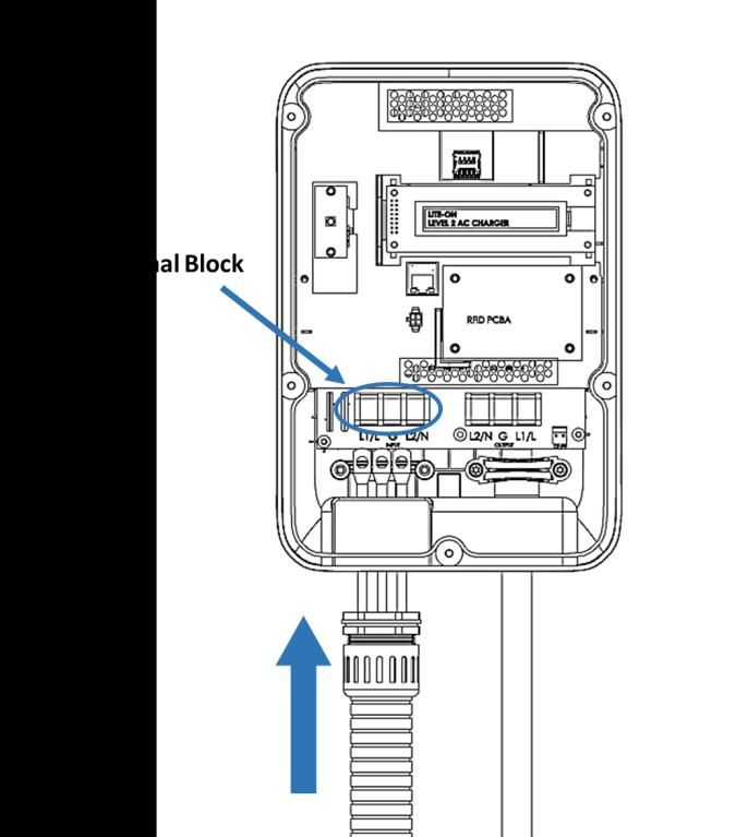
2.4.7 With the front cover placed to the side, insert the wire end passing through the conduit and insert them
into the input wiring hole. (Use Red wire for L1, Black wire for L2, Green-yellow wire for G). Attach the
copper wire on the corresponding terminal block. Use the following wire and torque force when
connecting to input terminal block, using conductor type other than RHH, RHW and RHW-2 with outer
covering.
Terminal Conductor Screw Rating Torque
L1, L2, G 8 AWG M4 90C, copper wire 16 kgf.cm 13.88 lb-in
EVOCHARGE Pedestal Installation Guide & User Manual 12
Part No. 701039User Manual A
Figure 2-7 Input wiring
WARNING INCORRECT CIRCUIT AMPERAGE RATING CAN RESULT IN DEATH OR SERIOUS
INJURY: To reduce the risk of fire, connect only to a circuit provided with the appropriate
amperes minimum branch circuit overcurrent protection in accordance with the National
Electrical Code, ANSI/NFPA 70, and the Canadian Electrical Code, Part I, C22.1.
Current Setting Circuit Rating Requirement
32A 40A or greater
2.4.8 Once the input wiring and conduit are connected, reassemble the charging station.
2.4.9 4-1. Reinstall the charging station font cover using the following torque force to secure the (5) Torx
screws:
Screw Torque
M4 16 kgf.cm 13.88 lb-in
Install Charging Station to Wall Bracket
2.5.1 As shown in Figures 2-8 & 2-9, mount the charging station onto the mounting bracket and secure the
lock screw.
2.5.2 Tighten the installed M4 screw and screw washer to fix charging station on mounting bracket.
2.5.3 Use following torque force:
Screw Torque
M4 16 kgf.cm 13.88 lb-in
EVOCHARGE Pedestal Installation Guide & User Manual 13
Part No. 701039User Manual A
Figure 2-8 Charging station and mounting bracket Figure 2-9 Screw locking position
Install the Plug and Cable Holder
2.6.1 Separate the holder from hook.
Figure 2-10 Separate the holder
2.6.2 Install the Holder bracket (hook) below the charging station using the supplied fasteners
EVOCHARGE Pedestal Installation Guide & User Manual 14
Part No. 701039User Manual A
Figure 2-11 Secure the hook
2.6.3 Position the plastic holder insert face up and install into the holder bracket.
Figure 2-12 Secure the holder
2.6.4 Next, rotate the holder insert down.
EVOCHARGE Pedestal Installation Guide & User Manual 15
Part No. 701039User Manual A
Figure 2-13 Rotate the holder
2.6.5 With the holder insert in the down position, tighten the (2) lock/set Philips screws located at the top of
the plastic holder component until snug (do not overtighten). The screws ensure that the plastic holder
component remains secured to the holder bracket.
Figure 2-24 Lock screws
2.6.6 Insert EV charging connector into the holder.
EVOCHARGE Pedestal Installation Guide & User Manual 16
Part No. 701039User Manual A
Figure 2-15 Insert EV Charging Connector into Holder
For Additional Products and Accessories visit www.phillpsandtemro.com or contact us at 1-800-328-6108.
EVOCHARGE Pedestal Installation Guide & User Manual 17
Part No. 701039You can also read