GRIZZL E SMART EV Charger
←
→
Page content transcription
If your browser does not render page correctly, please read the page content below
™
GRIZZL E
 SMART
EV Charger
      User Manual

   & Installation Guide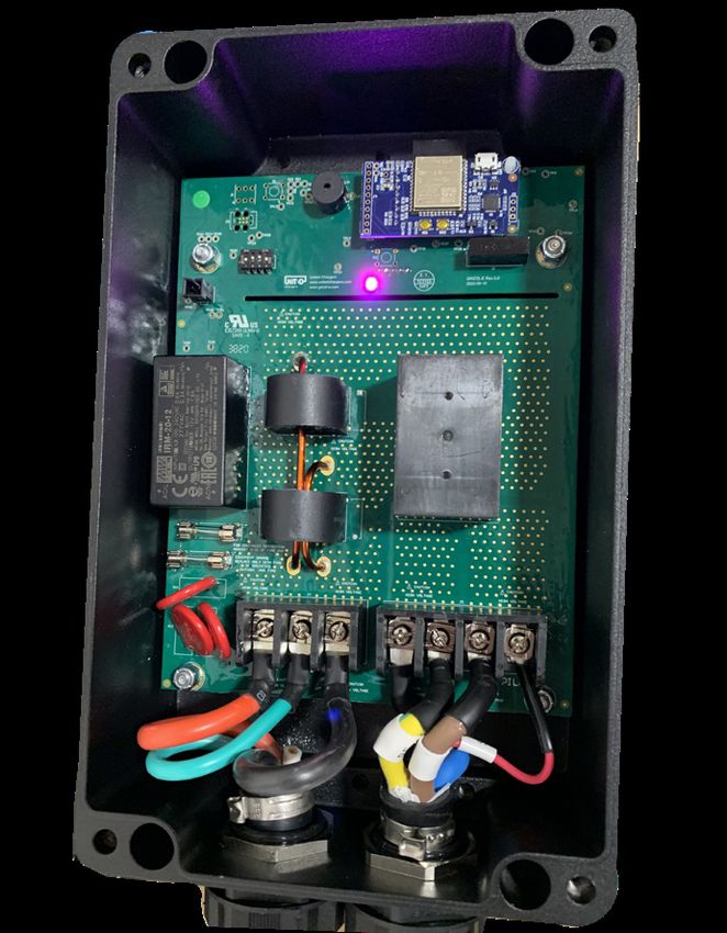
Grizzl-E Smart Manual v. 9.0

Model Numbers:

GRS-6-24-P

GRS-14-24-P

                               2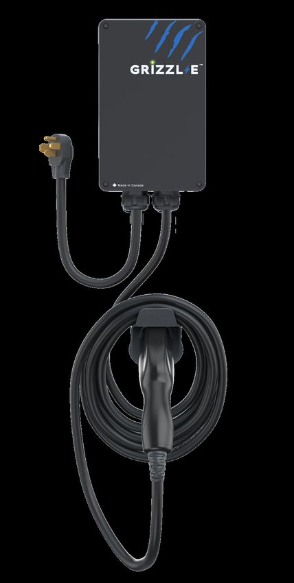
Grizzl-E Smart Home EV Charging Station
The Grizzl-E Smart is the Wi-Fi connected smart EV Charger built from the proven Grizzl-E
design. Grizzl-E Smart has Wi-Fi connectivity and can work with any OCPP 1.6 application. It is
a simple, powerful, heavy-duty, and portable electric vehicle charging station made in Canada
and built to withstand the harshest conditions.

The Grizzl-E Smart comes exclusively with a 24ft Premium cable. Internal design and
components of the charger have been selected to provide maximum operational life of the
device and be able to withstand the elements.

Grizzl-E Smart provides up to 10 KW of power to your vehicle. Maximum current output can
be set through DIP Switches to provide 16 Amps, 24 Amps, 32Amps or 40 Amps adjustable
maximum current.

IMPORTANT SAFETY INSTRUCTIONS
This document contains instructions and warnings that must be followed when installing and
using the Grizzl-E Smart Electric Vehicle Supply Equipment (EVSE). Before installing or using
the EVSE, read this document including any WARNING and CAUTION symbols.

The Symbols Used Have the Following Meanings

        Warning: risk of personal injury               Warning: risk of fire

         Warning: risk of electric shock               Caution: risk of damage to equipment

•   This document provides instructions for the charging station and should not be used for
    any other product. Before installation or use of this product, review this manual carefully
    and consult with a licensed contractor, licensed electrician, or trained installation expert to
    ensure compliance with local building codes and safety standards.
•   Consult a licensed electrician to ensure that you can safely install and use this product.
•   Ensure that the materials used, and the installation procedures, follow local building codes
    and safety standards.
•   The information provided in this manual in no way exempts the user of responsibility to
    follow all applicable codes or safety standards.

                                                                                             3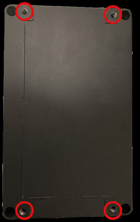
Basic precautions should always be followed when using electrical products,
including the following:

•   Read all the instructions before using this product.
•   Children should not use this device.
•   Do not put fingers into the EV connector.
•   Do not touch live electrical parts.
•   Do not use this product if the flexible power cord or EV cable is ragged, has broken
    insulation, or any other signs of damage.
•   Do not use this product if the enclosure or the EV connector is broken, cracked, open,
    or shows any other indication of damage.
•   Improper connection of the equipment grounding conductor can result in a risk of electric
    shock. Check with a licensed electrician if you are in doubt as to whether the product is
    properly connected and grounded.

Repair and Maintenance Clause

•   All United Chargers products do not require routine maintenance however, periodic
    inspections should be conducted to ensure that all parts remain in good working order
    and no damage exists.
•   Do not attempt to open, disassemble, repair, tamper with, or modify any components of
    the products. Contact United Chargers for any repairs.

                       WARNING: This equipment is intended only for charging vehicles
                       that do not require ventilation during charging. Please refer to your
                       vehicle’s owner’s manual to determine ventilation requirements.

                                                                                           4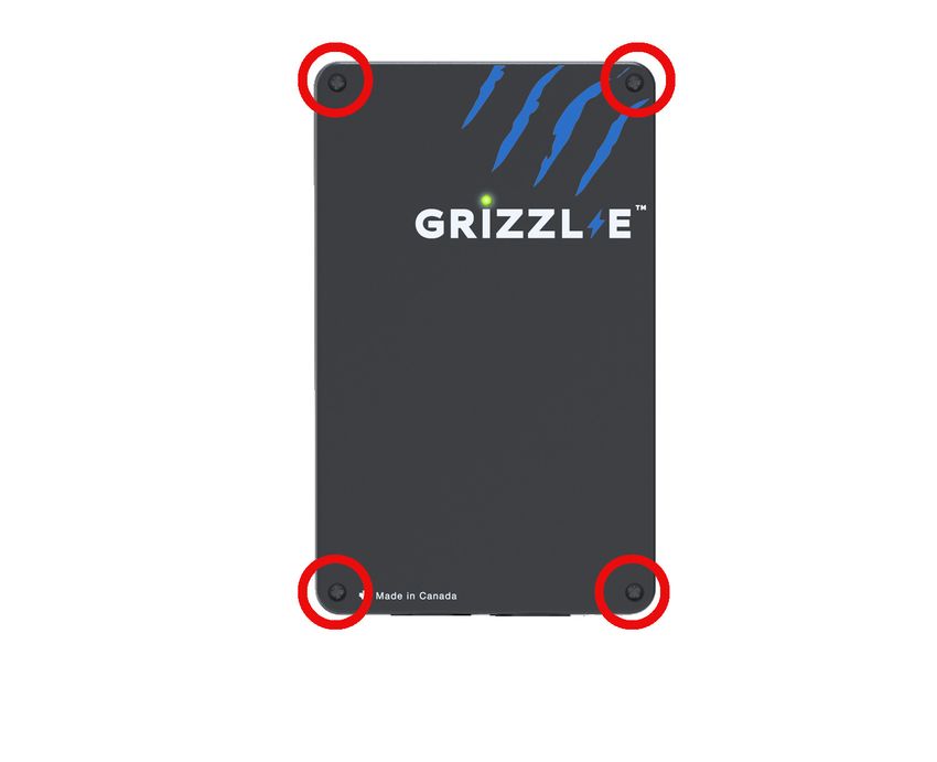
Product Features
GRIZZL-E™ Smart Electric Vehicle Charging Station (EVSE)

•   J1772 AC Level 2 (208-240 VAC), 40A Continuous Rated (9.6 kW)
•   Adjustable Maximum Current Output (40A, 32A, 24A, 16A) to Support Multiple Circuit
    Ratings (50A, 40A, 30A, 20A)
•   Extreme Duty, Rigid & Compact Design:
•   Robust and heavy-duty aluminum cast case; airtight enclosure for indoor or outdoor use
•   Wi-Fi Connectivity. Smart Charging Features.
•   Compatible with all OCPP 1.6 applications.
•   EasyEvPlug™ Holster or Tesla EasyEVPlug™ Holster with cable Management System.
•   Plug-in Configuration for easy portability.
•   Wall Mount with security features (including single stud mount), Pedestal, Bollard/Pole
    (Single & Dual Port) available from United Chargers.
•   UL Certified

Adjustable Maximum Current Output to Support Multiple Circuit Ratings

The GRIZZL-E™ Electric Vehicle Charging Station features the ability to adjust the maximum
charging station current output to allow the use of a 50A, 40A, 30A, or 20A Dedicated Circuit
as follows:

50A Circuit Rating:		         To support 40A (9.6kW) Maximum Charging Station Output
40A Circuit Rating:		         To support 32A (7.68kW) Maximum Charging Station Output
30A Circuit Rating:		         To support 24A (5.76kW) Maximum Charging Station Output
20A Circuit Rating:		         To support 16A (3.84kW) Maximum Charging Station Output

The Default Factory Setting is 40A (9.6kW). To change the maximum current output, refer to
Chapter 4.1 Adjust Maximum Current Output on page 12.. If you are unsure of the circuit
ratings in your home consult a licensed electrician.

Self-Monitoring and Recovery | Power Outage Recovery

When a charging session is interrupted due to a temporary error condition, the charging
station will automatically restart charging when the cause of the temporary error condition
returns to normal. Refer to Chapter 11.3 Self-Monitoring and Recovery (Auto Restart) on page
27 for more information.

Security and Tamper Feature
In addition to the included security pin that secures the charging station to the wall mount
bracket, a coupler lock and key with a length of 90mm and diameter of 7mm can also be used
to lock and secure the Grizzl-E Charging Station to the wall mount.

                                                                                          5
Product Specifications
United Chargers GRIZZL-E™ Electric Vehicle Charging Station (EVSE)

    Description          Specifications

   Model Numbers
                       GRS-6-24-P
                       GRS-14-24-P

     EVSE Level         SAE J1772; AC Level 2

    Max Output         40A; 9.6 kW Maximum Output – For use with 50A Circuit Rating
      Rating

     Alternate         32A; 7.68 kW Maximum Output – For use with 40A Circuit Rating
 Adjustable Output     24A; 5.76 kW Maximum Output – For use with 30A Circuit Rating
      Ratings          16A; 3.84 kW Maximum Output – For use with 20A Circuit Rating

    Charge Cable        24 ft.
      Length

  Electrical Circuit   Circuit Requirement: Dedicated Single Phase 208-240VAC, 50/60 Hz.;
    / Input Power      Branch Breaker: Double pole;
   Requirements        Circuit Conductors: Line 1, Line 2, Earth / Ground

    Input Power        Standard: Plug-in, NEMA 6-50 or NEMA 14-50 Plug.
     Connection        Plug is removable for Hardwire Connection.

  Charging Station
                       Standard: Black
       Color

 Installation Rating   NEMA 4, Indoor/Outdoor Rated

                       Temperature: -22⁰F to 122⁰F (-30⁰C to 50⁰C); Humidity: 95% RH
Operational Ratings
                       non-condensing

      Mounting         Wall or Pedestal Installation

 Overall Dimensions    EVSE: 10.25 x 6.25 x 3.75 inches (26.0 x 16.0 x 9.3 cm)

Display & Indicators   LED Charge Status Indicators (Power/Ready, Charging, Fault)

 Cable Management      EasyEvPlug™ with cable management

    Standards &
                       UL Certified                                                    6
    Compliance
7
INSTRUCTIONS Manual

Table of Contents
1. Introduction & Unpacking ................................................................................ 9
2. Installation Planning and Service Wiring: ..................................................... 10
          2.1 Electrical Source Requirements ................................................................ 10
          2.2 Grounding Instructions .............................................................................. 10
3. Calibrating the GRIZZL-E Unit (Optional)....................................................... 11
4. Adjustable Maximum Current Output........................................................... 12
          4.1 Adjust Maximum Current Output.............................................................. 12
5. Installation........................................................................................................ 15
          5.1 Tools & Parts Required for Installation .................................................... 15
          5.2 Install the Charging Station ....................................................................... 16
6. Input Wiring Connection (Optional Hardwire Connection)......................... 19
7. EasyEvPlug Holster and Cable Management System.................................... 20
8. Set Up Smart Functionality.............................................................................. 21
          8.1 Create account on United Chargers Portal .............................................. 21
          8.2 Connect the Grizzl-E to your Wi-Fi, and to OCPP Server ........................ 21
          8.3 Connect to United Chargers Portal .......................................................... 21
          8.4 Connect to Third Party OCPP Network..................................................... 21
9. Re-Set Wi-Fi Board ............................................................................................ 22
          9.1 Change OCPP Network .............................................................................. 23
10. Charging Status Indicators and Buzzers ..................................................... 24
          10.1 Charging Status Indicators ...................................................................... 24
          10.2 Fault Indicators ......................................................................................... 25
11. Operation ........................................................................................................ 26
          11.1 Connect and Charge ................................................................................. 26
          11.2 Stop Charging ............................................................................................ 26
          11.3 Self-Monitoring and Recovery (Auto Restart) ....................................... 26
12. General Product Care and Use Information ............................................... 27

13. Warranty......................................................................................................... 28

                                                                                                                        8
1. Introduction & Unpacking
This user manual applies to the GRIZZL-E ™ EVSE for Plug-in Hybrid Electric Vehicles (PHEVs)
and Electric Vehicles (EVs).
Charging Station with input and Mounting Bracket (x1)
output cable (x1)
Security Pin (x1) Robertson Head Socket Cap Screw
Screws (x2)
Phillips-head Anchor (x4)
Screws (x4)
Holster (x1)
92. Installation Planning and Service Wiring:
WARNING: Disconnect the power supply to the charging station
before installing, adjusting, or repairing the charging. Failure to do so
may result in physical injury or damage to the power supply system
and the charging station.
CAUTION: To reduce the risk of fire, connect only to a circuit
provided with the minimum branch circuit overcurrent protection
requirements in accordance with the National Electrical Code ANSI/
NFPA 7- and the Canadian Electrical Safety Code, Part 1, C22.1. If
you are unsure if your circuit meets these requirements consult a
licensed electrician.
2.1 Electrical Source Requirements
• Prior to mounting, locate an available electrical source that can support the following
Input Requirements for the Charging Station Per local Electrical Safety Code requirements:
» 40A Maximum Output Setting (Default Factory Setting): a DEDICATED CIRCUIT rated
for 50A; 208-240 VAC, 50-60 Hz, Single Phase must be used.
» 32A Maximum Output Setting (Optional Setting): a DEDICATED CIRCUIT rated for 40A;
208-240 VAC, 50-60 Hz, Single Phase must be used.
» 24A Maximum Output Setting (Optional Setting): a DEDICATED CIRCUIT rated for 30A;
208-240 VAC, 50-60 Hz, Single Phase must be used.
» 16A Maximum Output Setting (Optional Setting): a DEDICATED CIRCUIT rated for 20A;
208-240 VAC, 50-60 Hz, Single Phase must be used.
• A Double Pole Circuit Breaker of the circuit rating must be used.
• The Charging Unit has a built in GFCI protection; do not provide any additional GFCI
protection upstream of the charging unit.
• The Charging Stations can connect a Standard NEMA 14-50 Receptacle, or the unit can be
hardwired
2.2 Grounding Instructions
The charging station must be implemented equipment grounding through a permanent
wiring system or an equipment grounding conductor. Use a cable with a dedicated grounding
conductor connected to the equipment ground terminal block.
103. Calibrating the GRIZZL-E Unit (Optional)
WARNING: Electrical Power MUST remain OFF and DISCONNECTED
before setting or changing the DIP switch. Incorrect connection may
cause electric shock.
Note:
Calibration should be done before adjusting the charging station’s maximum current output
settings and connecting the unit to Wi-Fi.
Calibration Steps:
1. Unplug the charger and remove the front cover by removing the 4 screws at each corner
of the charging station. For more information on how to remove the front cover refer to
Chapter 4.1 Adjust Maximum Current Output on page 12.
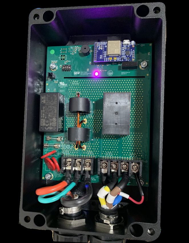
2. With the front cover placed to the side, locate the DIP switch on the charging station circuit
board. The DIP switch is a 4-position switch on the main circuit board, located directly to
the left of the LED. Using a non-conductive object, calibrate the Grizzl-E unit by adjusting
the DIP switch settings as follows:
UP DOWN UP UP
3. Plug in the charger until the LED turns solid red. The solid red LED indicates that
the calibration is finished.
4. Unplug the charger. Reset the DIP switches to the original position.
5. Plug in the charger. Ensure that LED indicator light shows Blue and Purple
alternating.
6. Replace the enclosure lid by tightening the 4 screws at each corner or follow the
steps from the user manual to set the maximum current output. Refer to Chapter
4.1 Adjust Maximum Current Output on page 12.
114. Adjustable Maximum Current Output
The GRIZZL-E Smart charging station features the ability to adjust the maximum Charging
Station current output to support 50A, 40A, 30A, or 20A Dedicated Circuit ratings as follows:
Circuit Rating Maximum Charging Station Output
50A 40A (9.6 kW)
40A 32A (7.68 kW)
30A 24A (5.76 kW)
20A 16A (3.84 kW)
• The Charging Station Default Factory Maximum Current Output Setting is 40A (9.6 kW) for
use with a 50A Circuit Rating.
• The Circuit must be a DEDICATED CIRCUIT 208-240 VAC, 50-60 Hz, Single Phase.
• Requirements govern that only 80% of the circuit rated load may be utilized, hence the
higher Circuit Ratings Requirement relative to maximum Charging Station output.
4.1 Adjust Maximum Current Output
To adjust the Maximum Current Output Setting:
1. Place the Charging Station on a flat surface with the front cover facing up.
2. Remove the front cover by removing the 4 screws at each corner of the charging station.
Use a M4 Allen Key to remove the screws.
12CAUTION: The LED pipe is attached to the front cover. When the
front cover is removed, place it on a flat surface facing down to avoid
damage to the LED pipe.
3. With the front cover placed to the side, locate the DIP switch on the charging station circuit
board. The DIP switch is a 4-position switch on the main circuit board, located directly to
the left of the LED.
UP UP UP DOWN
WARNING: Do not touch live electrical parts. Disconnect the power
supply to the charging station and verify no power is present before
adjusting the DIP Switches. A non-conductive object MUST be used to
adjust the DIP switch settings. Failure to do so may result in physical
injury or damage to the power supply system and the charging station.
134. Using a non-conductive object adjust the Maximum Current Output to either 32A, 24A or
16A, using the following combination of DIP switch settings:
Switch 1 Switch 2 Switch 3 Switch 4
40A Maximum Current Output UP UP UP DOWN
(Factory Default Setting)
32A Maximum Current Output UP DOWN UP DOWN
24A Maximum Current Output UP UP DOWN DOWN
16A Maximum Current Output UP DOWN DOWN DOWN
5. Once the DIP Switch Setting is adjusted, reassemble the charging station. Reinstall the top
cover to the charging station using the following torque force to secure the 4 socket cap
screws:
Screw Torque
M6 16 kgf-cm 13.88 lb-in
145. Installation
5.1 Tools & Parts Required for Installation
Prior to mounting, determine the location of an acceptable mounting support. All charging
station products must be anchored into a mounting support such as a 2” x 4” stud or a solid
concrete wall. DO NOT mount this unit directly to a stucco/drywall/wall board.
Tool Size Source of Supply Remark
Mounting Bracket 255 x148 x 36 mm Included with Product For mounting the charging
station to the wall/structure
For securing the charging
Socket cap screw 5/16” Included with Product
station to the Mounting
(x4)
Bracket
Robertson-Head Screw #14 Included with Product For installing the Mounting
(x2) Bracket to the wall/structure
Holster/Tesla Holster™ 58 x 58 x 70 mm Included with Product To store the EV charging Plug
and Cable
For installing the
Phillips-Head Screw #8
Included with Product EasyEvPlug™ to the wall/
(x4)
structure
Anchors #8 Included with Product For installing the EasyEvPlug™
(x4) to the wall/structure
Philips Screwdriver PH3 Commercially Available For Holder Installation and
Optional Hardwire Install
Allen key Commercially Available For Charging Station Cover
M4
Screws
Commercially Available For installing the enclosure
Allen key 3/16”
plate to the back of the
station body.
155.2 Install the Charging Station
1. Separate the front and back piece of the mounting bracket by pushing down on the
notch.
Back Piece
Front Piece
2. Attach the front piece of the mounting bracket to the back of the charging station
using the Socket-cap screws. Ensure the top of the mounting bracket is matched with
the top of the charging station.
TOP
163. Secure the back piece of the mounting bracket to the wall or other suitable structure
using the Robertson-head screws.
The back piece of the mounting bracket has 3 holes to support attachment to various
surfaces. Use the top two holes to attach the mounting bracket to a wall stud.
Mounting Screw Recommendations:
• For finished walls supported by wood studs, use #14 or M6 tapping screws. (Included).
• For masonry walls, use M6 mechanical screws. (Commercially available)
• Use following torque force:
Screw Torque
M6 50 kgf-cm 43.4 lb-in
1/4” 50 kgf-cm 43.4 lb-in
Mount the unit between 24 inches (0.6 m) and 48 inches (1.2 m) from the ground. The NEMA
outlet should be located no less than 20~26” from the ground or as defined by applicable,
local electrical safety codes and standards.
174. Mount the charger on the wall by securing the front piece of the mounting bracket to the
back piece of the mounting bracket.
5. Secure the charger in place by inserting either the security pin or the outdoor security lock
into the mounting bracket.
6. Plug in the power cord to the NEMA 14-50 Wall Outlet/Receptacle.
186. Input Wiring Connection (Optional Hardwire Connection)
1. Choose the appropriate conduit in accordance with all applicable, local, and electrical
safety codes and standards.
2. Using the appropriate tool, clamp the wire terminal to the copper wire. For non-insulated
terminals, use heat shrink tube to cover the non-insulated portion of the terminal.
3. Remove the front cover by removing the 4 screws at each corner of the charging station.
For more information on how to remove the front cover refer to Chapter 4.1 Adjust
Maximum Current Output on page 12.
4. With the front cover placed to the side, use Philips screwdriver to release terminal screws
of the or 14-50 Plug cable. Loosen the Strain Relief Fitting for the or 14-50 Plug and
Remove the Plug. Remove the Strain Relief connector.
5. Insert the wire end passing through the conduit and insert them into the input wiring hole.
(Use Red wire for L1, Black wire for L2, Green wire for G). Attach the copper wire on the
corresponding terminal block. Use the following wire and torque force when connecting to
input terminal block.
19
197. EasyEvPlug Holster and Cable Management System
The EasyEVPlug™ Holster or Tesla EasyEVPlug™ Holster is the new innovative method to pro-
tect your plug and manage your cord. It has the following features:
• No need to aim – flawless plug even in the dark.
• Your EV holster will always be in a convenient location.
• Saves space – special angle for less wall clearance.
• Integrated cable management – holds up to 25 feet of cable.
The EasyEvPlug holster can be installed at any location near the charging station.
1. Hold back of holster against the mounting
surface. Fasten Phillips head screws through
(x4)
back holes. Use anchors if attaching directly to
drywall.
2. Insert charging connector into holster.
3. Wrap cable on top of EasyEvPlug.
208. Set Up Smart Functionality
Grizzl-E Smart can connect to any OCPP 1.6 compatible
software.
8.1 Connect the Grizzl-E to your Wi-Fi
Note: Grizzl-E Smart is only compatible with 2.4 Ghz Wi-Fi. The Wi-Fi network must be at least
4 bars for smart features. If your computer or cell phone has less than 4 bars of Wi-Fi signal
you must install a Wi-Fi repeater to increase the signal strength (5 bars full signal strength is
preferred). If the signal strength is 3 bars or less, smart functionality will be unavailable.
1. Plug in the Charger.
2. Open the Wi-Fi settings on your smart phone or desktop.
3. Select the network UC_Smart_[ChargerSerial#].
4. Open the browser on your device.
5. Enter the IP address 192.168.4.1 into the browser search bar.
6. A webpage will load. Select the Enter Router Credentials button.
7. Enter the SSID Password for your Wi-Fi network. Enter the Portal URL for the OCCP server.
Follow the instructions provided by the OCPP Application provider.
8. Verify that you are connected. If connection is successful the buzzer will sound
continuously for 4 seconds and indicator light will alternate between Blue and Light Blue.
9. Disconnect your smartphone from UC_Smart_#### and re-connect to your local network.
10. Close the browser page.
218.2 Connect to United Chargers OCPP Network
Create an account on acharger.ca
1. Go to the website acharger.ca.
2. Select the Login button.
3. Select Sign Up button.
4. Enter your Name, Email, Username, and Password.
5. Select the Register button.
Add Device to United Chargers Portal
1. Login to your account at acharger.ca.
2. Go to the Charging Stations tab.
3. Select the Add button from the top menu.
4. Enter the Charger Serial Number (found on the label) in the Serial Number field.
5. Select the Create button. The created charging stations will show in the Charging Station
tab.
8.3 Connect to Third Party OCPP Network
1. Follow the directions on the third-party Network to configure your charging station with
the OCPP central system URL.
2. Wait for connection. If connection is successful the buzzer will sound continuously for 4
seconds. If the connection is unsuccessful consult the portal provider.
229. Re-Set Wi-Fi Board If the Grizzl-E Smart Charger has lost connection and is unable to re-establish the connection try resetting the board using the following procedure: 1. Unplug the Charging Station. Place the Charging Station on a flat surface with the front cover facing up. 2. Remove the front cover by removing the 4 screws at each corner of the charging station. For more information on how to remove the front cover refer to Chapter 4.1 Adjust Maximum Current Output on page 12 3. With the front cover placed to the side, locate the DIP switch on the charging station circuit board. The DIP switch is a 4-position switch on the main circuit board, located directly to the left of the LED. 4. Using a non-conductive object adjust the Left Switch to the down position. This applies for all amperage settings. 5. Plug the Charger back in. Wait until the LED flashes Blue/Purple alternating with 1 second frequency. 6. Unplug the Charger again. 7. Set the DIP switches back to the original position. 8. Plug the charger in. If the re-set is successful the buzzer will sound continuously for 4 seconds. Charger will display Blue/Purple alternating indicator light. 9. Replace the enclosure lid by tightening the 4 screws at each corner. 10. Follow the instructions from Chapter 8.2 Connect the Grizzl-E to your Wi-Fi, and to OCPP Server on page 21 to reconnect to your Wi-Fi network and OCPP Network. 23
9.1 Change OCPP Network

To Change OCPP Network to another provider:
1. Follow the instructions in Chapter 9. Re-Set Wi-Fi Board on page 23 to reset the Wi-Fi
   board.
2. Follow the directions on Chapter 8. Set Up Smart Functionality on page 21 and the third-
   party Network to configure your charging station with the OCPP central system URL.
3. Wait for connection. If connection is successful the buzzer will sound continuously for 4
   seconds. If the connection is unsuccessful consult the portal provider.

                                                                                            24
10. Charging Status Indicators and Buzzers
10.1 Charging Status Indicators
The following Status Indictors will be used in both Connected Modulated and Offline Solid
modes:
LED Indicator Buzzer Description Definition
No buzzer Not illuminated Power Off
No buzzer White Initialization
No buzzer Blue Alternating Ready
No buzzer Blue Flashing Vehicle detected
No buzzer Green Flashing Charging in progress
Charging complete or no
No buzzer Green Steady
current consumed by the car
Buzzer sounds Red Steady Unrecoverable Fault
continuously
Buzzer beeps for Red Flashing Recoverable Fault
5 times and then
stays off
No Buzzer Purple Alternating* Device is not connected to a
network
No Buzzer Light Blue Alternating** Device is connected to a
network
*LED will alternate between Blue and Purple when the charger is ready and disconnected
from the network
** LED will alternate between Blue and Light Blue when charger is ready and connected to
the network
2510.2 Fault Indicators
If the “Red Steady” or “Red Flashing” Fault Indicator remains use the following procedure:
1. Unplug the charging connector from your EV.
2. Turn off the power to the Charging Station by switching the upstream circuit breaker to
the “OFF” position
3. With the circuit breaker in the “OFF” position, wait 1-2 minutes and then switch the
upstream circuit breaker back to the “ON” position
4. Confirm the Fault light is no longer present. If the Fault light remains, please contact
United Chargers technical support.
2611. Operation
11.1 Connect and Charge
Insert the charging Connector into the EV and ensure the connector is fully seated/locked in
place. Once complete, the charging session will begin.
Charging will start in both Connected Mode (Light Blue indicator LED) and Standard Mode
(Purple indicator LED).
Figure 3-1. Connect the charging plug to the EV
11.2 Stop Charging
1. Unplug the charging station by pressing the connector button and removing the Charger
Connector from the EV (once the connector button is depressed, the charging session
terminates immediately).
2. Return the connector to the holster.
11.3 Self-Monitoring and Recovery (Auto Restart)
When a charging session is interrupted due to a temporary error condition, it will
automatically restart charging when the cause of the temporary error condition returns to
normal. The status indicator lights remain flashing RED until the error condition
is resolved.
• Temporary error conditions include: Over Current, Under Voltage, Missing Diode, Ground
Fault, and Over Temperature.
• For Over Current (OC) conditions: The charging session will be stopped while OC occurs.
After recovery from OC for 30 seconds, the charging station will automatically restart
charging for four times.
• When charging session stopped due to the Ground Fault (GFCI) trip, the charging station
will try to restart after 15 minutes for 4 times. After 4 times, the charging station buzzer
will stay on continuously, and status indicator will stay RED. The user should plug-out and
plug-in the power cable of the charging station.
2712. General Product Care and Use Information
The exterior of the charging station is designed to be waterproof and dust proof (NEMA 4
Outdoor Rated). However, periodic cleaning may be required, depending on local conditions.
To ensure proper maintenance of the charging station, follow these guidelines:
• To avoid damaging the finish of the products, only use an automotive grade soft cleaning
cloth with soap and water to remove accumulated dirt and dust. Do not use cleaning
solvents to clean any of the product components.
• Despite the water resistance of the enclosure, submerging the unit in water is not
recommended.
• Ensure the charging connector is put back in the holster after charging to avoid damage.
• Ensure the power cable is stored on the charging station after use to avoid damage.
• If the power cable or the charging connector is damaged, turn off the charging station
supply circuit breaker, do not use the charging station, and Contact United Chargers
Customer Support for replacement parts.
• When moving or lifting the unit, always grasp and carry by the charging station body.
Never attempt to lift, move, or carry the unit by any of the electrical cables. Improper
handling may cause damage to the unit.
2813. Warranty
GRIZZL-E ™ Smart EV Residential Charging Stations 3 Years Replacement Warranty.
Grizzl-E Smart comes with the option of a 3-year or 5-year manufacturer’s warranty.
This warranty is extended by United Chargers to original purchasers of GRIZZL-E ™ EV
Charging Stations. United Chargers warrants that this product is free from defects in materials
years and free from defects in workmanship for the period specified in the warranty from the
date of purchase. No agent, employee, or representative of United Chargers has any authority
to affirm, represent or warrant anything concerning GRIZZL-E ™ EV Charging Stations, except
for the affirmation and representation which is specifically included within this warranty.
This warranty will not apply if the product has been misused, abused, or altered. Warranty
for the cable does not include normal tear and wear. Plugs that have been exposed to snow
or water for a prolonged period of time are not covered by this warranty. The warranty will
apply only if the product is defective. United Chargers assumes no liability for any dismantling,
removal, installation, re-installation, or labor costs or any consequential damages associated
with this warranty. United Chargers is not responsible or liable for any costs associated with
faulty installations.
United Chargers shall make the final decision, in fairness to all concerned, as to the legitimacy
of any such claim on this warranty. Upon discovery of any defective GRIZZL-E ™, please
contact our Customer Service Department for further instructions as to how to repair or
replace the defective unit or log into your account at www.grizzl-e.com and submit support
ticket.
United Chargers Inc Phone: +1-833-840-4970
90 Gough Road, Unit 2
E-mail: info@unitedchargers.com
Markham, Ontario L3R 5V5 Canada
Website: www.grizzl-e.com
The most up to date and valid information is available at the online version of
brochure, located here:
https://grizzl-e.com/manuals/
29You can also read