Safe Use Instructions: Emerson FB1100 Flow Computer
←
→
Page content transcription
If your browser does not render page correctly, please read the page content below
Safe Use Instructions – Emerson FB1100
                                                                Part D301768X012
                                                                        June 2021

Safe Use Instructions:
Emerson FB1100 Flow Computer

                              UK   Safe Use Instructions
                              DE   Anleitung zur sicheren Verwendung
                              FR   Consignes de sécurité
                              PT   Instruções para uso seguro
                              SC   安全使用说明
                              IT   Istruzioni per l’uso sicuro
                              NL   Instructies voor veilig gebruik
                              SP   Instrucciones para un uso seguro

Remote Automation Solutions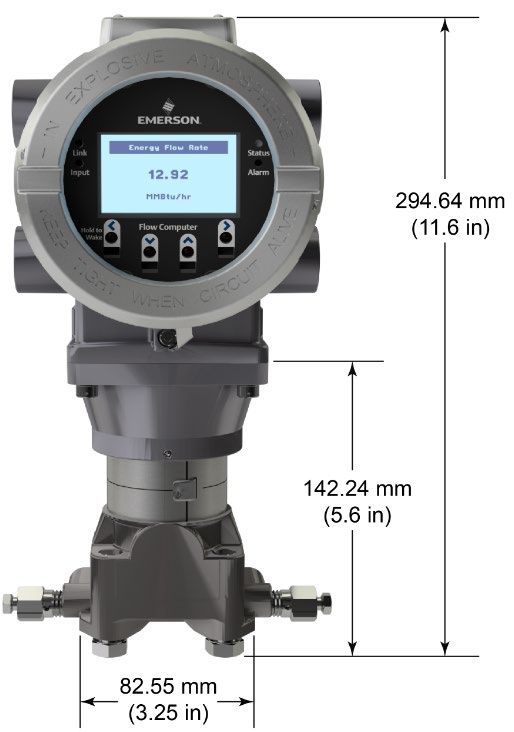
Safe Use Instructions – Emerson FB1100
Part D301768X012
June 2021
Safe Use Instructions – Emerson FB1100 Flow Computer
                                                                                                 Part D301768X012
                                                                                                          June 2021

Emerson FB1100 Flow Computer
                                                               module. See the product data sheet Emerson FB1100 Flow
                                                               Computer (part D301781X012).

         Figure 1. Emerson FB1100 Label (Flameproof)
Use this safe use instructions (SUI) document with the
Emerson FB1100 Flow Computer Instruction Manual (part                Figure 2. Emerson FB1100 Label (Non-sparking)
D301752X012) and the Emerson FB1100 Flow Computer
Quick Start Guide (part D301785X012). For full cautions        Statement of Conformity
and descriptions of installation and troubleshooting           Hereby, Remote Automation Solutions declares that the
procedures, refer to these manuals. If you require training    Emerson FB1100 Flow Computers are in compliance with
for this product, contact your local sales office.             the essential requirements and other relevant provisions
                                                               of European Directives 2014/30/EU (EMC), and
The Emerson FB1100 Flow Computer (or “FB1100”) with            2014/34/EU (ATEX).
ATEX approval may be ordered with an optional factory-
installed interactive display (“HMI module”) or an optional
factory-installed Wi-Fi® (802.11 b/g) communications
Remote Automation Solutions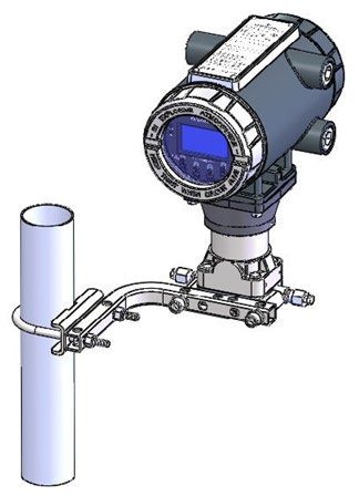
Safe Use Instructions – Emerson FB1100 Flow Computer
Part D301768X012
June 2021
Specific Conditions of Use Specifications
Lead acid battery and solar power options are not for use
in ATEX applications. POWER
Flameproof: Operating Range: 5.7 Vdc to 30 Vdc (10W max power).
Contact your authorized sales and service
representative for any maintenance or repair beyond ENCLOSURE
the routine maintenance of the FB1100 flow
Housing and Caps: Die-cast painted aluminum or
computer. Do not alter or disassemble any of the
optional stainless steel.
fireproof joints of the FB1100 flow computer.
The scalable pressure transmitters provided with the ENVIRONMENTAL
FB1100 flow computers contain a thin‐wall
Operating Temperature:
diaphragm. Installation, maintenance, and use must
Flameproof (Ex db): –40°C to +80°C.
take into account the environmental conditions to
Non-sparking (Ex nA): –40°C to +80°C.
which the diaphragm is subjected. Follow the
Storage Temp.: –40°C to +85°C.
manufacturer’s instructions for installation and Operating Humidity: 5-95% non-condensing per IEC
maintenance to ensure safety during the device’s 60068-2-3.
lifetime.
Refer to Table 1 for replacement parts. WEIGHT
Non-sparking: 6,75 Kg (14.9 lb): Aluminum housing with MVS coplanar
Make provisions to ensure, in the event of transient flange sensor
disturbances, that the rated voltage does not exceed
4,22 Kg (9.3 lb): Aluminum housing without sensor
140% of the peak rated voltage.
13,27 Kg (29.5 lb): Stainless steel housing with MVS
Impact tests on the display were conducted based on coplanar flange sensor
Group II values for the low risk of mechanical danger,
in accordance with Table 13 of both EN APPROVALS
60079‐0:2012+A11:2013 and IEC 60079-0 6th Edition.
Install flow computers with displays in areas where the Evaluated to the following European Standards (EMC):
risk of impact is low. EN 61326-1:2013 (Emissions)
Immunity
Table 1. Replacement Parts EN 61000-4-2 (Electro Static Discharge)
Field Replacement EN 61000-4-3 (Radiated Immunity)
Replacement Part Kit Number Guide document EN 61000-4-4 (Fast Transients)
number EN 61000-4-5 (Surges)
End Caps 399122-01-0 and D301814X012 EN 61000-4-6 (Conducted RF)
(aluminum only) 399123016-KIT EN 61000-4-8 (Power Frequency Magnetic Field)
HMI Module 399379-01-0, D301816X012 EN 61000-4-17 (Voltage Ripple)
Display Assembly 621627011-KIT, EN 61000-4-29 (Voltage Dips and Interrupts)
399380-01-0, Evaluated to the following Approval Standards:
621627020-KIT
Directive 2014/34/EU
CPU Board 399134018-KIT D301802X012 EN 60079-0:2012+A11:2013
Termination Board 399185-01-1, D301820X012 EN 60079-1:2014
and Terminal Block 400216010-KIT, EN 60079-15:2010
395791014-KIT,
395803000-KIT Evaluated to the following Standards (IEC):
Sensor Assembly Variable Kit D301842X012 IEC 60079-0 (2011), 6th Edition
Number IEC 60079-1 (2014), 7th Edition
Coin Cell Battery 395620-03-1 D301854X012
IEC 60079-15 (2010), 4th Edition
Product Markings for Hazardous Locations:
Ex db IIB T4 Gb (–40°C ≤ Tamb ≤ +80°C),
II 2 G
Cert. No. DEMKO 15 ATEX 1349X
Ex nA IIC T4 Gc (–40°C ≤ Tamb ≤ +80°C),
II 3 G.
Cert. No. DEMKO 15 ATEX 1367X
2 www.Emerson.com/RemoteAutomation
Safe Use Instructions – Emerson FB1100 Flow Computer
Part D301768X012
June 2021
DANGER
When installing units in a hazardous area, make sure all
installation components selected are labeled for use in
such areas. Installation and maintenance must be
performed only when the area is known to be non-
hazardous. Installation or maintenance in a hazardous
area could result in personal injury or property damage.
Always turn off the power to the FB1100 before you
attempt any type of wiring. Wiring of powered
equipment could result in personal injury or property
damage.
To avoid circuit damage when working
inside the unit, use appropriate electrostatic discharge
precautions, such as wearing a grounded wrist strap.
Check the input power polarity before connecting power
to the FB1100. Wiring of powered equipment could result
in personal injury or property damage.
The following tools are required for installation,
maintenance, and troubleshooting:
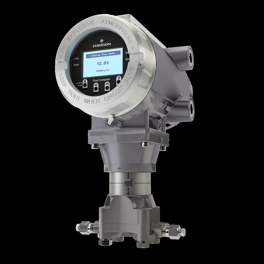
Figure 3. Front View of the FB1100
Personal computer running Microsoft® Windows® 7 (with optional LCD and optional MVS sensor)
Professional or Windows 8.1 Pro, or Windows 10 Pro
and Emerson Field Tools configuration software
(providing FBxConnect™).
#1 and #2 Phillips (cross-head) screwdrivers.
3 mm (1/8-inch) flat-head screwdriver.
Torque wrench.
14 mm (9/16-inch) and 10 mm (3/8-inch) hexagonal
wrenches.
Unpacking
You receive the FB1100 in a box. Remove it from the box.
Examine the packing list carefully to ensure you have all
components.
Installation
1. Find a suitable location for the FB1100. When Figure 4. Side View of the FB1100
selecting an installation site, be sure to check all
clearances. The FB1100 housing is designed to
withstand a variety of inclement conditions. The
optional LCD should be visible and accessible for the
on-site operator.
Figure 5. Top View of the FB1100
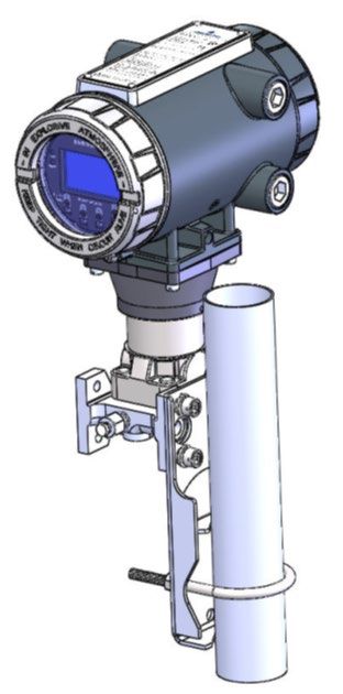
2. The FB1100 mounts either directly to a manifold on
the pipeline or indirectly on a two-inch pipe or pole.
See Figures 6 and 7.
www.Emerson.com/RemoteAutomation 3
Safe Use Instructions – Emerson FB1100 Flow Computer
Part D301768X012
June 2021
uninterrupted electrical path to the service
disconnect.
Improper grounding or poor grounding practices
can often cause problems, such as introducing
ground loops into the system. Properly grounding
the FB1100 helps to reduce the effects of electrical
noise on the unit’s operation and protects against
lightning. Install a surge protection device at the
service disconnect on DC voltage source systems
to protect the installed equipment against
lightning and power surges.
Ensure that the flow computer’s ground is
separate from the cathodic protection ground.
The grounding installation method for the FB1100
depends on whether the pipeline has cathodic
protection. On pipelines with cathodic protection,
Figure 6. FB1100 using Coplanar Mount electrically isolate the FB1100 from the pipeline. All
earth grounds must have an earth-to-ground rod or
grid impedance of 25 ohms or less, as measured with
a ground system tester.
Wiring to Power
Review the power wiring descriptions in Chapter 2 of the
Emerson FB1100 Flow Computer Instruction Manual (part
D301752X012). Wire the FB1100 through the conduit
fittings on the side of the housing. The terminal blocks
accept 2mm in diameter/3mm2 or smaller wiring. To
connect the wire to the removable block compression
terminals:
Bare the end (6mm maximum) of the wire.
Insert the bared end of the wire into the clamp
Figure 7. FB1100 on Pipe Mount beneath the termination screw.
Grounding Tighten the screw.
Remove the front and rear covers of the FB1100 as Expose a minimum of bare wire to prevent short circuits.
detailed in either Chapter 2 of the Emerson FB1100 Flow Allow some slack when making connections to prevent
Computer Instruction Manual (part D301752X012) or in strain.
the Emerson FB1100 Flow Computer Quick Start Guide
(part D301785X012). Store the covers in a secure Verify the hook-up polarity is correct.
location.
To make DC power supply connections:
If your company has no specific grounding Optionally, install a surge protection device at the
requirements, install the FB1100 as a “floating” service disconnect.
(unconnected to ground) system using the ground lug
and routing the ground wire through one of the conduit Install a fuse at the input power source.
fittings. Otherwise, follow your company’s specific Remove the terminal block connector from the
grounding practices. However, if you are making a socket.
connection between a grounded device and an EIA-232
(RS-232) port, ground the FB1100’s power supply Insert each bare wire end into its appropriate
connector and secure the wire (see Figure 8).
If you must ground the equipment, observe the Plug the terminal block connector back into the
following guidelines: socket.
When the equipment uses a DC voltage source,
the grounding system must terminate at the
service disconnect. All equipment grounding
conductors–including wire or conduit carrying the
power supply conductors–must provide an
4 www.Emerson.com/RemoteAutomationSafe Use Instructions – Emerson FB1100 Flow Computer
Part D301768X012
June 2021
Resetting the FB1100
If you are experiencing problems that appear to be
software related, try resetting the FB1100. Refer to the
Service and Troubleshooting chapter of the Emerson
FB1100 Flow Computer Instruction Manual (part
D301752X012) for specific instructions.
Note: You lose all configuration and log data with a
reset. If possible, make a backup of
configuration and log data before attempting
Figure 8. Wiring to DC Power Supply any type of reset.
Wiring to Communications
Replacing Parts in the FB1100
Connect the wiring to the terminal blocks on the
communications module. Refer to either Section 2.13 in Refer to Table 1 for a list of user-serviceable parts and their
Chapter 2 of the Emerson FB1100 Flow Computer respective Field Replacement Guides.
Instruction Manual (part D301752X012) or the Emerson
FB1100 Flow Computer Quick Start Guide (part
Returning the FB1100
D301785X012) for wiring schematics and If you are experiencing problems that appear to be
explanations. hardware-related, verify the wiring. If you still experience
problems, contact your local sales office for return
Once you have wired the communications and I/O, authorization. To return the device:
replace the front and rear covers of the FB1100.
1. Back up all configuration and data before removing
Powering Up the FB1100 the device from process. Then remove power from
the device and remove all external wiring.
DANGER
2. Uninstall the device.
Do not attempt to connect power or disconnect power
from the unit in a hazardous area. Ensure the area is Place the device into a box safe for shipping or storage.
non-hazardous. Failure to do so could result in an
explosion.
To start up the FB1100, apply power.
When you turn power on, the backlight on the HMI
module lights for about 5 seconds, then turns off. During
this time the database begins to initialize. After about 45
seconds the backlight on the HMI turns on again and starts
to display live data.
Periodically inspect the wiring for signs of
deterioration.
Configuring the FB1100
You must install Emerson’s Field Tools configuration
software (which includes FBxConnect™) on your PC to
configure the FB1100 for use. Refer to the Emerson
FB1100 Flow Computer Quick Start Guide (part
D301785X012) for instructions on installing and using
this software.
www.Emerson.com/RemoteAutomation 5Safe Use Instructions – Emerson FB1100 Flow Computer
Part D301768X012
June 2021
For customer service and technical support,
visit www.Emerson.com/SupportNet.
Global Headquarters,
North America, and Latin America:
Emerson Automation Solutions
Remote Automation Solutions
6005 Rogerdale Road
Houston, TX 77072 U.S.A.
T +1 281 879 2699 | F +1 281 988 4445
www.Emerson.com/RemoteAutomation
Europe:
Emerson Automation Solutions
Remote Automation Solutions
Unit 1, Waterfront Business Park
Dudley Road, Brierley Hill
Dudley DY5 1LX UK
T +44 1384 487200
Middle East/Africa:
Emerson Automation Solutions
Remote Automation Solutions
Emerson FZE
P.O. Box 17033 © 2017-2021 Remote Automation Solutions, a business unit of Emerson Automation
Jebel Ali Free Zone – South 2 Solutions. All rights reserved.
Dubai U.A.E.
T +971 4 8118100 | F +971 4 8865465 This publication is for informational purposes only. While every effort has been made to ensure
accuracy, this publication shall not be read to include any warranty or guarantee, express or
Asia-Pacific: implied, including as regards the products or services described or their use or applicability.
Emerson Automation Solutions Remote Automation Solutions (RAS) reserves the right to modify or improve the designs or
Remote Automation Solutions specifications of its products at any time without notice. All sales are governed by RAS terms
1 Pandan Crescent and conditions which are available upon request. RAS accepts no responsibility for proper
Singapore 128461 selection, use or maintenance of any product, which remains solely with the purchaser and/or
T +65 6777 8211| F +65 6777 0947 end-user.
Remote Automation SolutionsAnleitung zur sicheren Verwendung – Emerson FB1100
Dok.-Nr. D301768X012
Juni 2021
Emerson FB1100 Flow Computer
Der Emerson FB1100 Flow Computer (oder “FB1100”) mit
ATEX-Zulassung kann mit einer optionalen
werksmontierten interaktiven Anzeige (HMI-Modul) oder
einem optionalen werksmontierten Wi-Fi® (802.11 b/g)-
Kommunikationsmodul bestellt werden. Siehe
Produktdatenblatt Emerson FB1100 Flow Computer
(Dok.-Nr. D301781X012).
Abbildung 1. Emerson FB1100 Typenschild (druckfeste
Kapselung)
Diese Anleitung zur sicheren Verwendung ergänzt die
Betriebsanleitung für den Emerson FB1100 Flow Computer Abbildung 2. Emerson FB1100 Typenschild (funkenfrei)
(Dok.-Nr. D301752X012) und die Kurzanleitung für den
Emerson FB1100 Flow Computer (Dok.-Nr. D301785X012). Konformitätserklärung
In diesen Handbüchern finden Sie vollständige Remote Automation Solutions erklärt hiermit, dass die
Warnhinweise und Beschreibungen von Verfahren zur Emerson FB1100 Flow Computer den grundlegenden
Installation und Störungsanalyse und -beseitigung. Sollten Anforderungen und anderen relevanten Vorschriften der
Sie für dieses Produkt eine Schulung benötigen, wenden EU-Richtlinien 2014/30/EU (EMV) und 2014/34/EU (ATEX)
Sie sich bitte an Ihr örtliches Vertriebsbüro. entsprechen.
Remote Automation SolutionsAnleitung zur sicheren Verwendung – Emerson FB1100
Dok.-Nr. D301768X012
Juni 2021
Spezielle Voraussetzungen für die Verwendung
Technische Daten
Lithiumbatterien, Bleisäurebatterien und Solarenergie-
optionen sind nicht für ATEX-Anwendungen bestimmt. SPANNUNGSVERSORGUNG
Druckfeste Kapselung: Betriebsbereich: 5,7 VDC bis 30 VDC (10 W max. Strom)
Wenden Sie sich bei Wartungs- oder Reparaturanliegen, GEHÄUSE
die über die Routinewartung des Durchflusscomputers
FB1100 hinausgehen, an Ihren autorisierten Vertriebs- Gehäuse und Deckel: Druckguss-Aluminium oder
und Kundendienstpartner. Nehme Sie keine optional Edelstahl.
Änderungen an den feuerfesten Gelenken des UMGEBUNGSBEDINGUNGEN
Durchflusscomputers FB1100 vor und bauen Sie sie
nicht auseinander. Betriebstemperatur:
Druckfeste Kapselung (Ex db): –40 °C bis +80 °C.
Die mit den Durchflusscomputern FB1100 gelieferten
Funkenfrei (Ex nA): –40 °C bis +80 °C.
skalierbaren Druckmessumformer enthalten eine
Lagertemperatur: –40 °C bis +85 °C.
dünnwandige Membran. Bei der Installation, Wartung
Betriebsluftfeuchtigkeit: 5 - 95 % nicht kondensierend
und Verwendung müssen die gemäß IEC 60068-2-3.
Umgebungsbedingungen, denen die Membran
ausgesetzt ist, beachtet werden. Halten Sie sich an die GEWICHT
Wartungs- und Installationsanweisungen des 6,75 Kg (14.9 lb): Aluminiumgehäuse mit MVS-Coplanar-
Herstellers, um die Sicherheit während der Flansch-Sensor
Gerätelebensdauer zu gewährleisten.
4,22 Kg (9.3 lb): Aluminiumgehäuse ohne Sensor
Für Ersatzteile siehe Tabelle 1.
13,27 Kg (29.5 lb): Edelstahlgehäuse mit MVS-Coplanar-
Funkenfrei: Flansch-Sensor
Treffen Sie Vorbereitungen, damit die Nennspannung
ZULASSUNGEN
im Falle einer kurzzeitigen Störung 140 % der
Spitzennennspannung nicht überschreitet. Bewertet gemäß folgenden europäischen Normen (EMV):
In Übereinstimmung mit Tabelle 13 aus EN 61326-1:2013 (Emissionen)
EN 60079-0:2012+A11:2013 und IEC 60079-0, 6. Immunität
Ausgabe, wurden basierend auf Gruppe-II-Werten für EN 61000-4-2 (elektrostatische Entladung)
EN 61000-4-3 (Störstrahlungsimmunität)
geringes Risiko mechanischer Gefährdung
EN 61000-4-4 (Schnelle Transienten)
Schlagprüfungen auf dem Display durchgeführt.
EN 61000-4-5 (Stoßspannungen)
Bringen Sie Durchflusscomputer so an, dass die
EN 61000-4-6 (Geleitete RF)
Displays einem geringen Schlagrisiko ausgesetzt sind. EN 61000-4-8 (Magnetfeld bei Nennfrequenz)
Ersatzteile finden Sie in Tabelle 1. EN 61000-4-17 (Spannungswelligkeit)
EN 61000-4-29 (Spannungseinbrüche und
Tabelle 1. Ersatzteile Unterbrechungen)
Feldersatzanleitung- Bewertet gemäß den folgenden Zulassungsstandards:
Ersatzteil Teilesatznummer
Dokumentnummer Richtlinie 2014/34/EU
Endkappen 399122-01-0 and D301814X012 EN 60079-0:2012+A11:2013
(nur Aluminium) 399123016-KIT EN60079-1:2014
HMI-Modul- 399379-01-0, D301816X012 EN 60079-15:2010
Bedieninterface 621627011-KIT,
399380-01-0, Bewertet gemäß den folgenden Standards (IEC):
621627020-KIT IEC 60079-0 (2011), 6. Ausgabe
CPU-Platine 399134018-KIT D301802X012 IEC 60079-1 (2014), 7 Ausgabe
Anschlussplatine und 399185-01-1, D301820X012 IEC 60079-15 (2010), 4. Ausgabe
Anschlussklemmenblock 400216010-KIT,
395791014-KIT, Produktkennzeichnungen für Gefahrenbereiche:
395803000-KIT Ex db IIB T4 Gb (–40 °C ≤ Tamb ≤ +80 °C)
Sensorbaugruppe Variablensatznummer D301842X012
Knopfzellenbatterie 395620-03-1 D301854X012 II 2 G
Zert. Nr. DEMKO 15 ATEX 1349X
Ex nA IIC T4 Gc (–40 °C ≤ Tamb ≤ +80 °C)
II 3 G
Zert. Nr. DEMKO 15 ATEX 1367X
2 www.Emerson.com/RemoteAutomationAnleitung zur sicheren Verwendung – Emerson FB1100
Dok.-Nr. D301768X012
Juni 2021
GEFAHR
Wenn Geräte in einem explosionsgefährdeten Bereich
installiert werden, muss darauf geachtet werden, dass
alle ausgewählten Installationskomponenten für den
Einsatz in solchen Bereichen zugelassen sind.
Installations- und Wartungsarbeiten dürfen nur dann
durchgeführt werden, wenn der Arbeitsbereich nicht in
einem Ex-Bereich liegt. Installations- und
Wartungsarbeiten in einem Ex-Bereich können zu
Personen- und/oder Sachschäden führen.
Vor der Verkabelung des Gerätes stets die externe
Spannungsversorgung vom FB1100 trennen. Die
Verkabelung eines mit Spannung versorgten Gerätes
kann zu Personen- und/oder Sachschäden führen.
Um elektrische Schäden bei Arbeiten im Geräteinneren zu
vermeiden, müssen die erforderlichen Vor-sichts-maß-
nah-men zur Vermeidung elektrostatischer Entladungen
eingehalten werden, zum Beispiel durch das Tragen eines
Antistatikbands.
Vor dem Einschalten der Spannungsversorgung des Abbildung 3. Frontansicht des FB1100
FB1100 die Polarität des Eingangsstroms prüfen. Die (mit optionaler LCD-Anzeige)
Verkabelung eines mit Spannung versorgten Gerätes kann
zu Personen- und/oder Sachschäden führen.
Für Installation, Wartung sowie Störungsanalyse und -
beseitigung sind die folgenden Hilfsmittel bzw.
Werkzeuge erforderlich:
PC mit Microsoft® Windows® 7 Professional, Windows
8.1 Pro oder Windows 10 Pro und der Emerson Field
Tools Konfigurationssoftware (mit FBxConnect™)
Kreuzschlitzschraubendreher Nr. 1 und Nr. 2
Schlitzschraubendreher 3 mm (1/8 in.)
Drehmomentschlüssel.
14 mm (9/16-inch) und 10 mm (25/64-inch)
Sechskantschlüssel.
Auspacken Abbildung 4. Seitenansicht des FB1100
Der FB1100 wird in einem Karton geliefert. Nehmen Sie
ihn aus dem Karton. Prüfen Sie die Packliste sorgfältig, um
sicherzustellen, dass Sie alle Komponenten zur Hand
haben.
Einbau
1. Einen geeigneten Standort für den FB1100 wählen.
Bei der Auswahl eines Einbauortes alle Abstände
prüfen. Das Gehäuse des FB1100 widersteht einer
Reihe von rauen Bedingungen. Die optionale LCD-
Anzeige sollte für den Bediener vor Ort sichtbar und
zugänglich sein. Abbildung 5. Draufsicht des FB1100
2. Der FB1100 wird entweder direkt am Ventilblock oder
an der Rohrleitung (mit einer Coplanar-Befestigung)
oder indirekt an einer Leitung oder einem Pfosten mit
zwei Zoll angebracht. Siehe Abbildungen 6 und 7.
www.Emerson.com/RemoteAutomation 3Anleitung zur sicheren Verwendung – Emerson FB1100
Dok.-Nr. D301768X012
Juni 2021
Spannungseinspeisung abgeschlossen werden.
Alle Geräteerdungsleiter – einschließlich Kabel
oder in Kabelrohr verlegte Spannungs-ver-sor-
gungs-lei-ter – müssen einen ununterbrochenen
elektrischen Pfad zur Spannungseinspeisung
bilden.
Unsachgemäße oder schlechte Erdung kann oft
Probleme verursachen, wie z. B. Erdschleifen im
System. Eine sachgemäße Erdung des FB1100
kann dazu beitragen, Einflüsse durch elektrisches
Rauschen auf den Betrieb des FB1100 zu
minimieren, und schützt vor
Überspannungen/Blitzschlag. Installieren Sie eine
Überspannungsschutzvorrichtung am
Betriebsunterbrecher in DC-Spannungs-quellen-
sys-te-men, um die installierte Ausrüstung vor
Abbildung 6. FB1100 mit Coplanar-Befestigung Blitzschlag und Stromstößen zu schützen.
Stellen Sie sicher, dass die Erdung des Flow
Computers vom kathodischen Schutz getrennt ist.
Die Ausführung der Erdungsinstallation für den
FB1100 hängt davon ab, ob die Rohrleitung über
einen kathodischen Schutz verfügt. Bei Rohrleitungen
mit kathodischem Schutz muss der FB1100 elektrisch
von der Rohrleitung isoliert bleiben. Alle
Schutzerdungen müssen eine Erdungsverbindung
oder eine Netzimpedanz von 25 Ohm oder weniger
aufweisen; die Messung ist mit einem Erdungstester
vorzunehmen.
Verkabelung der Spannungsversorgung
Die Beschreibungen für die Verdrahtung der
Spannungsversorgung in Kapitel 2 der Bedienungsanleitung
Abbildung 7. FB1100 mit Rohrbefestigung
für den Emerson FB1100 Flow Computer (Dok.-Nr.
Erdung D301752X012) gründlich lesen. Den FB1100 durch die
Leitungseinführungen an der Seite des Gehäuses
Die vorderen und hinteren Deckel des FB1100 gemäß verdrahten. Die Anschlussklemmenblöcke akzeptieren
entweder Kapitel 2 der Bedienungsanleitung für den eine Verkabelung mit 2 mm Durchmesser/3 mm2 oder
Emerson FB1100 Flow Computer (Dok.-Nr. kleiner. Anschluss der Leiter an die abnehmbare
D301752X012) oder der Kurzanleitung für den Emerson Klemmenleiste:
FB1100 Flow Computer (Dok.-Nr. D301785X012) Das Ende des Drahtes abisolieren (maximal 6 mm).
entfernen. Die Deckel an einem sicheren Ort
aufbewahren. Das abisolierte Ende des Drahtes in die Klemme
unterhalb der Klemmschraube einführen.
Wenn es in Ihrem Unternehmen keine speziellen
Die Schraube festziehen.
Erdungsvorschriften gibt, installieren Sie den FB1100
als ein „potentialfreies“ (ungeerdetes) System mittels
Lassen Sie so wenig blanke Kabelenden wie möglich offen,
des Erdungsanschlusses und führen Sie das
um Kurzschlüsse zu verhindern. Lassen Sie bei der
Erdungskabel durch eine der Kabelverschraubungen.
Herstellung der Verbindungen etwas Spiel, um
Andernfalls die speziellen Erdungsverfahren Ihres
Spannungen zu vermeiden.
Unternehmens beachten. Wenn Sie eine Verbindung
zwischen einem geerdeten Gerät und einem EIA-232 Anschluss auf richtige Polarität überprüfen.
(RS-232)-Anschluss herstellen, müssen Sie die
Spannungsversorgung des FB1100 erden. Anschlüsse zur Gleichspannungsversorgung herstellen:
Wenn das Gerät geerdet werden muss, sind die Optional einen Überspannungsschutz an der
folgenden Richtlinien zu beachten: Spannungseinspeisung installieren.
Wenn das Gerät mit einer Gleichspannungsquelle Die Eingangsspannungsquelle mit einer Sicherung
versorgt wird, muss die Erdung an der absichern.
4 www.Emerson.com/RemoteAutomationAnleitung zur sicheren Verwendung – Emerson FB1100
Dok.-Nr. D301768X012
Juni 2021
Den Stecker des Anschlussklemmenblocks von der Konfigurieren des FB1100
Steckdose trennen.
Sie müssen die Field Tools Konfigurationssoftware von
Jedes blanke Kabelende in den entsprechenden Emerson (die FBxConnect™ mit einschließt) auf Ihrem
Anschluss einführen und sichern (siehe Abbildung 8). PC installieren, um den FB1100 für den Einsatz zu
Den Stecker des Anschlussklemmenblocks wieder in konfigurieren. Anweisungen zur Installation und
die Steckerleiste einsetzen. Verwendung dieser Software finden Sie in der
Kurzanleitung für den Emerson FB1100 Flow Computer
(Dok.-Nr. D301785X012).
Zurücksetzen des FB1100
Falls Probleme auftreten, deren Ursache in der
Software vermutet wird, versuchen Sie, den FB1100
zurückzusetzen. Spezifische Anweisungen hierzu
finden Sie im Kapitel Service und Fehlersuche der
Betriebsanleitung für den Emerson FB1100 Flow
Computer (Dok.-Nr. D301752X012).
Hinweis: Beim Zurücksetzen gehen alle
Konfigurations- und Protokolldaten
Abbildung 8. Verkabelung zur DC-Spannungsversorgung verloren. Erstellen Sie (falls möglich) eine
Sicherheitskopie der Konfigurations- und
Verkabelung mit Kommunikation Protokolldaten, bevor Sie versuchen, das
Gerät zurückzusetzen.
Schließen Sie die Verkabelung an den Anschluss-klem-
men-blöcke der Kom-mu-ni-kations-mo-du-le an. Die Austausch von Ersatzteilen im FB1100
Schaltpläne und Erläuterungen finden Sie entweder in
Kapitel 2, Abschnitt 2.13 der Bedienungsanleitung für den Eine Liste der Teile, die der Benutzer selbst warten kann,
Emerson FB1100 Flow Computer (Dok.-Nr. und ihre entsprechenden Feldersatzanleitungen finden Sie
D301752X012) oder in der Kurzanleitung für den Emerson in Tabelle 1.
FB1100 Flow Computer (Dok.-Nr. D301785X012).
Zurücksenden des FB1100
Wenn Sie die Kommunikation und die E/A verkabelt
haben, bringen Sie die vorderen und hinteren Deckel Falls Probleme auftreten, deren Ursache in der Hardware
wieder am FB1100 an. vermutet wird, die Verkabelung prüfen. Falls die Probleme
weiterhin bestehen, wenden Sie sich zur Autorisierung der
Einschalten des FB1100 Rückgabe an Ihr lokales Vertriebsbüro. So geben Sie Ihr
Gerät zurück:
GEFAHR 1. Alle Konfigurationen und Daten sichern, bevor das
Versuchen Sie nicht, dem Gerät Spannung zuzuführen Gerät aus dem Prozess entfernt wird. Dann alle
oder es von der Spannungsversorgung zu trennen, Spannungsquellen vom Gerät trennen und die externe
während es sich in einem Ex-Bereich befindet. Verkabelung vollständig entfernen.
Vergewissern Sie sich, dass die Umgebung nicht 2. Gerät deinstallieren.
gefährlich ist. Bei Nichtbeachtung kann es zu einer
Explosion kommen. 3. Für den Versand oder die Lagerung das Gerät in einen
Karton legen.
Spannung zuführen, um den FB1100 einzuschalten.
Wenn Sie die Spannungsversorgung einschalten, leuchtet
die Hintergrundbeleuchtung am HMI-Modul ca. 5
Sekunden lang auf und erlischt wieder. Während dieser
Zeit wird die Datenbank initialisiert. Nach ca. 45 Sekunden
schaltet sich die Hintergrundbeleuchtung am HMI wieder
ein und beginnt, Live-Daten anzuzeigen.
Überprüfen Sie die Verkabelung regelmäßig auf
Anzeichen von Verschleiß.
www.Emerson.com/RemoteAutomation 5Anleitung zur sicheren Verwendung – Emerson FB1100
Dok.-Nr. D301768X012
Juni 2021
Kundendienst und technische Unterstützung
finden Sie unter www.Emerson.com/SupportNet.
Weltweite Firmenzentrale
Nordamerika/Lateinamerika:
Emerson Automation Solutions
Remote Automation Solutions
6005 Rogerdale Road
Houston, TX 77072, USA
Tel.: +1 281 879 2699 | Fax: +1 281 988 4445
www.Emerson.com/RemoteAutomation
Europa:
Emerson Automation Solutions
Remote Automation Solutions
Unit 1, Waterfront Business Park
Dudley Road, Brierley Hill
Dudley DY5 1LX UK
Tel.: +44 1384 487200
Naher Osten/Afrika:
Emerson Automation Solutions © 2017-2021 Remote Automation Solutions, ein Geschäftsbereich von Emerson
Remote Automation Solutions Automation Solutions. Alle Rechte vorbehalten.
Emerson FZE
P.O. Box 17033 Diese Publikation dient nur zu Informationszwecken. Obwohl große Sorgfalt zur
Jebel Ali Free Zone – South 2 Gewährleistung ihrer Exaktheit aufgewendet wurde, kann diese Publikation nicht zur
Dubai, Vereinigte Arabische Emirate Ableitung von Garantie- oder Gewährleistungsansprüchen, ob ausdrücklicher Art oder
Tel.: +971 4 8118100 | Fax: +971 4 8865465 stillschweigend, hinsichtlich der in dieser Publikation beschriebenen Produkte oder
Dienstleistungen oder ihres Gebrauchs oder ihrer Verwendbarkeit herangezogen werden.
Asien/Pazifik: Remote Automation Solutions (RAS) behält sich das Recht vor, jederzeit und ohne
Emerson Automation Solutions Vorankündigung die Konstruktion und technischen Daten seiner Produkte zu ändern oder
Remote Automation Solutions zu verbessern. Für alle Verkäufe gelten unsere (RAS) allgemeinen Geschäftsbedingungen,
1 Pandan Crescent die auf Anfrage zur Verfügung gestellt werden. Die Verantwortung bezüglich der richtigen
Singapur 128461 Auswahl, Verwendung oder Wartung von jeglichen Produkten liegt allein beim Käufer und
Tel.: +65 6777 8211| Fax: +65 6777 0947 Endanwender.
Remote Automation SolutionsConsignes de sécurité – Emerson FB1100
réf. D301768X012
Juin 2021
Calculateur de débit Emerson FB1100
indicateur interactif optionnel installé en usine (« module
HMI ») ou un module de communication Wi-Fi®
(802.11 b/g) optionnel installé en usine. Consultez la fiche
de spécifications du Calculateur de débit Emerson FB1100
(réf. D301781X012).
Figure 1. Étiquette Emerson FB1100 (antidéflagrant)
Utilisez les présentes Instructions d'utilisation et de
sécurité conjointement avec le Manuel d'instructions du
calculateur de débit Emerson FB1100 (réf. D301752X012) et Figure 2. Étiquette Emerson FB1100 (anti-étincelles)
le Guide de démarrage rapide du calculateur de débit
Emerson FB1100 (réf. D301785X012). Consultez ces Déclaration de conformité
manuels pour obtenir toutes les mesures de précaution, Remote Automation Solutions déclare par la présente que
instructions d'installation et procédures de dépannage. les calculateurs de débit FB1100 sont conformes aux
Pour obtenir une formation relative à ce produit, exigences essentielles et aux autres dispositions
contactez un bureau commercial Emerson local. applicables des Directives européennes 2014/30/UE (CEM)
Le calculateur de débit Emerson FB1100 (ou « FB1100 ») et 2014/34/EU (ATEX).
avec homologation ATEX peut être commandé avec un
Remote Automation SolutionsConsignes de sécurité – Emerson FB1100
réf. D301768X012
Juin 2021
Conditions particulières d’utilisation
Spécifications
Les batteries au lithium, les batteries au plomb-acide et
l’énergie solaire ne doivent pas être utilisées dans des ALIMENTATION
applications ATEX. Plage de fonctionnement : 5,7 à 30 V cc (puissance maximale
Antidéflagrant : de 10 W).
BOITIER
▪ Contacter le représentant commercial ou de l’entretien
habilité pour toute opération de maintenance ou Boîtier et capuchons : Aluminium laqué moulé sous pression
réparation qui ne concerne pas la maintenance ou acier inoxydable en option.
préventive du calculateur de débit FB1100. Ne pas
ENVIRONNEMENT
modifier ou démonter les joints ignifuges du
calculateur de débit FB1100. Température de fonctionnement :
Antidéflagrant (Ex db) : -40 °C à +80 °C.
▪ Les transmetteurs de pression modulaire fournis avec Anti-étincelle (Ex nA) : -40 °C à +80 °C.
le calculateur de débit FB1100 sont équipés d’une Température. de stockage : -40 °C à +85 °C.
membrane fine. L’installation, la maintenance et Humidité de fonctionnement : 5-95 % sans condensation,
l’utilisation doivent tenir compte de l’environnement conformément à la norme CEI 60068-2-3.
auquel la membrane est soumise. Afin de garantir la
POIDS
sécurité tout au long de la durée de vie de l’appareil,
suivre les instructions du fabricant concernant 6,75 Kg (14.9 lb): Boîtier en aluminium avec capteur à bride
l’installation et la maintenance. coplanaire MVS
▪ Consulter le tableau 1 pour les pièces de rechange. 4,22 Kg (9.3 lb): Boîtier en aluminium avec capteur
Anti-étincelles : 13,27 Kg (29.5 lb): Boîtier en aluminium en acier inoxydable
avec capteur à bride coplanaire MVS
▪ Prendre les précautions nécessaires pour s’assurer, en
cas de perturbation transitoire, que la tension HOMOLOGATIONS
nominale ne dépasse pas 140 % de la tension nominale
Évalué par rapport aux normes européennes suivantes (CEM) :
de crête. EN 61326-1:2013 (Émissions)
▪ Des tests d’impact sur l’écran ont été menés en Immunité
fonction des valeurs du Groupe II portant sur le faible EN 61000-4-2 (Décharge électrostatique)
risque de danger mécanique, conformément au EN 61000-4-3 (Immunité aux champs rayonnés)
tableau 13 des normes EN 60079-0:2012+A11:2013 et EN 61000-4-4 (Immunité aux transitoires rapides en
salves)
CEI 60079-0 (6e édition). Installer les calculateurs de
EN 61000-4-5 (Surtensions)
débit équipés d’un écran dans des zones où le risque EN 61000-4-6 (Immunité aux radiofréquences
d’impact est faible. conduites)
▪ Consulter le tableau 1 pour les pièces de rechange. EN 61000-4-8 (Immunité aux champs magnétiques de
puissance à impulsions)
Tableau 1. Pièces de rechange EN 61000-4-17 (Immunité aux ondulations de tension)
Numéro de EN 61000-4-29 (Immunité aux chutes et interruptions
document du de tension)
Pièce de rechange Référence du kit Guide de Évalué par rapport aux normes d'homologation suivantes :
remplacement sur Directive 2014/34/UE
le terrain EN 60079-0:2012+A11:2013
EN 60079-1:2014
Capuchons 399122-01-0 and D301814X012
EN 60079-15:2010
d'extrémité 399123016-KIT
(aluminium Évalué par rapport aux normes suivantes (CEI) :
uniquement) CEI 60079-0 (2011), 6e édition
Indicateur du 399379-01-0, D301816X012 CEI 60079-1 (2014), 7e édition
module HMI 621627011-KIT, CEI 60079-15 (2010), 4e édition
399380-01-0,
621627020-KIT Marquages de produit pour emplacements dangereux :
Ex db IIB T4 Gb (-40 °C ≤ Tamb ≤ +80 °C)
Carte d'unité 399134018-KIT D301802X012
centrale CPU
II 2 G
Carte de 399185-01-1, D301820X012 Cert. n° DEMKO 15 ATEX 1349X
terminaison et 400216010-KIT,
bornier 395791014-KIT, Ex nA IIC T4 Gc (-40 °C ≤ Tamb ≤ +80 °C)
395803000-KIT
Sonde Numéro de kit D301842X012 II 3 G
variable Cert. n°. DEMKO 15 ATEX 1367X
Pile bouton 395620-03-1 D301854X012
2 www.Emerson.com/RemoteAutomationConsignes de sécurité – Emerson FB1100
réf. D301768X012
Juin 2021
DANGER
Si les dispositifs sont installés dans une zone dangereuse,
assurez-vous que les étiquettes des composants
sélectionnés autorisent leur usage dans une telle zone.
L'installation et l'entretien doivent être effectués
uniquement lorsqu'il est certain que la zone ne présente
aucun risque. L'installation ou la maintenance dans une
zone dangereuse peuvent entraîner des blessures ou des
dégâts matériels.
Mettez toujours le FB1100 hors tension avant toute
intervention sur le câblage. Toute intervention sur un
équipement sous tension pourrait entraîner des
blessures ou des dégâts matériels.
Pour éviter d'endommager les circuits lors d'une
intervention à l'intérieur de l'appareil, prenez les
précautions pertinentes concernant les décharges
électrostatiques, notamment le port d'un bracelet
antistatique.
Vérifiez la polarité de l'alimentation en entrée avant de
mettre le FB1100 sous tension. Toute intervention sur un Figure 3. Vue avant du FB1100
équipement sous tension pourrait entraîner des blessures (avec indicateur LCD en option)
ou des dégâts matériels.
Les outils suivants sont nécessaires pour l'installation,
la maintenance et le dépannage :
Ordinateur PC exécutant Microsoft® Windows® 7
Professional, Windows 8.1 Pro ou Windows 10 Pro et
le logiciel de configuration Emerson Field Tools (avec
logiciel de configuration FBxConnect™).
Tournevis Philips (cruciformes) n° 1 et n° 2.
Tournevis à tête plate de 3 mm (1/8-inch).
Clé dynamométrique.
Clés hexagonales 14 mm (9/16-inch) et 10 mm
(25/64-inch).
Déballage Figure 4. Vue latérale du FB1100
Le FB1100 vous est livré dans un carton. Retirez-le de
l'emballage. Vérifiez soigneusement que toutes les pièces
figurant sur le bordereau de livraison sont incluses.
Installation
1. Trouvez un emplacement convenable pour le FB1100.
Lors de la sélection d'un emplacement, assurez-vous
de bien vérifier tous les dégagements. Le boîtier du
FB1100 est conçu pour résister aux mauvaises
conditions climatiques. L'écran LCD en option doit
être visible et accessible pour l'opérateur sur place.
Figure 5. Vue de dessus du FB1100
2. Le FB1100 se monte directement sur un manifold
installé sur la tuyauterie (au moyen d'un montant
Coplanar), ou indirectement sur un tuyau ou un
poteau. Reportez-vous aux Figures 6 et 7.
www.Emerson.com/RemoteAutomation 3Consignes de sécurité – Emerson FB1100
réf. D301768X012
Juin 2021
notamment les fils ou les conduits reliant les
conducteurs, doivent assurer un trajet électrique
ininterrompu jusqu'au sectionneur d'entretien.
Une mise à la terre incorrecte ou médiocre peut
souvent être à l'origine de problèmes tels que
l'introduction de boucles de terre dans le système.
La mise à la terre correcte du FB1100 permet de
réduire les effets du bruit électrique sur le
fonctionnement du dispositif et assure la
protection contre la foudre. Sur les systèmes
d'alimentation en courant continu, installez un
dispositif de protection contre les surtensions au
niveau de l'interrupteur de sectionnement pour
protéger l'équipement contre la foudre et les
surtensions.
Assurez-vous que la terre du calculateur de débit
Figure 6. FB1100 avec montant Coplanar est séparée de la terre de protection cathodique.
La méthode de mise à la terre du FB1100 diffère selon
que la conduite est ou non pourvue d'une protection
cathodique. Sur les conduites pourvues de protection
cathodique, isolez électriquement le FB1100 de la
conduite. Toutes les prises de terre doivent avoir une
impédance de tige ou de grille de mise à la terre
inférieure ou égale à 25 ohms, conformément aux
mesures effectuées à l'aide d'un dispositif d'essai de la
mise à la terre.
Câblage à l'alimentation
Examinez les descriptions de câblage d'alimentation
figurant au Chapitre 2 du Manuel d'instructions du
calculateur de débit Emerson FB1100 (réf. D301752X012).
Câblez le FB1100 via les raccords de conduit situés sur le
Figure 7. FB1100 monté sur tuyau
côté du boîtier. Les borniers sont compatibles avec des
Mise à la terre câbles de 2 mm de diamètre/3 mm2 maximum. Pour
raccorder le fil aux bornes de compression amovibles des
Retirez les couvercles avant et arrière du FB1100, tel borniers :
qu'expliqué au Chapitre 2 du Manuel d'instructions du Dénudez l'extrémité du câble (sur 6 mm maximum).
calculateur de débit Emerson FB1100 (réf.
D301752X012) ou du Guide de démarrage rapide du Introduisez l'extrémité dénudée du câble dans le
calculateur de débit Emerson FB1100 (réf. collier situé sous la vis de terminaison.
D301785X012). Rangez les couvercles en lieu sûr. Serrez la vis.
Si votre site n'observe aucune exigence de mise à la
Veillez à ce qu'une longueur minimale de fil dénudé soit
terre particulière, installez le FB1100 en tant que
exposée afin d'éviter les courts-circuits. Laissez un peu de
système « flottant » (non relié à la terre) à l'aide du plot
mou pour éviter toute tension du câble.
de terre et acheminez le fil de terre via l'un des raccords
de conduit. Dans le cas contraire, observez les pratiques Vérifiez que la polarité de raccordement est correcte.
spécifiques de mise à la terre de votre site. Cependant,
en cas de connexion entre un appareil mis à la terre et Pour les raccordements d'alimentation CC :
un port EIA-232 (RS-232), reliez l'alimentation du Installez, si vous le souhaitez un dispositif de
FB1100 à la terre. protection contre les surtensions au niveau du
sectionneur d'entretien.
Si vous devez mettre l'équipement à la terre, observez
les directives suivantes. Installez un fusible au niveau de la source
Si l'équipement fonctionne sur une source d'alimentation en entrée.
d'alimentation CC, le système de mise à la terre doit se Déposez le connecteur de bornier de son support.
terminer au niveau du sectionneur d'entretien. Tous les
conducteurs de mise à la terre de l'équipement, et
4 www.Emerson.com/RemoteAutomationConsignes de sécurité – Emerson FB1100
réf. D301768X012
Juin 2021
Insérez chaque extrémité de fil dénudé dans le Configuration du FB1100
connecteur correspondant et fixez le câble (reportez-
vous à la Figure 8). Pour configurer le FB1100 à des fins d'utilisation, vous
devez installer le logiciel de configuration Field Tools
Ré-enfichez le connecteur de bornier de son support. d'Emerson (avec FBxConnect™) sur votre ordinateur.
Pour des instructions concernant l'installation et
l'utilisation de ce logiciel, reportez-vous au Guide de
démarrage rapide du calculateur de débit Emerson
FB1100 (réf. D301785X012).
Réinitialisation du FB1100
Face à des problèmes potentiellement liés au logiciel,
essayez de réinitialiser le FB1100. Pour des instructions
spécifiques, reportez-vous au chapitre Entretien et
dépannage du Manuel d'instructions du calculateur de
débit Emerson FB1100 (réf. D301752X012).
Remarque : Une réinitialisation entraînera la perte de
Figure 8. Câblage vers l'alimentation c.c. toutes les données de configuration et de
journalisation. Si possible, sauvegardez
Câblage vers les modules de communication les données de configuration et de
Reliez les câbles aux borniers du module de journalisation avant de procéder à une
communication. Pour le schéma de câblage et des réinitialisation, quelle qu'elle soit.
explications, reportez-vous à la Section 2.13 du chapitre
2 du Manuel d'instructions du calculateur de débit Remplacement des pièces du FB1100
Emerson FB1100 (réf. D301752X012) ou du Guide de Reportez-vous au tableau 1 pour une liste des pièces
démarrage rapide du calculateur de débit Emerson FB1100 réparables par l'utilisateur et de leurs guides de
(réf. D301785X012). remplacement de champ respectifs.
Une fois que vous avez câblé les modules de
communication et d'E/S, remettez en place les
Renvoi du FB1100
couvercles avant et arrière du FB1100. En cas de problèmes potentiellement liés au matériel,
vérifiez le câblage. Si les problèmes persistent, contactez
Mise sous tension du FB1100 votre bureau de vente local pour l'autorisation de renvoi.
Pour renvoyer l'appareil :
DANGER
1. Sauvegardez la configuration et toutes les données
En zone dangereuse, ne cherchez pas à connecter ou à avant de débrancher l'appareil de la boucle de
déconnecter l'alimentation de l'appareil. Assurez-vous procédé. Mettez l'appareil hors tension et
que la zone n'est pas dangereuse pour éviter toute déconnectez tout câblage extérieur.
explosion.
2. Désinstallez l'appareil.
Pour démarrer le FB1100, mettez-le sous tension. 3. Placez l'appareil dans une boîte à des fins d'expédition
ou de stockage.
Lorsque vous appliquez l'alimentation, le rétroéclairage du
module HMI s'allume pendant 5 secondes environ, puis
s'éteint. La base de données commence à s'initialiser
pendant ce temps. Au bout de 45 secondes environ, le
rétroéclairage du HMI s'allume à nouveau et affiche des
données en temps réel.
Inspectez régulièrement le câblage afin de détecter
tout signe de détérioration.
www.Emerson.com/RemoteAutomation 5Consignes de sécurité – Emerson FB1100
réf. D301768X012
Juin 2021
Pour contacter le service clientèle et bénéficier d'une assistance technique,
consultez la page www.Emerson.com/SupportNet.
Siège social international
Amérique du Nord et Amérique latine :
Emerson Automation Solutions
Remote Automation Solutions
6005 Rogerdale Road
Houston, TX 77072 États-Unis.
T +1 281 879 2699 | F +1 281 988 4445
www.Emerson.com/RemoteAutomation
Europe :
Emerson Automation Solutions
Remote Automation Solutions
Unit 1, Waterfront Business Park
Dudley Road, Brierley Hill
Dudley DY5 1LX UK
T +44 1384 487200
Moyen-Orient/Afrique :
Emerson Automation Solutions
Remote Automation Solutions
Emerson FZE
P.O. Box 17033 © 2017-2021 Remote Automation Solutions, une division d'Emerson Automation Solutions.
Jebel Ali Free Zone – South 2 Tous droits réservés.
Dubai, Émirats Arabes Unis.
T +971 4 8118100 | F +971 4 8865465 Cette publication est à titre informatif uniquement. Bien que tous les efforts aient été faits pour
vérifier l'exactitude des informations présentées dans ce document, ce dernier ne saurait être
Asie-Pacifique : considéré comme une garantie tacite ou explicite des produits ou services décrits quant à leur
Emerson Automation Solutions utilisation ou leur applicabilité. Remote Automation Solutions (RAS) se réserve le droit de
Remote Automation Solutions modifier ou d'améliorer les conceptions ou les spécifications de ses produits à tout moment et
1 Pandan Crescent sans préavis. Toutes les ventes sont régies par les conditions générales de RAS, lesquelles sont
Singapour 128461 disponibles sur demande. RAS décline toute responsabilité quant au choix, à l'utilisation ou à
T +65 6777 8211| F +65 6777 0947 l'entretien d'un produit, laquelle incombe uniquement à l'acquéreur ou à l'utilisateur final.
Remote Automation SolutionsInstruções para uso seguro – Emerson FB1100
Peça D301768X012
Junho de 2021
Computador de vazão Emerson FB1100
interativo instalado em fábrica opcional ("módulo HMI") ou
um módulo de comunicações Wi-Fi® (802.11 b/g)
instalado em fábrica opcional. Consulte a folha de dados
do produto do Computador de vazão Emerson FB1100
(peça D301781X012).
Figura 1. Etiqueta Emerson FB1100 (à prova de chamas)
Use este documento de Instruções de uso seguro (SUI)
com o Manual de instruções de Computador de vazão
Emerson FB1100 (peça D301752X012) e o Guia de início
rápido do Computador de vazão Emerson FB1100
(peça D301785X012). Para obter todos os cuidados e Figura 2. Etiqueta Emerson FB1100 (não gera fagulhas)
descrições relacionados aos procedimentos de instalação
e resolução de problemas, consulte esses manuais. Se for
necessário obter treinamento para este produto, entre em
contato com o escritório de vendas local.
O Computador de vazão Emerson FB1100 (ou "FB1100")
com a aprovação ATEX pode ser solicitado com um display
Remote Automation SolutionsInstruções para uso seguro – Emerson FB1100
Peça D301768X012
Junho de 2021
Declaração de conformidade Especificações
Por este documento, a Remote Automation Solutions
declara que os Computadores de vazão Emerson FB1100 ENERGIA
estão em conformidade com os requisitos fundamentais e
Faixa de operação: 5,7 Vcc a 30 Vcc (potência máx. a 10 W).
outras cláusulas pertinentes das diretrizes europeias
2014/30/EU (EMC) e 2014/34/EU (ATEX). CARCAÇA
Condições específicas de Uso Invólucro e tampas: Alumínio fundido pintado ou aço
As opções de bateria de lítio, bateria de chumbo-ácido e inoxidável opcional.
energia solar não devem ser usadas em aplicações ATEX. AMBIENTAIS
À prova de chamas: Temperatura de operação:
▪ Entre em contato com seu representante de vendas e à prova de chamas (Ex db): –40 °C a +80 °C.
serviços autorizado para realizar qualquer manutenção Não gera fagulhas (Ex nA): –40 °C a +80 °C.
ou reparo no computador de vazão FB1100 fora do
Temp. de armazenamento: -40 °C a +85 °C.
intervalo de manutenção de rotina. Não altere ou
Umidade de operação: 5-95% sem condensação
desmonte nenhuma das juntas à prova de chamas do
computador de vazão FB1100. conforme IEC 60068-2-3.
▪ Os transmissores de pressão escaláveis fornecidos PESO
juntamente com os computadores de vazão FB1100
contêm um diafragma de parede fina. Para instalação, 6,75 Kg (14.9 lb): Invólucro de alumínio com sensor
manutenção e uso, leve em consideração as condições flangeado coplanar MVS
ambientais às quais o diafragma é submetido. Siga as 4,22 Kg (9.3 lb): Invólucro de alumínio sem sensor
instruções do fabricante para instalação e manutenção
para garantir a segurança durante toda a vida útil do 13,27 Kg (29.5 lb): Invólucro de aço inoxidável com
dispositivo. sensor flangeado coplanar MVS
▪ Consulte a tabela 1 para obter as peças de substituição. CERTIFICAÇÕES
À prova de faíscas: Avaliado para os seguintes padrões europeus (EMC):
▪ Assegure-se de que, caso ocorram distúrbios EN 61326-1:2013 (emissões)
transientes, a tensão nominal não exceda o seu Imunidade
máximo em 140%. EN 61000-4-2 (descarga eletrostática)
▪ Foram conduzidos testes de impacto no monitor com EN 61000-4-3 (imunidade irradiada)
base nos valores de Grupo II para baixo risco de perigo EN 61000-4-4 (transientes rápidos)
mecânico, de acordo com a Tabela 13 das normas EN 61000-4-5 (surtos)
EN 60079-0:2012 + A11:2013 e a 6a edição da norma EN 61000-4-6 (RF conduzida)
IEC 60079-0. Instale computadores de vazão com EN 61000-4-8 (campo magnético de frequência de
monitores em locais onde há baixo risco de impacto. potência)
▪ Consulte a tabela 1 para obter as peças de substituição. EN 61000-4-17 (ondulação de tensão)
EN 61000-4-29 (quedas e interrupções de tensão)
Tabela 1. Peças de substituição
Avaliado para os seguintes padrões de aprovação:
Número do
Diretiva 2014/34/UE
Peça de documento da guia
Número do kit EN 60079-0:2012+A11:2013
substituição de substituição de
campo EN 60079-1:2014
EN 60079-15:2010
Tampas das 399122-01-0 and D301814X012
extremidades 399123016-KIT Avaliado para os seguintes padrões (IEC):
(somente alumínio) IEC 60079-0 (2011), 6a edição
Conjunto do 399379-01-0, D301816X012 IEC 60079-1 (2014), 7a edição
display módulo 621627011-KIT, IEC 60079-15 (2010), 4a edição
HMI 399380-01-0,
621627020-KIT Marcações do produto para locais perigosos:
Placa CPU 399134018-KIT D301802X012 Ex db IIB T4 Gb (-40 °C ≤ Tamb ≤+80 °C)
Placa de 399185-01-1, D301820X012
terminação e bloco 400216010-KIT, II 2 G
de terminais 395791014-KIT, Cert. Nº DEMKO 15 ATEX 1349X
395803000-KIT
Ex nA IIC T4 Gc (–40 °C ≤ Tamb ≤ +80 °C)
Conjunto do sensor Número do kit D301842X012
variável
II 3 G
Célula de bateria 395620-03-1 D301854X012 Cert. Nº DEMKO 15 ATEX 1367X
2 www.Emerson.com/RemoteAutomationYou can also read