USER MANUAL CSMB 1.0 CT Current Sensor with Modbus output - Xemex
←
→
Page content transcription
If your browser does not render page correctly, please read the page content below
USER MANUAL
                                                    CSMB 1.0
                         CT Current Sensor with Modbus output

Copyright © XEMEX

All rights reserved. No part of this publication may be reproduced, stored in a retrieval system, or transmitted, in any form or by
any means, electronic, mechanical, photocopying, recording or otherwise, without prior written permission of the publisher.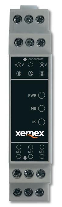
User Manual - CSMB 1.0

                                                                          DOCUMENT INFO

Version:                  1.1
Status:                   Draft
Version date:             28/05/2021
Filename:                 User manual - CSMB 1.0.docx
Number of pages:          13

                                                                        HISTORY CHANGES

  VERSION          DATE           DESCRIPTION
  1.0              19/04/21       Initial version
  1.1              21/05/21       New document layout

    28 May 2021                                   XEMEX Confidential              Page 2 of 13
User Manual - CSMB 1.0
TABLE OF CONTENTS
1 INTRODUCTION ...................................................................................................................................... 4
1.1 Scope .............................................................................................................................................................. 4
1.2 Target group ................................................................................................................................................... 4
1.3 Intended usage ............................................................................................................................................... 4
1.4 Technical assistance ....................................................................................................................................... 4
1.5 Used symbols.................................................................................................................................................. 4
1.6 Safety precautions: ......................................................................................................................................... 5
2 TECHNICAL DESCRIPTION ................................................................................................................... 6
3 TECHNICAL SPECIFICATIONS ............................................................................................................. 7
3.1 Environmental conditions .............................................................................................................................. 7
3.2 DC Power Interface......................................................................................................................................... 7
3.3 Cable Specifications ........................................................................................................................................ 7
3.4 Metering Interface ......................................................................................................................................... 7
3.5 Modbus Interface ........................................................................................................................................... 7
3.6 User Interface ................................................................................................................................................. 8
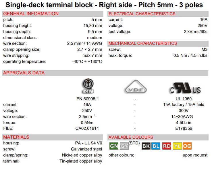
3.7 Screw terminals .............................................................................................................................................. 8
3.8 Wire stripping ................................................................................................................................................. 8
3.9 Modbus registers ............................................................................................................................................ 9
3.10 Modbus Properties ....................................................................................................................................... 10
3.10.1 Physical LAYER properties .................................................................................................................... 10
3.10.2 Data Link LAYER properties .................................................................................................................. 10
3.10.3 Application LAYER properties .............................................................................................................. 10
4 INSTALLATION INSTRUCTIONS ......................................................................................................... 11
4.1 Guidelines for safety and installation ........................................................................................................... 11
4.2 Mounting ...................................................................................................................................................... 11
4.3 Electrical wiring ............................................................................................................................................ 11
4.4 NOTES ........................................................................................................................................................... 11
5 OPERATING INSTRUCTIONS .............................................................................................................. 12
5.1 PWR - POWER Status LED – Yellow LED........................................................................................................ 12
5.2 MB – MODBUS Status LED – Red LED ........................................................................................................... 12
5.3 CS – Current Sense status LED – Green LED ................................................................................................. 12
6 CLEANING ............................................................................................................................................. 13
7 LIFTING AND CARRYING..................................................................................................................... 13
8 MAINTENANCE AND SERVICE ........................................................................................................... 13
28 May 2021 XEMEX Confidential Page 3 of 13User Manual - CSMB 1.0
1 Introduction
1.1 Scope
This manual is applicable to CSMB 1.0, a CT Current Sensor with Modbus output. It describes the specifications,
installation and operation of the product. Please read this document carefully before installation and operating.
1.2 Target group
The installation and the operation of this device and any maintenance must be carried out by a qualified person in
accordance with specific local standards and safety regulations.
1.3 Intended usage
The CSMB is only to be used for measuring electrical current and shall operate within the specified values only.
1.4 Technical assistance
In case technical assistance is needed, contact Xemex NV:
XEMEX NV
Metropoolstraat 11a
B-2900 Schoten
Belgium
Tel: +32 201 95 95
E-mail: support@xemex.eu
1.5 Used symbols
Following symbols are used in this document and/or are marked on the product:
Alternating current
Three-phase alternating current
Equipment protected throughout by DOUBLE INSULATION or REINFORCED
INSULATION
Caution, possibility of electric shock
Caution
28 May 2021 XEMEX Confidential Page 4 of 13User Manual - CSMB 1.0
1.6 Safety precautions:
DANGER — HAZARDOUS VOLTAGES
WARNING - These installation/servicing instructions are for use by qualified personnel only. To
avoid electrical shock, do not perform any servicing other than that contained in the operating
instructions unless you are qualified to do so.
Always adhere to the following checklist:
1. Only qualified personnel or licensed electricians should install the Xemex CSMB. The mains voltages of
120 Vac to 600 Vac can be lethal!
2. Follow all applicable local and national electrical and safety codes.
3. Install the meter in an electrical enclosure (panel or junction box) or in a limited access electrical room.
4. Verify that circuit voltages and currents are within the proper range for the meter model.
5. Use current transformers (CTs) with built-in TVS with a dielectric strength of at least 3.5KV 50Hz 1min and a
work voltage of 660V. Do not use current output (ratio) CTs such as 1 amp or 5 amp output CTs: they will
destroy the meter.
6. Ensure that the CTs are placed behind fuses or circuit breakers.
7. Equipment must be disconnected from the HAZARDOUS LIVE voltages before access.
8. Before applying power, check that all the wires are securely installed by tugging on each wire.
9. Do not install the CSMB where it may be exposed to temperatures below –25°C or above 75°C, excessive
moisture, dust, salt spray, or other contamination. The meter requires an environment no worse than
pollution degree 2 (normally only non-conductive pollution; occasionally, a temporary conductivity caused
by condensation must be expected).
10. Do not drill mounting holes in the device. Click the module on a DIN Rail instead.
11. If the CSMB is installed incorrectly, the safety protections may be impaired.
28 May 2021 XEMEX Confidential Page 5 of 13User Manual - CSMB 1.0
2 Technical description
The Xemex CSMB device is a Current Transformer current metering device with a Modbus Interface.
It has following interfaces:
• DC Power Interface
• RS485 Communication Interface
• User Interface
• Current Transformers (CT) Interface
DC Power
Interface
RS485 Interface
User
Interface
CT Interface
The CSMB measures the RMS current values of the three current transformer inputs over a period of 1 second.
At the end of the measurement cycle the new RMS values are stored in the corresponding Modbus registers (see
below).
This process continuously repeats every second.
28 May 2021 XEMEX Confidential Page 6 of 13User Manual - CSMB 1.0
3 Technical specifications
3.1 Environmental conditions
Protection class II
Operating temperature -25 °C - +75 °C
Storage temperature -40 °C - +85 °C
Relative humidity < 75 % year’s average at 21 °C
< 95 % less than 30 days/year, at 25 °C
Pollution Degree 2
Altitude < 2000m
Application area Residential, Indoors in suitable meter cabinet
3.2 DC Power Interface
DANGER
Use SELV power supply only!
Risk of serious injuries or death and/or at least product damage!
Connector Screw terminal connector for 0V and +12V DC
Voltage range: 12V DC, -50%, +10%
Max current consumption: 50 mA
Max cable length: 100 meter
Cable location: indoor + outdoor
Reverse polarity protection: yes
3.3 Cable Specifications
Preferably armored twisted pair with drain wire. Section 0,20 … 0,50 mm². Use wires of same pair to connect B and
A, wires from the other pair to +12V and 0V.
Example of cable type: Belden 3107A
3.4 Metering Interface
Use current transformers (CTs) with built-in TVS with a dielectric strength of at least 3.5KV 50Hz
1min and a work voltage of 660V. Do not use current output (ratio) CTs such as 1 amp or 5 amp
output CTs: they will destroy the meter.
Ensure that the CTs are placed behind fuses or circuit breakers.
Connector Screw terminal connectors for max 3 Current Transformers
Measuring principle Current measurement by Current transformer
Current range 1A ... 80A (if CT ratio = 2000)
CT ratio 2000 (default)
Input impedance 20 Ohm
Accuracy TypicallyUser Manual - CSMB 1.0
Bus termination 120 Ohm, switchable on/off
Protocol Modbus RTU over RS485
Max cable length: 100 meter
Cable location: indoor + outdoor
3.6 User Interface
Power indicator Yellow LED
Current indicator Green LED
Modbus indicator Red LED
3.7 Screw terminals
3.8 Wire stripping
28 May 2021 XEMEX Confidential Page 8 of 13User Manual - CSMB 1.0
3.9 Modbus registers
The registers below are accessible by the Modbus function code 03 – Read Holding Register.
The registers marked in blue can also be written by the Modbus function 06 – Write Single Register.
Updated settings become active after rebooting the device by writing the Reboot register.
Register
Reg length Contents Data type
address
(# of u16)
0x4000 2 Serial Number (last 8 digit of LDN) HEX
0x4002 1 Device code HEX
0x4003 1 Modbus device address UINT16
0x4004 1 RS485 baudrate low UINT16
0x4005 2 Protocol version Float ABCD
0x4007 2 Software version Float ABCD
0x4009 2 Hardware version Float ABCD
0x400B 1 Meter amps UINT16
0x400C 1 CT ratio HEX
RS485 line settings
0x400D 1 UINT16
(default 8E1)
0x400E 1 Enable / disable line termination UINT16
0x400F 1 RS485 baudrate high UINT16
0x500C 2 RMS current CT1 Float ABCD
0x500E 2 RMS current CT2 Float ABCD
0x5010 2 RMS current CT3 Float ABCD
0xFFFF 1 Reboot UINT16
28 May 2021 XEMEX Confidential Page 9 of 13User Manual - CSMB 1.0
3.10 Modbus Properties
3.10.1 Physical LAYER properties
• Baud rate:
o 1200 ... 115200
o default value is 9600 baud.
• Line setting:
o 8N1 (line settings register value = 0x04) , 8E1 (line settings register value = 0x24)
o default value is 8E1.
• Enable/disable line termination resistor:
o default value is enabled.
3.10.2 Data Link LAYER properties
• Modbus device address
o 1 .. 247
o default address is 1.
3.10.3 Application LAYER properties
Modbus RTU server which supports following Modbus Function Codes:
• Read Holding Register
• Write Single Register
28 May 2021 XEMEX Confidential Page 10 of 13User Manual - CSMB 1.0
4 Installation instructions
4.1 Guidelines for safety and installation
This installation guide must be consulted in all cases when manipulating parts which are marked
with the Caution symbol.
The installation and the operation of this device and any maintenance must be carried out by a
qualified person in accordance with specific local standards and safety regulations.
Caution: never open the secondary circuit of a Current Transformer while current is flowing
through the primary circuit!
If the secondary circuit is opened when primary current is flowing, then the voltage will go to a very
high value, possibly causing electrical arcing and/or electrical shock to service personnel. Therefore
CT’s with internal TVS must be used.
Failing to obey the ”Guidelines for safety and installation”, the guarantee no longer applies.
4.2 Mounting
Mount the device in a DIN rail cabinet.
4.3 Electrical wiring
4.4 NOTES
The Modbus Shield must only be connected at the CSMB side and not at the Modbus master side.
The Modbus Shield connection is also connected to the protected earth of the building.
28 May 2021 XEMEX Confidential Page 11 of 13User Manual - CSMB 1.0
5 Operating instructions
After installation and applying DC power the device starts automatically measuring the RMS current values flowing
through the connected current transformers.
A connected Modbus master can request these values by reading the corresponding Modbus registers.
The CSMB device gives visual feedback by its 3 Status Indicators:
5.1 PWR - POWER Status LED – Yellow LED
• Not lit: CSMB device is not powered
• Blinking: CSMB device is powered, but voltage is below 6 Volt
• Lit: CSMB device is powered, voltage is above 6 Volt
5.2 MB – MODBUS Status LED – Red LED
• Blinks with a period of 1 second, its duty cycle indicates the current level.
5.3 CS – Current Sense status LED – Green LED
• Not lit no data received within the last 10 seconds.
• Blinking data received, but no valid* modbus request received within the last 10 seconds.
• Continuously lit valid* modbus request received within the last 10 seconds.
Valid* = CRC verified frame for own address
28 May 2021 XEMEX Confidential Page 12 of 13User Manual - CSMB 1.0
6 Cleaning
Clean the unit with a slightly damp cloth and mild detergent.
7 Lifting and carrying
Use care when lifting and carrying the product.
8 Maintenance and Service
There are no serviceable parts inside.
End Of Document.
28 May 2021 XEMEX Confidential Page 13 of 13You can also read