ORDU BLUE PAPER OMX 2021 - Orbea
←
→
Page content transcription
If your browser does not render page correctly, please read the page content below

TECHNICAL MANUAL   EN | ES

BLUE PAPER
 ORDU
  OMX 2021

2 | ORBEA                                             TECHNICAL MANUAL   BLUE PAPER ORDU · O MX 2021                    ORBEA | 3
                                                                                                                              EN

INDEX                                       EN P.02 | ES P.56

01 IN T R ODU CTI ON                                       04            CHAINSTAYS AND BOTTOM BRACKET
                                                                         SEATPOST
Key to symbols
                                                                         HANDLEBAR
02 ORBEA WARRANTY                                           06            Base handlebar
                                                                          Bridge and extensions
03 M AINTENANC E                                            08           AERO BOTTLE AND TOOLBOX
Keep your bicycle clean
Keep your drivetrain lubricated                                          0 8 CABLE ROUTING                                   35
Inspect your bicycle before every ride                                   CABLE ROUTING. MECHANICAL ASSEMBLIES
Maintenance schedule                                                      Brake hoses
Replacement parts                                                         Gears
After a crash or an impact                                               CABLE ROUTING. ELECTRONIC ASSEMBLIES
                                                                          Brake hoses
04 US E WARNI NGS                                            11           Shimano DI2 system
Maximum tyre width                                                        Blipbox junction (Sram Etap)
Seatpost and front post minimum insertion
Intended use                                                             0 9 A DJ UST M E NT O F F ITTIN G ELEM EN TS        42
                                                                         Front post height adjustment
OR D U OMX 2021                                             12           Extensions position adjustment
05 GEOMETRY AND SIZING                                      14           Saddle position and angle adjustment
                                                                         Bridge and extensions angle adjustment
06 TECHNICAL SPECIFICATIONS                                 16           Bridge orientation adjustment
07 ASSEMBLY AND SPARES                                      19           Base handlebar height change

HEADSET AND STEM                                                         10 DECLARATION OF CONFORMITY                        54
 Head tube measurements
 *GCFUGVURGEKƂECVKQPU                                                   11 ADDITIONAL INFORMATION                          55
 Headset and stem assembly and spares                                    ORDU OMX DEALER ASSEMBLY GUIDE (ES|EN|FR|DE)       110
 Headset adjustment
AXLES AND REAR DERAILLEUR HANGER
 Trainer compatibility
 Speed release axles use
4 | ORBEA TECHNICAL MANUAL BLUE PAPER ORDU · O MX 2021 ORBEA | 5
EN
01 INTRODUCTION
KEY TO SYMBOLS
This technical manual contains important information about your bicycle, its Throughout this technical manual, various symbols are used that indicate
use, maintenance and replacement parts. Please read it carefully. instructions and warnings for use, maintenance and assembly. Pay attention
to these symbols to avoid hazardous situations and ensure the correct use and
This document is a supplement to the General User’s Manual for Orbea bicycles assembly of all components.
and components, which describes in a more detailed manner their appropriate
use and the adjustment of the general components of the bicycles for safe The meaning of these symbols is explained below. In this manual, the symbol
riding and operation. You can see and download the User’s Manual and the rest may appear accompanied only by the relevant instruction for the component
of the technical manuals for Orbea products from our website: described. Read the following information carefully in order to understand their
meanings.
www.orbea.com/us-en/soporte/manuales
You can consult the information on the use, maintenance and characteristics SAFETY INSTRUCTIONS TOOLS AND TIGHTENING TORQUES
of the components of other manufacturers that are assembled on our bicycles,
such as wheels, handlebars, pedaling assistance systems, suspension forks, DANGER: Immediately hazardous situation. SPANNER TORX KEY
etc, on the manufacturer’s website or through their dealer in your country. If not avoided, serious injury or even death
will occur.
ALLEN KEY PHILLIPS
SCREWDRIVER
WARNING: Potentially hazardous situation.
If not avoided, serious injury or even death The key number is indicated
may occur.
6 inside the symbol. 6
10 N.m
CAUTION: Potentially hazardous situation. TIGHTENING TORQUES: The corresponding tightening
If notavoided, minor or moderate injury torque (in Newtons/meter) is indicated beneath the sym-
may occur. bol of the tool to use for the element described.
ASSEMBLY COMPOUNDS
Not related to injury. Property situation
hazard. OIL: Light lubrication of elements like chains
and cables.
GREASE GREASE: High quality assembly grease to
avoid creaking and seizing.
The symbols DANGER and WARNING inform about a dan-
gerous situation that, if not avoided, may cause an acci- CARBON PASTE: %CTDQPƂDGTCUUGODN[
dent. An accident while riding a bicycle always poses risk FIBER CARBON GRIP
compound to increase friction between
of serious injury or even death. In this manual, the risk of ECTDQPƂDGTEQORQPGPVU
death may therefore not always be mentioned when these
symbols appear, since the risk is explained here. LOCTITE SERIES 600: Fixing cylindrical
surfaces.
LOCTITE SERIES 200: Threadlock. Medium
resistance.
LOCTITE SERIES 400: Instant adhesive.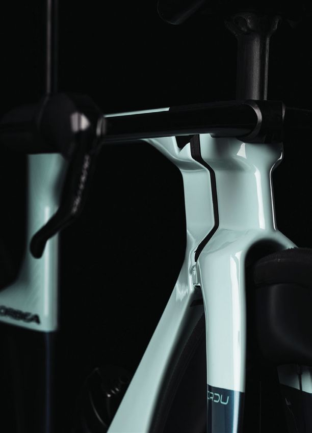
6 | ORBEA                                                                                                  TECHNICAL MANUAL       BLUE PAPER ORDU · O MX 2021                                                         ORBEA | 7
                                                                                                                                                                                                                             EN

02 ORBEA WARRANTY

Our continuous daily effort to provide maximum quality
of our bicycles allows us to offer the following warranty
                                                               This warranty extends the original period of coverage
                                                               against paint, varnish or corrosion defects on the frames
                                                                                                                                  02. REGISTER YOUR BARCODE
                                                                                                                                                                    WARRANTY C LAIM PROC ESS
and coverage conditions:                                       and rigid forks for one additional year after the end of the
                                                                                                                                                                    All warranty claims must be processed through an author-
                                                               legal warranty period.
                                                                                                                                                                    ized Orbea dealer, who will perform the initial diagnosis
LEGAL WARRANTY                                                 Orbea’s lifetime commercial warranty only covers frames
                                                                                                                                                                    and send Orbea all the necessary documentation for a
                                                                                                                                                                    complete diagnosis of the claim in question. The dealer
                                                               and rigid forks, but not OC components.
Orbea offers the original owner of the Orbea bicycle, rigid                                                                                                         will inform the owner about the status of the process and
fork or original component a legal warranty of 2 years from                                                                                                         the decision made on the warranty claim by Orbea.
                                                               For a full description of the warranty conditions for the
the date of purchase of the items, or the period stipulated    lifetime warranty, please visit:
as the legal warranty in the country of purchase.                                                                                                                   We recommend that you always visit the dealer where you
                                                                                                                                                                    purchased your bicycle to process a warranty claim, or the
                                                               www.orbea.com/us-en/garantia#garantia-deporvida-orbea
This warranty covers all Orbea products against manufac-                                                                                                            dealer you chose during the process of purchasing a bicy-
turing defects and/or lack of compliance and guarantees                                                                                                             cle that was delivered directly to your home. If you cannot
the repair or replacement of the defective product at no       R E GI ST E R YOU R BICYCLE                                                                          visit the original dealer, you can check the list of author-
                                                                                                                                                                    ized dealers on our website or contact Orbea directly so
cost to the affected customer. Likewise, this warranty also
covers paint, varnish and corrosion defects on all frames      +P QTFGT VQ DGPGƂV HTQO VJG 1TDGC NKHGVKOG YCTTCPV[ GZ-   03. WHERE TO FIND YOUR BARCODEA   we can indicate the dealer you should visit.
and rigid forks assembled on our bicycles during the pe-       tension, you must register your bicycle within 30 days of
TKQFURGEKƂGFKPVJGRTGXKQWURCTCITCRJQHVJKUYCTTCPV[      its purchase at:                                                                                     www.orbea.com/es-es/distribuidores/?country

This warranty does not cover in any case damage derived        www.orbea.com/es-es/acceso-registro?from=register-plate/                                             www.orbea.com/us-en/contacto
from inappropriate use, falls or accidents or the lack of
maintenance, as well as the normal wear and tear of con-       01. REGISTER YOUR ACCOUNT
sumable parts, such as, by way of example, but without
limitation: seals, bearings, handlebar tape, spokes, tires,
saddles, etc.

For a full description of the coverage conditions and the
legal warranty, please visit:

www.orbea.com/us-en/garantia

ORBEA LIFETIME WARRANTY
As a supplement to the legal warranty, Orbea offers the
original buyer of the bicycle the Orbea lifetime commer-
cial warranty, as long as they have registered their product
on the Orbea website within 30 days of its purchase. This
lifetime warranty covers the frames and rigid forks that we
mount on our bicycles against manufacturing defects and
material conformity issues with no time limitation.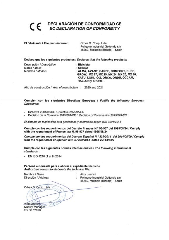
8 | ORBEA TECHNICAL MANUAL BLUE PAPER ORDU · O MX 2021 ORBEA | 9
EN
03 MAINTENANCE
Orbea products are carefully designed to be long-lasting, INSPECT YOUR BICYCLE BEFORE EVERY RIDE BEARINGS: The bearings (bottom bracket, linkage pivot For components from other brands mount-
GHƂEKGPVCPFGCU[VQOCKPVCKP6JGECTDQPCPFCNWOKPWO points, headset, wheels, etc.) are elements subject to wear ed on Orbea bicycles, you can check the
frames and forks are extremely corrosion-resistant. Do a quick check before each ride to make sure that your that must be inspected on a regular basis to ensure that recommended or mandatory maintenance
bicycle is in optimal operating conditions. You might dis- they operate correctly. Bearings in poor condition can periods on the manufacturer’s website or
However, your bicycle needs regular maintenance of its cover small problems that could turn into major issues damage the components in which they are installed. Ad- by contacting the distributor of that brand
components in order to ensure that it works properly and during the ride. verse weather conditions speed up bearing wear. Bearings in your country.
safely, and to ensure its longevity. that have excessive play or that do not turn smoothly must
FRAME: Inspect the frame and the fork, looking for cracks be replaced immediately. In the case of any doubt, consult Damage to components as a result of failing
KEEP YOUR BICYCLE CLEAN or other damage. No strange noises should be heard. In your authorized dealer. to follow the recommended maintenance
the event of any damage to the frame, avoid using the periods could result in damage that is not
Clean your bicycle with mild soap and water on a regular bicycle and contact your authorized dealer for inspection. Damage to components like the frame, bi- covered by the warranty conditions of Orbea
basis to keep it working like new, and check the condition cycle wheels, etc. associated with the lack or the component manufacturer.
of the frame and its components. Do not use pressurized CHAIN: Ensure it’s clean and lubricated. The drivetrain of maintenance and the replacement of the
water, since it could damage components like bearings or should not make any abnormal noises. bearings are not covered by the warranty The failure to comply with maintenance
the tubes of the frame. conditions. periods could result in damage to the
BRAKES: Check that the brakes operate properly and components and lead to malfunctions and
Citrus-based degreasers are biodegradable and very effec- in a safe manner. Check the tightening torques of the Failure to follow the recommendations out- accidents.
tive in removing grease from drivetrain components and components. lined in this manual and riding a bicycle that
the chain. shows signs of the symptoms described above HEADSET:
TIRES: Check for worn tires and look for cuts on the tread may cause accidents and serious injuries. · Inspection of its operation before each ride.
Accumulated dirt can complicate the visual or sides. If you spot damage, replace the tire. Make sure · Disassembly and manual inspection of the bearings once
inspection of the components and hide dam- that the tire pressure is adequate. TIGHTENING TORQUES. Always check the every 6 months of use.
age that could potentially cause malfunctions tightening torques and install the compo-
BOTTOM BRACKET:
or accidents. WHEELS: Check that the wheels turn smoothly and show nents described in this manual according
· Inspection of its operation before each ride.
no signs of lateral deviations. Turn the wheel slightly from VQVJGVKIJVGPKPIVQTSWGURGEKƂECVKQPU(QN-
· Disassembly and manual inspection of the bearings once
Built-up dirt causes the premature wear side to side to check that there is no lateral play in the NQYVJGVKIJVGPKPIVQTSWGURGEKƂECVKQPUHQT
every 6 months of use.
of components and can even damage the bearings. Make sure that there are no broken or loose components from other manufacturers in-
bicycle frame in areas such as the bearing spokes. Check that the axles or quick-release levers are stalled on your Orbea bicycle. The failure to DRIVETRAIN:
housings and moving parts. Damage due to securely tightened with the correct tightening torque. HQNNQYVJGUGURGEKƂECVKQPUOC[NGCFVQVJG · Inspection of its operation before each ride.
the lack of cleaning and maintenance is not malfunction of the components, accidents · Regular inspection of chain wear every 500 km. A chain
covered by the warranty. HEADSET: Activate the front brake and move the front part and even death. that is worn beyond the manufacturer’s recommenda-
of the bicycle back and forth, applying pressure on the tions must be replaced to prevent damage to the rest
of the drivetrain components. The failure to observe the
MA IN TEN A N CE SC H EDULE
KEEP YOUR DRIVETRAIN LUBRICATED handlebars with the rear wheel on the ground. Check for
strange noises or movement of the headset, which could manufacturer’s recommendations in terms of wear could
Once you have cleaned your bicycle, lubricate the driv- indicate that the bearings are worn or the headset has not necessitate the replacement of the rest of the parts of
GVTCKP URGEKƂECNN[ VJG EJCKP 7UG VJG OKPKOWO COQWPV been correctly tightened. Once the headset is correctly the drivetrain.
necessary to lubricate the links, removing any excess adjusted, check that it turns smoothly. Maintenance periods for the components
WHEELS:
amounts to prevent them from attracting dirt, causing the indicated below are general guidelines and
· Inspection of its operation before each ride.
drivetrain to not work properly and the premature wear of LINKAGE PIVOT POINTS: On full suspension bicycles, largely depend on factors such as weather
· Disassembly and manual inspection of the bearings and
the components. check that all the linkage pivot points rotate smoothly and conditions in which your bicycle is ridden
all components once every 6 months.
show no signs of play in the bearings. Pull the linkages (adverse conditions considerably reduce the
Avoid the use of aerosol lubricants to pre- from side to side on the bicycle and pay attention to any life of the components and increase mainte- SHOCKS AND SUSPENSION FORKS:
vent them from adhering to the brake sur- noise or play at the pivot points. If the linkages do not nance frequency), the cleanliness of your bi- · Inspection of its operation before each ride.
faces. Always check the brakes after lubri- operate smoothly or show signs of play, it could be a sign cycle and its components (components with · Inspection and full maintenance every 125 hours or once
cating the drivetrain. that the tightening torques are incorrect or that the bear- accumulated dirt wear more quickly), and C [GCT YJKEJGXGT QEEWTU ƂTUV D[ VJG OCPWHCEVWTGToU
ings are worn or damaged. use (more demanding use of the bicycle will authorized dealer.
require more frequent maintenance periods).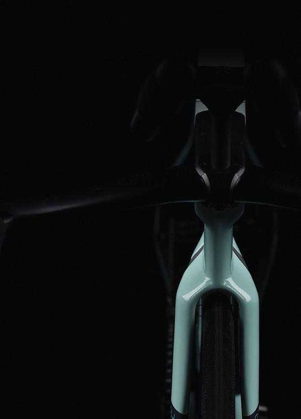
10 | ORBEA TECHNICAL MANUAL BLUE PAPER ORDU · O MX 2021 ORBEA | 11
EN
04 WARNINGS
OF USE
TELESCOPIC SEAT POSTS:
· Inspection of its operation before each ride.
R E P LAC EMEN T PA RTS The materials used on carbon frames and M AXIM UM TYRE W IDTH
· Inspection and full maintenance every 125 hours or once forks are rigid and strong, but if overloaded
Always use original Orbea replacement parts or those from QTKHVJG[UWHHGTCPKORCEVVJGƂDGTUFQPQV 6JKUVGEJPKECNOCPWCNURGEKƂGUVJGOCZKOWOUK\GQHVJG
C [GCT YJKEJGXGT QEEWTU ƂTUV D[ VJG OCPWHCEVWTGToU
the component manufacturer in question. bend, and they will break. A strong enough tyres that can be mounted on the frame. Always follow
authorized dealer.
impact to this material could cause damage these guidelines when installing tyres on your bicycle.
PIVOT POINTS ON FULL SUSPENSION FRAMES: The use of non-original replacement parts may VJCV YJKNG PQV XKUKDNG CV ƂTUV INCPEG EQWNF
· Inspection of its operation before each ride. cause damage that results in malfunctions cause the materials to fail in the future. In the However, the real measurements of the tyre circumfer-
· Disassembly of the frame and the manual inspection of and accidents with serious consequences. case of any doubt about the consequences of ence and width may change from one manufacturer to
all the bearings every 125 hours of use or once a year a fall or accident, contact your Orbea dealer another. When installing a tyre other than that originally
YJKEJGXGTQEEWTUƂTUV 6JGUGVKOGUOC[DGUJQTVGTFG- The installation of some of the replacement for a correct diagnosis of the materials. mounted on your Orbea bicycle, check that there is at
pending on the conditions in which the bicycle is ridden. parts in this technical manual are beyond least 3 mm between the top and the sides of the tyre and
More demanding use of the bicycle or use in adverse the mechanical knowledge of most bicycle Check the drivetrain and the wheels to make sure that the any part of the frame.
weather conditions or in mud requires the disassembly WUGTU+H[QWCTGPQVSWCNKƂGFVQKPUVCNNVJGUG components operate correctly. If you discover any damage
and inspection of the frame once every 75 hours of use replacement parts, always visit an Orbea to the components, stop using the bicycle immediately. Damage to the frame or components due
QTQPEGGXGT[OQPVJU YJKEJGXGTEQOGUƂTUV +HCDGCT- dealer for maintenance on your bicycle and to the use of a tyre that does not comply with
ing does not turn smoothly or has excessive play, it must its components. The failure to properly install Even if you do not observe any damage, pay close atten- these measurements is not covered by the
be replaced immediately. replacement parts can result in malfunctions, tion to the sound of your bicycle when you ride it again. warranty conditions.
accidents and serious injuries. Damage and other problems can cause unusual noises.
GEAR CABLES AND HOUSING:
· Inspection of its operation before each ride.
The installation of non-original replacement
If you notice any unusual noise, stop using your bicycle
immediately and contact your Orbea dealer for a correct
MINIMUM SEATPOST
· Replacement of gear cables every 6 months to 1 year
depending on the conditions in which the bicycle is used.
parts can damage your bicycle and is not diagnosis of the problem. AND FRONT POST INSERTION
covered by the warranty conditions.
BRAKES: #NYC[U HQNNQY VJG URGEKƂECVKQPU TGICTFKPI
· Inspection of the operation and wear of the brake pads or
shoes before each ride. AFTER A CRASH OR AN IMPACT TAKE YOUR ORBEA BICYCLE TO AN AUTHORIZED the minimum insertion depth of the seatpost
or the frame on road bicycles with exclusi-
DEALER FOR A PROFESSIONAL INSPECTION
· Check the wear on disc brakes and the cables or hydrau- ve Orbea seatposts.On Ordu, also observe
lic lines every 6 months to 1 year depending on the con- Falling off your bike is part of cycling. If you have an acci-
dent on your Orbea bicycle, be sure that you’re okay and Some of the consequences of a fall or accident can only be the instructions for the minimum front post
ditions in which the bicycle is used. Flush the hydraulic detected by completely disassembling the bicycle to check insertion. The failure to follow these instruc-
lines once a year. seek medical care, if necessary. If you are uninjured, you
should check the condition of your bicycle before conti- for the presence of damage or other signs of deterioration. tions can cause stresses on the materials
nuing to ride. beyond the conditions for which they were
Some of these checks and maintenance A collision or impact can cause serious da- designed and cause damage not covered by
needs go beyond the mechanical knowledge mage to your bicycle and its components, the warranty conditions, as well as accidents
of most bicycle users. If you are not quali- INSPECT THE FRAME AND THE BICYCLE COMPO-
NENTS TO SEE IF THEY HAVE BEEN DAMAGED IN causing them to malfunction or wear out that can result in serious injuries.
ƂGFVQRGTHQTOVJGPGEGUUCT[OCKPVGPCPEG prematurely. Malfunctions can occur sud-
ANY WAY
always visit an Orbea dealer for maintenance
on your bicycle and its components. The
denly and without notice, causing you to lose
control of your bicycle and suffer serious in-
INTENDED USE
failure to perform proper maintenance can If you detect any problem, do not continue to ride the
bicycle. juries, or even death. The intended use of all models is
result in malfunctions and accidents with se-
rious consequences. ASTM Condition 1, for use on a
POINTS TO CHECK regular paved surface where the
Maintenance performed incorrectly can dam- tyres are intended to mantain
age the components, which are not covered Inspect the frame and the fork to identify whether either of ground contact.
by the warranty conditions. these components have been broken or bent. If you detect
any damage or cracks, you must stop using the bicycle im- For information about all ASTM
mediately. On carbon frames, look for cracks or soft spots categories, consult the General
in the carbon. If you detect any of these symptoms, you User Manual.
must stop using the bicycle immediately.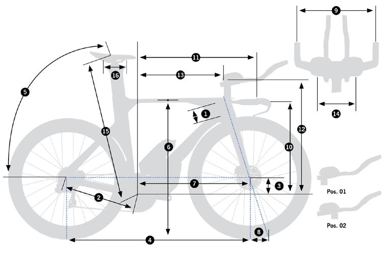
12 | ORBEA   TECHNICAL MANUAL   BLUE PAPER ORDU · O MX 2021          ORBEA | 13
                                                                            EN

                                                              ORDU
                                                               OMX 2021
14 | ORBEA               TECHNICAL MANUAL   BLUE PAPER ORDU · O MX 2021                                                                             ORBEA | 15
                                                                                                                                                             EN

05 GEOMETRY AND SIZING                      SI ZE S                                                          XS         SM            ML             XL
       ORDU OMX                               1.- Head Tube Length                                            59         96            96            149
                                              2.- Chainstay Length (Actual)                                  405        405           405           405
                                              3.- BB Drop                                                     75         75            75            75
                                              4.- Wheel Base                                                 971        1007          1007          1048
                                              5.- Seat Angle (Virtual)                                      74-78º     74-78º        74-78º        74-78º
                                              6.- Standover Height                                           746        781           781            831
                                              7.- BB-Front Wheel Axle                                        578        613           613           654
                                              8.- Trail                                                       60         60            60            60
                                              9.- Width                                                      380        380           380           380
                                            10.- Stack
                                                 High Position                                               481        516           516           566
                                                 Low Position                                                451        486           486           536
                                            11.- Reach                                                       641        665           665           689
                                            12.- Stack MAX                                                   605        640           690            740
                                                 Frontpost Insertion MIN                                      40         40            40            40
                                                 Stack MIN (w/o FP TRIMMING)                                 588        595           645           696
                                                 Stack MIN (w/ FP TRIMMING)                                  515        550           550           600
                                            13.- Reach
                                                 MAX (Bridge Pos. 1)                                         481        505           505           529
                                                 MIN (Bridge Pos. 2)                                         361        385           385           409
                                            14.- Elbow rests min/max Width (c-c)                            105-195   105-195       105-195        105-195
                                                 Tilt                                                        0-15º     0-15º          0-15º         0-15º
                                            15.- Height MAX                                                  762        797           827            876
                                                 Seatpost Insertion MIN                                      100        100           110            110
                                                 Height MIN (RECOMMENDED)                                      -        724           754            775
                                                 Height MIN (w/o SP TRIMMING)                                683        674           714            764
                                                 Height MIN (w/ SP TRIMMING)                                 589        624           624            675
                                            16.- Setback Travel                                              100        100           100            100

                                                        HE I GHT (CM)                     HEIG HT (IN)                                S IZE*
                                                               185                             72.8”                                    XL

                                            * These sizing measurements are an approximate guide. The most effective method to choose the right size for
                                            you is to try the bicycle at one of our authorized dealers.
16 | ORBEA TECHNICAL MANUAL BLUE PAPER ORDU · O MX 2021 ORBEA | 17
EN
05 TECHNICAL
SPECIFICATIONS
Material Rear axle measurements 12x165mm
Frame ORBEA CARBON OMX Rear axle thread pitch DOUBLE LEAD “MAVIC SPEED RELEASE” 2P1.0
Fork ORBEA CARBON OMX Rear axle thread length 15mm
Seatpost / frontpost ORBEA CARBON OMX CARBON AERO. ORDU SPECIFIC
Seatpost XS-S/M: 330mm
Recommended use TRIATHLON/TT
M/L-XL: 370mm
XS - S/M - M/L - XL
Available sizes Seatpost wedge INTEGRATED. ORDU SPECIFIC
(S/M and M/L sizes share frame and fork. Seatpost and frontpost length changes)
XS: 100mm
Base handlebar AERO. ORDU SPECIFIC. 2 POSITIONS S/M: 100mm
Seatpost minimum insertion
(TQPVRQUV DTKFIG1TFWURGEKƂE M/L: 110mm
#GTQ1TFWURGEKƂE2QUKVKQPU
Adjustable in height, length and angle XL: 110mm
Compatible extensions diameter 22.2mm Front post minimum insertion 40mm. All sizes
Front post adjustment range SEE SIZING SECTION Front derailleur DOWNPULL. BRAZE-ON. REMOVABLE HANGER
ORDU SPECIFIC Front derailleur angle 63º
Fork Integrated headtube MINIMUM 40T - MAXIMUM 56T
Hinge type headset Chainring size (1X)
MAXIMUM OVAL 56T
Fork rake 53mm
SHIMANO/CAMPAGNOLO: MIN 50T - MAX 56T
XS Big chainring SRAM: MIN 46T - MAX 56T
Fork sizes
S/M-M/L MAXIMUM BIG OVAL CHAINRING: 56T
5K\GURGEKƂEKPVGITCVGFJGCFVWDG Chainring size (2X)
XL
MAXIMUM 46T
Headset 1" - 1-1/8" INTEGRATED. HINGE TYPE Small chainring
MAXIMUM SMALL OVAL CHAINRING: 46T
Headset UPPER: 1"
Cassette smallest sprocket size FROM 10T TO 14T
bearings LOWER: 1-1/8"
Minimum Q-factor 146mm
Wheel size
Maximum crank length 175mm
Maximum tyre width 700C. 28”
Rear derailleur hanger STANDARD AND DIRECT MOUNT
UCI legal 700x28C (External diameter: 688mm)
SHIMANO: ROAD 2x11 (Goupsets with TT brake and gear levers)
Triathlon 700x30C (External diameter: 692mm)
SRAM: ROAD 2x11, 2x12, 1x12 (Goupsets with TT brake and gear levers)
Optimal aerodynamics 700x25C
Blipbox juntion bracket (Etap) bolted to stem cover
Bottom bracket PRESS FIT. BB386EVO Drivetrain compatibility
(Only disc brake groupsets) CAMPAGNOLO: Campagnolo TT disc brake levers not available
Bottom bracket shell width 86.5mm
Bottom bracket shell diameter 46mm TRP HD-T912 (brake only): It may be necessary to shorten the base handlebar
ends until the desired lever position is achieved
Front dropouts standard 12x100mm
Front axle measurements 12x119mm
Front axle thread pitch DOUBLE LEAD “MAVIC SPEED RELEASE” 2P1.0
Front axle thread length 13mm
Rear dropouts standard 12x142mm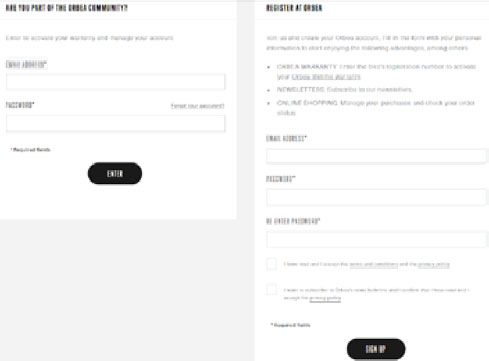
18 | ORBEA TECHNICAL MANUAL BLUE PAPER ORDU · O MX 2021 ORBEA | 19
EN
07 ASSEMBLY AND SPARES
HEADSET AND STEM
DI2 YES SEATPOST INTERNAL BATTERY ONLY
Di2 and EPS compatibility EPS YES. (V3 AND V4 INTERNAL BATTERY) HEADTUBE MEASUREMENTS
TT DISC BRAKE LEVERS NOT AVAILABLE
INTERNAL (BRAKES AND GEARS) Ø 46.2
Through handlebar, extensions, bridge, frontpost, stem, headset and frame
4.7
Cable routing Ø 38.2
Full sleeve
Internal front brake routing through fork blade
Front brake DISC ONLY. FLAT MOUNT*
45º
Front rotor diameter MIN 140mm / MAX160mm (with adapter)
Rear brake DISC ONLY. FLAT MOUNT*
Rear rotor diameter MIN 140mm / MAX160mm
4GCTECNKRGTƃCVOQWPVƂZKPIDQNVNGPIVJ Shimano = 33mm
(Chainstay height = 20mm) Sram = 27mm
1. AERO HOLDER AND BOTTLE (500ml) ORDU SPECIFIC
Bottle holder
Standard holder and bottle compatible
TOOLBOX IN DOWNTUBE
Storage
Capacity for: 1 inner tube, 2 CO2 cartridges and CO2 adapter
6.8
AFTERMARKET OPTIONS. BETWEEN EXTENSIONS
Hydration systems compatibility
AND SADDLE RAILS***
Food storage compatibility AFTERMARKET OPTIONS. BETWEEN EXTENSIONS***
Mudguards compatible NO
Rack compatible NO Ø 41.2
Kickstand compatible NO Ø 46.2
Childseat compatible NO
Trailer compatible NO
SRM: YES HEADSET SPECIFICATIONS
POWER2MAX: YES
STAGES: YES Compression ring/
Powermeter compatibility** ROTOR POWER: YES Hinge type Bearing FSA Bearing
TYPE ID* OD** crown race
POWERBOX: YES headset angle CODE dimensions
contact angle
QUARQ: YES
SHIMANO: YES
Integrated Angular contact bearing
UCI legal YES TOP 38.2mm 46.2mm 45º 36º TH-373
1” 38x27.2x6.5mm
Integrated Angular contact bearing
BOTTOM 41.2mm 46.2mm 45º 36º TH-873E
1-1/8” 41x30.2x6.5mm
* Not all calipers and rotors in the market are compatible with all frames.
#NNEQORQPGVUURGEKƂECVGFHTQO1TDGCJCXGDGGPVGUVGF(QTCHVGTOCTMGVQRVKQPUEJGEMEQORQPGPVGUFKOGPUKQPUCPFVQNGTCPEGU
befores purchasing.
** For other powermeters, consult the compatibility and dimensions with the manufacturer. * ID: Internal headtube diameter.
*** Consult the food and hydration systems characteristics with the manufacturer for their compatibility with Ordu OMX. ** OD: External headtube diameter.20 | ORBEA TECHNICAL MANUAL BLUE PAPER ORDU · O MX 2021 ORBEA | 21
EN
HEADSET AND STEM 01 ORDU HEADSET BEARINGS KIT The headset axle and steering limiter block are
ASSEMBLY AND SPARES ART Nº: X1720000 QTY. UK\G URGEKƂE 4GCF VJG CTVKENG FGUETKRVKQP VQ
1.1 UPPER BEARING 1" INTERN. CABLING 1 order the correct component for your frame.
1.2 LOWER BEARING 1-1/8" 1
3
5.3/6.2 3 GREASE
2 N.m 02 HINGE HEADSET AXLE KIT ORDU XS 0 2 HINGE HEADSET AXLE KIT ORDU S/M-M/L
GREASE
2.1/6.1 4 N.m (TCOGUK\GURGEKƂE (TCOGUK\GURGEKƂE
ART Nº: X1730300 QTY. ART Nº: X1730500 QTY.
2.1 HEADSET PRELOAD BOLT M6x30 2.1 HEADSET PRELOAD BOLT M6x30
1 1
COUNTERSUNK COUNTERSUNK
2.2 HINGE HEADSET AXLE 61mm 1 2.2 HINGE HEADSET AXLE 61mm 1
5.1
GREASE 4 5.2
6 N.m 02 HINGE HEADSET AXLE KIT ORDU XL 0 3 ST EERING L IM IT ER BLOCK ORDU XS
(TCOGUK\GURGEKƂE (TCOGUK\GURGEKƂE
ART Nº: X1730900 QTY. ART Nº: X1740300 QTY.
2.1 HEADSET PRELOAD BOLT M6x30 3.1 STEERING LIMITER BLOCK ORDU XS 1
1
COUNTERSUNK
3.2 BOLT M4x12 COUNTERSUNK 1
4 2.2 HINGE HEADSET AXLE 98mm 1
GREASE 1.1
03 STE E R IN G LIMITER BLOCK ORDU S /M -M /L 0 3 ST EERING L IM IT ER BLOCK ORDU XL
(TCOGUK\GURGEKƂE (TCOGUK\GURGEKƂE
GREASE 1.2 ART Nº: X1740500 QTY. ART Nº: X1740900 QTY.
3.1 STEERING LIMITER BLOCK ORDU S/M-M/L 1 3.1 STEERING LIMITER BLOCK ORDU XL 1
3.2 BOLT M4x12 COUNTERSUNK 1 3.2 BOLT M4x12 COUNTERSUNK 1
04 HEADSET PRELOAD RING ORDU. INT. CABLING 0 5 ORDU OM X ST EM
GREASE
3 3.2 ART Nº: X1750000 QTY. ART Nº: X1760000 QTY.
HEADSET PRELOAD RING ORDU. INT. 5.1 ORDU OMX STEM 1
4 N.m CABLING
1
5.2 BOLT M5x15 2
3.1 5.3 BOLT M5x30 COUNTERSUNK 2
6
06 H AN DLE BAR / STEM BOLT KIT ORDU OM X
GREASE 2.2
6 ART Nº: X1770000 QTY.
6.1 H/SET PRELOAD BOLT M6x30
1
Always follow the recommended 6 N.m COUNTERSUNK
torque settings. 6.2 BOLT M5X30 COUNTERSUNK 4
6.3 HANDLEBAR M6 BOLT. W/ INTERNAL
2
THREAD
6.4 BRIDGE FIXING BOLT M6x35 2
6.5 BOLT M2.5x10 STEM COVER 422 | ORBEA TECHNICAL MANUAL BLUE PAPER ORDU · O MX 2021 ORBEA | 23
EN
HEADSET ADJUSTMENT
1.5
1
0.5 N.m
5
3 2 1 3
2 N.m 4 N.m 3
2
4
4 3
6 N.m
Always follow the recommended Always follow the recommended
torque settings. torque settings.
HEADSET ADJUSTMENT. REGULAR HEADSET ADJUSTMENT
AFTER FORK ASSEMBLY
1. Remove the stem cover to access the headset adjust-
(KZVJGUVGOVQVJGHQTMYKVJVJGƂZKPIDQNVUVQUVQRVJG ment bolts.
stem from turning when adjusting the headset.
.QQUGPVJGUVGOƂZKPIDQNVUVQVJGEQORTGUUKQPTKPI
2. Adjust the headset preload bolt until there is no play in
the headset and it turns smoothly. 3. Adjust the headset preload bolt until there is not play in
the headset and it turns smoothly.
3. Fix the stem to the preload ring.
6KIJVGPVJGUVGOƂZKPIDQNVUVQVJGRTGNQCFTKPI
5. Install the stem bover.24 | ORBEA TECHNICAL MANUAL BLUE PAPER ORDU · O MX 2021 ORBEA | 25
EN
AXLES AND REAR DERAILLEUR Ordu OMX is only compatible with Mavic
Speed Release standard thru-axles with a
0 7 THRU-AXLE ROAD 12x165mm LITE DOUBLE LEAD
THREAD PITCH 2P1.0x15mm
double-lead 2P1.0 thread pitch for faster ART Nº: X0510000 QTY.
wheel changes. The use of axles with other 7.1 AXLE ROAD 12x165x2P1.0x15mm LITE 1
thread pitch will damage the frame. 7.2 AXLE WASHER 12mm 1
REAR AXLE
7 07 A MAVIC SPEED RELEASE AXLE 12x142mm 0 8 REAR DERAILLEUR HANGER STANDARD ROAD 20 X12
6
ART Nº: X0520000 QTY. ART Nº: X0470000 QTY.
10 N.m MAVIC SPEED RELEASE AXLE 12x142mm 1 8.1 DER. HANGER ROAD 20 STD X12
8.2 BOLT M4x12
1
1
The bolt is not used on Ordu OMX
7A
09 REAR DERAILLEUR HANGER DIRECT MOUNT ROAD 20 X12 1 0 M18 DER. HANGER NUT X12 ROAD 20
10 N.m
ART Nº: X0480000 QTY. ART Nº: X0490000 QTY.
9.1 DER. HANGER ROAD 20 DM X12 1 M18 DER. HANGER NUT X12 ROAD 20 1
9.2 BOLT M4x12
1
The bolt is not used on Ordu OMX
GREASE
10 17 11 THRU-AXLE ROAD 12X119mm LITE DOUBLE LEAD 1 1 A MAVIC SPEED RELEASE AXLE 12x100mm
THREAD 2P1.0x13mm
8 N.m
ART Nº: X0540000 QTY. ART Nº: X0550000 QTY.
11.1 AXLE ROAD 12x119x2P1.0x13mm LITE 1 MAVIC SPEED RELEASE AXLE 12x100mm 1
Always follow the recommended
torque settings. 11.2 AXLE WASHER 12mm 1
8
6
9
TRAINER AXLES
FRONT AXLE COMPATIBILITY 10 N.m GREASE
12.1
6
To use your Ordu OMX on a trainer, a double- 17
lead 2Px1.0 thread pitch trainer axle must
be used. Installing axles with a different 8 N.m
thread pitch will damage the frame.
GREASE
12 TRAINER AXLE DOUBLE LEAD 2P1.0x35mm THREAD
11A
ART Nº: X0560000 QTY.
10 N.m 12.1 TRAINER AXLE 12x183x2P1.0x35mm 1
12.2
11 6 GREASE
12.2 TRAINER AXLE NUT 12mm 1
10 N.m Always follow the recommended
torque settings.26 | ORBEA TECHNICAL MANUAL BLUE PAPER ORDU · O MX 2021 ORBEA | 27
EN
SPEED REALEASE AXLES USE CHAINSTAYS AND BOTTOM BRACKET
15.1
GREASE
3 14.3 2 GREASE
15.2
5 N.m 3 N.m
13.6
14.2
14.1
13.1
13.3
13.4
13.2
13.1
Always follow the recommended
1. Turn the lever counter clock-wise. 2. Pull from the axle until it disengages from the left torque settings.
dropout (from axle) or the right dropout (rear axle). 13.5
13 FRAME CABLEGUIDE/GROMMETS ORDU OMX 1 4 DOWNTUBE COVER KIT
ART Nº: X1780000 QTY. ART Nº: X0590000 QTY.
13.1 BLIND GROMMET D8 REAR DER. 14.1 DI2 JUNCTION COVER DT 1
2
ETAP / FRONT DER. MECH-ETAP 14.2 TAPA TD ETAP/MECÁNICO 1
13.2 RUBBER GROMMET DI2 D8 FRONT DER. 1 14.3 BOLT M3x12 2
13.3 GROMMET DI2 D8 FRONT DER. 1
13.4 ALLOY C/GUIDE REAR DER, MECHAN. 1
13.5 BB BOTTOM COVER 1
13.6 CABLEGUIDE CLIP C/STAY 1
15 FR O N T DE R AILLE UR HANGER ORDU OM X
ART Nº: X1790000 QTY.
15.1 FRONT DER. HANGER ORDU OMX 1
15.2 BOLT M5x16 COUNTERSUNK 2
3. Remove the wheel pulling downwards.28 | ORBEA TECHNICAL MANUAL BLUE PAPER ORDU · O MX 2021 ORBEA | 29
EN
SEATPOST
GREASE
4
16 DI2 BATTERY HOLDER OVAL SEATPOST 1 7 RUBBER SEATPOST COLLAR ORDU OMX
ART Nº: X1800000 QTY. ART Nº: X1810000 QTY.
6 N.m DI2 BATTERY HOLDER OVAL SEATPOST 1 RUBBER SEATPOST COLLAR ORDU OMX 1
FIBER CARBON GRIP 18 SEATPOST WEDGE ORDU OMX 1 9 SEATPOST CB ORDU OMX 330mm (XS-S/M)
SADDLE CLAMP ASSEMBLY NOT INCLUDED
Always follow the recommended
torque settings. ART Nº: X1820000 QTY. ART Nº: X1833300 QTY.
SEATPOST WEDGE ORDU OMX 1 SEATPOST CB ORDU OMX 330mm (XS-S/M)
1
SADDLE CLAMP ASSEMBLY NOT INCLUDED
Min. insert: 100mm
Min. insert: 110mm
19
5 GREASE
8 N.m
18
20 SEATPOST CB ORDU OMX 370mm (M/L-XL) 2 1 SADDLE CLAMP ASSEMBLY ORDU PRE-ASSEMBLED
SADDLE CLAMP ASSEMBLY NOT INCLUDED
20
ART Nº: X1833700 QTY. ART Nº: X1710000 QTY.
17 16 SEATPOST CB ORDU OMX 370mm (M/L-XL) 21.1 SADDLE CLAMP HOUSING 1
1
SADDLE CLAMP ASSEMBLY NOT INCLUDED 21.2 BARREL NUT 1
21.3 SADDLE TILT BOLT 1
O 4GCF VJG #FLWUVOGPV QH ƂVVKPI GNGOGPVU 21.4 SADDLE TILT NUT 2
section of this manual to know about the 21.5 BOLT M5x16 DIN912
2
saddle and seatpost adjustment options on HOUSING-SEATPOST FIXING
Ordu OMX.
The Ordu OMX saddle clamp assembly
requires to be assembled before shipping it
at Orbea, and therefore it is served as a pre-
assembled article. It is not possible to order
4
its individual components.
6 N.m
22.2 / 23.2
21.5
21.4
22 SADDLE CLAMP KIT ORDU OMX ROUND RAILS (7mm) 2 3 SADDLE CLAMP KIT ORDU OMX OVAL RAILS (7x9)
22.1
22.2 / 23.2
22 23 ART Nº: X1850000 QTY. ART Nº: X1860000 QTY.
23.1 21.1 22.1 SADDLE CLAMP ORDU OMX ROUND RAILS 1 23.1 SADDLE CLAMP ORDU OMX OVAL RAILS 1
23.1 22.2 BUSHING 2 23.2 BUSHING 2
22.1 22.3 BOLT M6x53 1 23.3 BOLT M6x53 1
23.1
21.3
21.4 22.1
21.2
23.1
22.1
22.3 / 23.3
5 GREASE
8 N.m30 | ORBEA TECHNICAL MANUAL BLUE PAPER ORDU · O MX 2021 ORBEA | 31
EN
HANDLEBAR
BASE HANDLEBAR
24.3 24 STEM COVER ORDU OMX MECHANICAL & ETAP CABLING 2 5 STEM COVER ORDU OMX DI2 CABLING
25.2
6.5
1.5 (BLIPBOX ON STEM COVER)
24.2 ART Nº: X1870000 QTY. ART Nº: X1880000 QTY.
0.5 N.m 24.1 STEM COVER ORDU OMX MECH/ETAP 1 25.1 STEM COVER ORDU OMX DI2 1
24.1 Always follow the recommended 24.2 RUBBER GROMMET STEM COVER 1 25.2 BOLT M2.5x10 COUNTERSUNK 4
torque settings.
24.3 BOLT M2.5x10 COUNTERSUNK 4
24.4 24.4 BOLT M4x8 ETAP BLIPBOX BRACKET 1
25.1
6.3
3 GREASE
06 H AN DLE BAR / STE M BOLT KIT ORDU OM X 2 6 BASE HANBLEBAR GRIPS DI2 ASSEMBLIES
4 N.m ART Nº: X1770000 QTY. ART Nº: X1890000 QTY.
6.1 H/SET PRELOAD BOLT M6x30 BASE HANBLEBAR GRIPS
1 1
GREASE
3 6.2
COUNTERSUNK DI2 ASSEMBLIES
6.2 BOLT M5X30 COUNTERSUNK 4
4 N.m 6.3 HANDLEBAR M6 BOLT. W/ INTERNAL
2
THREAD
6.4 BRIDGE FIXING BOLT M6x35 2
6.5 BOLT M2.5x10 STEM COVER 4
27 ORDU OMX CARBON BASE HANDLEBAR 2 8 FRONT P OST CLAM P KIT ORDU OM X
ART Nº: X1900000 QTY. ART Nº: X1910000 QTY.
ORDU OMX CARBON BASE HANDLEBAR 1 28.1 FRONT POST CLAMP ORDU OMX 1
28.2 BOLT M2x6 1
28.3 GRUBSCREW FRONT POST CLAMP
ORDU OMX 2
27 26
29 HANDLEBAR FRONT COVER ORDU OMX
ART Nº: X1920000 QTY.
HANDLEBAR FRONT COVER ORDU OMX 1
28.1
FIBER CARBON GRIP
28.2 3
28.3
4 N.m
29
Always follow the recommended
torque settings.
Use an Allen key as lever in the hole
to unclip the cover.32 | ORBEA TECHNICAL MANUAL BLUE PAPER ORDU · O MX 2021 ORBEA | 33
EN
BRIDGE AND EXTENSIONS
3 30 FRONT POST CARBON ORDU OMX 200mm (M/L-XL) 3 1 FRONT POST CARBON ORDU OMX 150mm (XS-S/M)
ART Nº: X1932000 QTY. ART Nº: X1931500 QTY.
5 N.m
GREASE
39 FRONT POST CARBON ORDU OMX 200mm FRONT POST CARBON ORDU OMX 150mm
1 1
Always follow the recommended (M/L-XL) (XS-S/M)
torque settings.
39
GREASE
4
32 B R IDGE FIX IN G BARREL NUT KIT ORDU OM X 3 3 BRIDGE T ILT WEDGE KIT ORDU
6 N.m
32.2 / 6.4
ART Nº: X1940000 QTY. ART Nº: X1950000 QTY.
32.1 FRONT POST BARREL NUT 2 BRIDGE TILT WEDGE ORDU 3
32.2 BOLT M6x35 COUNTERSUNK 2
34 EXTENSIONS BRIDGE 22.2 mm CARBON ORDU OMX
37
3 GREASE 3 5 EXTENSIONS CLAMPS KIT ORDU OMX
35 REVERSIBLE
4 N.m ART Nº: X1960000 QTY. ART Nº: X1970000 QTY.
34 EXTENSIONS BRIDGE 22.2 mm CARBON EXTENSION CLAMP ORDU OMX 2
1
ORDU OMX REVERSIBLE
36 33 36 METRON TFA MECHANICAL & DI2 EXTENSIONS 3 7 BRIDGE BLIND PLUG KIT DI2/ETAP BLIPBOX
GROMMETS
FIBER CARBON GRIP ART Nº: X1980000 QTY. ART Nº: X1990000 QTY.
32.1 38 CABLE GROMMET DI2/ETAP BLIPBOX VISION BRIDGE BLIND PLUG DI2/ETAP BLIPBOX 2
2
METRON TFA
Also available through FSA-vision distributor
Description: MS031 VISION HBTT TFA Rear PLUG
extension.
Nº ART.: 670-0282000110
30
31
38 VISION METRON CARBON TT EXTENSIONS AERO 3 9 VIS ION ARM RESTS AND PADS V4055-56
Min. insert: 40mm
J S- B E N D 3 8 5 mm
The metron JS-bend carbon extensions are available The metron arm rests, bolts and pads are available
FIBER CARBON GRIP
FIBER CARBON GRIP through an FSA-metron distributor through an FSA-metron distributor
Arm rests description: V4055 & V4056 Armrest
Description: V3108 AERO EXTENSION JS-BEND L & R Pad Plate L & R with bolts
Nº ART.: 670-0273000031 Nº ART.: 670-0277000110
Pads description: MS032 Armrest Pad Left & Right
Nº ART.: 670-0278000110
ISO 4GCFVJG#FLWUVOGPVQHƂVVKPIGNGOGPVUUGEVKQPQHVJKUOCPWCNVQMPQYCDQWVVJGDTKFIGGZVGPUKQPUCPF
base handlebar adjustment options on Ordu OMX.34 | ORBEA TECHNICAL MANUAL BLUE PAPER ORDU · O MX 2021 ORBEA | 35
EN
AERO BOTTLE AND TOOLBOX 08 CABLE ROUTING
CABLE ROUTING. MECHANICAL ASSEMBLIES
BRAKE HOSES
40.1
Always follow the recommended
torque settings.
3 40.3
41.1
6 N.m
40.2
41.3 2.5
4 N.m
41.2
2.5 41.3
4 N.m
Ordu is compatible with standard
bottle cages.
4 0 AERO B OTTL E 50 0 ml +H O L D ER OR D U OM X K I T 41 TOOL B OX K IT O R DU O MX
ART Nº: X2000000 QTY. ART Nº: X2010000 QTY.
40.1 AERO BOTTLE 500ml 1 41.1 TOOL BOX BASE ORDU OMX 1
40.2 BOTTLE HOLDER AERO ORDU OMX 1 41.2 TOOL BOX COVER ORDU OMX 1
40.3 BOLT M5x12 BOTTLE HOLDER 2 41.3 BOLT M4x10 336 | ORBEA TECHNICAL MANUAL BLUE PAPER ORDU · O MX 2021 ORBEA | 37
EN
GEARS CABLE ROUTING. ELECTRONIC ASSEMBLIES
BRAKE HOSES
ST-R9180 L
ST-R9180R38 | ORBEA TECHNICAL MANUAL BLUE PAPER ORDU · O MX 2021 ORBEA | 39
EN
SHIMANO DI2 SYSTEM
GENERAL CABLING VIEW BIFURCATED DI2 CABLE ROUTING THROUGH
EXTENSIONS BRIDGE AND EXTENSIONS
ST-R9180 L
SW-R9160
SM-JC41
EW-JC200
BT-DN110
ST-R9180R
EW-RS910
SM-JC41
BIFURCATED DI2 CABLE ROUTING
THROUGH BRIDGE (2 POSITIONS)
SM-JC4140 | ORBEA TECHNICAL MANUAL BLUE PAPER ORDU · O MX 2021 ORBEA | 41
EN
CUTTING THE EXTENSIONS
ON ELECTRONIC ASSEMBLIES.
BLIPBOX JUNCTION (SRAM ETAP).
USE OF THE BLIND BRIDGE PLUGS INSTALLATION AND CABLE ROUTING
1PEGVJGƂPCNRQUKVKQPQHVJGGZVGPUKQPUQPVQVJGDTKFIG Ordu allows for the installation of the Sram Blipbox junc-
Always take your bicycle to a authorized
has been decided, it is possible to cut them and use the tion for the use of Sram Etap TT levers.
Orbea dealer for the cutting of carbon com-
blind rear bridge plugs for the cleanest possible look.
ponents.
The blind bridge plugs are included with Ordu. Alternati- For the installation of Blipbox it is necesary the use of
vely, you can order them from Orbea. Consult the assem- the mechanical assemblies stem cover (consult the assem-
4GCFVJG#FLWUVOGPVQHƂVVKPIGNGOGPVUUGE-
bly and spares sections of this manual to know the bly and spares sections of this manual to know the
tion of this manual for the details about the
article code. article code).
removal and installation of the front post,
bridge and extensions assembly.
The extensions must be cut so their rear edge is 20 mm The mechanical assemblies stem cover is prepared for the
away from the rear edge of the bridge to allow for the installation of the Blipbox mount bolt in two positions. Just
electronic gear cable to leave the bridge channels and drill the hole of the preferred Blipbox position onto the Drill
enter the extensions interior and the installation of the stem cover and use the central hole to route the cables
blind plug. to the levers.
BLIPBOX CABLE ROUTING TO THE BRAKE
LEVERS AND THE EXTENSIONS SWITCHS
20
To extensions
To base handlebar42 | ORBEA TECHNICAL MANUAL BLUE PAPER ORDU · O MX 2021 ORBEA | 43
EN
09 ADJUSTMENT OF FITTING EXTENSIONS POSITION
ELEMENTS ADJUSTM ENT
Ordu OMX allows for the adjustment of several compo- To adjust the position of the extensions onto the bridge,
The incorrect installation of the bicycle com-
nents to achieve your perfect position on the bicycle. The follow the method below:
ponents may be the cause of accidents and
adjustment method of these elements is described in
serious injuries, or even death.
this section. 1. Use a 3mm Allen jey to loosen the bridge extensions
Damage to the bicycle and/or components clamps.
Some of the adjustment method described
due to incorrect installation are not covered
in this section requires the removal and as- 2. Move the extension back or forwards to the desired
by the warranty terms.
sembly of several main components of the
position.
bicycle, as well as the removal and re-routing
Read the assembly and spares sections of
of the gear cables and brake hoses, and may
this manual for the correct torque settings 3. Tighten the bridge extensions clamps to the recom-
therefore be beyond the mechanical skills of
and assembly compounds to be used on all mended torque settings.
most users. Orbea always recommends to
components.
take your bicycle to an authorized dealer for
the installation, adjustment and maintenance If the extensions move inside the bridge
of your bicycle and its components. after applying the recommended torque
FIBER CARBON GRIP
settings, apply a small amount of carbon
assembly compound onto the surface of
the extensions being clamped and re-install the
FRONT POST HEIGHT ADJUSTMENT extensions.
Ordu allows to adjust the front post height within a range 4. Tighten the front post clamp bolts following the recom-
of 90mm in sizes XS and S/M and 140mm in sized M/L mended torque settings.
and XL. To adjust the front post and extensions height,
follow the method below: If the front post slips after aplying the recom-
mended torque setting, apply a small amount
1. Use an Allen key on the hole on the bottom of the FIBER CARBON GRIP of carbon assembly paste on the front post
handlebar front cover as a lever to unclip it from and tighten the clamp back.
the base handlebar.
5. Install the front cover. 2
2. Use an 3mm Allen key to loosen the front post clamp.
3. Adjust the front post height to the desired position.
Observe the 40mm front post minimum insertion.
3
Allen 3 mm.
1
5
2 4
1 3 3
3 4 N.m
4 N.m44 | ORBEA TECHNICAL MANUAL BLUE PAPER ORDU · O MX 2021 ORBEA | 45
EN
SADDLE POSITION SADDLE ANGLE
ADJUSTMENT ONTO ADJUSTM ENT
THE SEATPOST Once the saddle is installed onto the desired position, its
angle can be adjusted as explained below:
Ordu OMX allows the saddle clamp assembly to be posi-
VKQPGFKPVJTGGFKHHGTGPVƂZKPIRQKPVU OO CNQPIVJG
top of the seatpost head to reach the desired saddle offset.
The saddle rails clamp can also be positioned facing 1. Lossen the M6x53 bolt.
forward or backwards into the assembly for further
adjustment.
mm
100
5
-
1. Three saddle positions. With
backwards saddle clamp. 2. Turn the bolt clockwise to rise the
saddle nose, and counter-clockwise
to lower it.
+ -
+
3
+10°
2. Three saddle positions. -10°
With forwards saddle clamp.
5 3. Finally, tighten the M6x53 bolt to
the recommended torque setting.
8 N.m46 | ORBEA TECHNICAL MANUAL BLUE PAPER ORDU · O MX 2021 ORBEA | 47
EN
BRIDGE AND EXTENSIONS
ANGLE ADJUST MENT
Ordu allows the bridge and extensions angle to be adjusted within a 15º range by using angle 3. Remove the front post-extensions assembly from the 4. Remove the electronic switches from the extensions
setting wedges between the front post and the bridge. To install or remove wedges, follow the bicycle and disconnect the extensions Di2 cable. and disconnect them from their cable.
method below:
9KVJCOO#NNGPMG[TGOQXGVJGDTKFIGƂZKPIDQNVU
to the front post.
MECHANICAL GEARS ASSEMBLIES ELECTRONIC GEARS ASSEMBLIES 6. Loosen the bridge extensions clamps and remove the
extensions form the bridge.
To install or remove wedges on mechanical assemblies To modify the bridge angle by removing or installing angle
(no Di2 or Etap), it is not necessary to remove the front setting wedges and assemblies with electronic gears, it is 7. Carefully remove the Di2 cable from the bridge and
post from the bicycle or the extensions from the bridge: necessary to remove the bridge-axtensions assembly from the front post through the bottom of the front post.
the bicycle and disassemble all the elements to extract the
7UGCOO#NNGPMG[VQTGOQXGVJGDTKFIGƂZKPIDQNVU electronic gears cable to the extensions switches, which 8. Install or remove the necessary angle setting wedges
to the front seat post. will allow wedges to be added or removed. to achieve the desired angle. Do not install more than
3 wedges.
3
2. Remove or install the necessary angle setting wedges 1. Use an Allen key on the hole on the bottom of the han-
to achieve the desired angle. Do not install more than dlebar front cover as a lever to unclip it from the base 9. Re-install the Di2 cable through the front post, the
3 wedges. handlebar. wedges, the bridge and the extensions.
3. Re-install the bridge onto the front post and tighten the 10. Re-assemble all components following the recom-
bolts to the recommended toque setting. mended torque settings.
Allen 3 mm.
Read the Cable routing section of this ma-
4
nual for a more detailed description of the
1 3 4 Di2 cable routing through the bridge.
6 N.m 1 5 4
6 N.m
4
2. Use an 3mm Allen key to loosen the front post clamp. 15º
15º
8 6
2
10
2 3
4 N.m
748 | ORBEA TECHNICAL MANUAL BLUE PAPER ORDU · O MX 2021 ORBEA | 49
EN
BRIDGE ORIENTATION ADJUSTMENT ELECTRONIC GEARS ASSEMBLIES
The extensions bridge on Ordu is reversible, allowing for a more precise adjustment of the To swap the bridge orientation on assemblies with elec-
position of the extensions of the armrests. tronic gears, follow the method below:
Allen 3 mm.
3
2
1 3
4 N.m
1. Use an Allen key on the hole on the bottom of the han- 5. Remove the switches from the extensions and
dlebar front cover as a lever to unclip it from the base disconnect their cables.
handlebar.
6. Loosen the bridge extensions clamps and remove the
2. Use an 3mm Allen key to loosen the front post clamp. extensions from the bridge.
3. Remove the front post-extensions assembly from the 7. Use a 3mm Allen key to loosen the bolts and remove
bicycle and disconnect the extensions Di2 cable. the bridge from the front post.
4. Use a 3mm Allen key to remove the armrests from the 8. Carefully remove the Di2 cable from the bridge and
MECHANICAL GEARS ASSEMBLIES bridge. the front post through the bottom of the front post.
9. Turn the bridge 180º.
To swap the bridge orientation on assemblies with me- 10. Re-install the Di2 cable through the front post, the
chanical gears, follow the method below: wedges, the bridge and the extensions.
3 4
3 1 1 Use a 3mm Allen key to remove the armrests from the
5 N.m Read the Cable routing section of this manu-
5 N.m bridge. al for a more detailed description of the Di2
cable routing through the bridge.
2. Dettach gear cables from the front and rear derailleurs
and remove the cables pulling from the extensions le-
7 4 11. Re-assemble all components following the recom-
vers end. Remove the levers from the extensions and
4 4 mended torque settings.
pull the gear housings from the rear of the extensions. 6 N.m
6 N.m 5
3. Loosen the bridge extensions clamps and remove the
extensions from the bridge.
2 4. Use a 3mm Allen key to loosen the bolts and remove 9 6
5 3
the bridge from the front post.
10
5. Turn the bridge 180º.
6. Follow the reverse method to re-install all compo-
nents following the recommended torque settings.
8
It may be needed to install new gear cables and to adjust
the derailleurs.50 | ORBEA TECHNICAL MANUAL BLUE PAPER ORDU · O MX 2021 ORBEA | 51
EN
BASE HANDLEBAR MECHANICAL GEARS ASSEMBLIES
HEIGHT CHANGE To change the base handlebar height on assemblies with
Allen 3mm
mechanical gears, follow the method below:
1. Use an Allen key on the hole on the bottom of the
handlebar front cover as a lever to unclip it from
the base handlebar.
2. Use an 3mm Allen key to loosen the front post clamp. 1
3. Remove the front post-extensions assembly from the
bicycle. It is not necessary to disassemble the assem-
bly components or to disconnect the gear cables from
the extensions levers.
4. Remove the stem cover.
5. Remove the brake levers from the base handlebar and
disconnect the brake hoses from the levers. Cut the 2 3
brake hose section with an olive installed on it and re-
30mm
OQXGVJGJQUGUƂZKPIPWVVQVJGNGXGT 4 N.m
4GOQXGVJGJCPFNGDCTƂZKPIDQNVUVQVJGHQTMCPFTG-
Only cut the minimum needed section of move the handlebar, pulling the brake hoses from the
brake hose to remove the olive in order to handlebar.
leave enough hose lenght to re-install the
levers onto the base handlebar after turning 7. Turn the habdlebar 180º to the desired position.
it. If the brake hose lenght left is not enough 8. Guide the brake hoses back through the handlebar and
to re-install the brake lever to the handlebar, re-install all components following the recommended
it will be needed to install new brake hoses. torque settings.
3
Always install a new pin and olive on
the brake hoses when connecting them to the
brake levers. If the brake hose lenght left is
not enoughto attach the hoses to the levers,
1.5 it will be needed to install new brake hoses.
The base handlebar on Ordu OMX is reversible. It can be 0.5 N.m
installed in two positions with a 30mm difference between Once the base handlebar has been installed,
positions to achieve the desired handlebar height. later re-positioning requires to disconnect the
brake hoses from the levers and to cut the hose 6 3
4
section with an olive installed on it. Bleeding of 4 N.m
the brake lines is highly recommended to en-
sure the correct brake action.
Orbea always recommends to take your bicy- 5
cle to an authorized dealer to perform these 7
changes on your bucycle.
552 | ORBEA TECHNICAL MANUAL BLUE PAPER ORDU · O MX 2021 ORBEA | 53
EN
ELECTRONIC GEARS
ASSEMBLIES
To change the base handlebar height on assemblies with 3. Remove the front post-extensions assembly from the
electronic gears, follow the method below: bicycle and disconnect the extensions Di2 cable. 1.5
4. Remove the stem cover. 0.5 N.m
1. Use an Allen key on the hole on the bottom of the
handlebar front cover as a lever to unclip it from 5. Remove the brake levers from the base handlebar and
the base handlebar. disconnect the brake hoses and the Di2 cables from
the levers. Remove the handlebar grips. Cut the brake
2. Use an 3mm Allen key to loosen the front post clamp.
hose section with an olive installed on it and remove
VJGJQUGUƂZKPIPWVVQVJGNGXGT 4
3
Only cut the minimum needed section of
brake hose to remove the olive in order to 5
leave enough hose lenght to re-install the
levers onto the base handlebar after turning 5
it. If the brake hose lenght left is not enough
to re-install the brake lever to the handlebar,
Allen 3mm it will be needed to install new brake hoses.
4GOQXGVJGJCPFNGDCTƂZKPIDQNVUVQVJGHQTMCPFTG-
move the handlebar, pulling the brake hoses and the
Di2 cables from the handlebar.
7. Turn the habdlebar 180º to the desired position.
1
8. Guide the brake hoses and the Di2 cables back through
the handlebar and re-install all components following the
1
recommended torque settings.
Always install a new pin and olive on the
brake hoses when connecting them to
the brake levers. If the brake hose lenght left
6 3
is not enoughto attach the hoses to the levers,
4 N.m it will be needed to install new brake hoses.
2 3 77
4 N.m54 | ORBEA TECHNICAL MANUAL BLUE PAPER ORDU · O MX 2021 ORBEA | 55
EN
1 0 DECLARATION 11 ADDITIONAL
OF CONFORMITY INFORMATION
ORBEA participates actively on facebook and Twitter
with our fantastic global community of riders. Looking to
ƂPFURQVUVQTKFGQTRNCPCXCECVKQP!5QOGQPGYKNNJCXG
the answers:
FACEBOOK ORBEA CONTENT
www.facebook.com/OrbeaBicycles View and download photos, videos and documents.
content.orbea.com/us-en/
TWITTER
www.twitter.com/Orbea/ BLOG ORBEA
www.orbea.com/es-es/blog/
YOU TU BE
Visit our Orbea Channel on You Tube for a variety of YOUR ORBEA DEALER
helpful setup and tech videos:
Our dealers are experts and should be able to assist you
www.youtube.com/user/OrbeaBicycles with setting up and maintaining your Orbea bicycle. A
com-plete listing of Orbea dealers and distributors can be
located on our website:
IN STAGRA M YYYQTDGCEQOWUGPFGCNGTU!EQWPVT[ +06
www.instagram.com/orbeabicycles
C ONTACT
Access Orbea´s contact details and form at:
www.orbea.com/es-es/contacto
USA:
www.orbea.com/us-en/contact/56 | ORBEA MANUAL TÉCNICO BLUE PAPER ORDU · O MX 2021 ORBEA | 57
ES
ÍNDICE
01 IN T R ODU C C I ÓN 58 VAINAS Y PEDALIER
TIJA
Leyenda de símbolos
MANILLAR
02 GARANTÍA ORBEA 60 Manillar base
Puente y extensiones
03 M AN TENI MI ENTO 62 BIDÓN AERO Y PORTAHERRAMIENTAS
Mantén limpia tu bicicleta
Mantén lubricada tu transmisión 0 8 CABLEADO 89
Inspecciona tu bicicleta antes de cada salida CABLEADO EN MONTAJES MECÁNICOS
Periodos de mantenimiento Latiguillos de freno
Recambios Fundas de cambio
Después de un golpe o impacto CABLEADO EN MONTAJES ELECTRÓNICOS
Latiguillos de freno
04 ADV ERTENC I AS DE USO 65 Sistema shimano DI2
Tamaño máximo de cubierta Centralita Blipbox (Sram Etap)
Inserción mínima de la tija de sillín y de manillar
Uso previsto 0 9 AJ UST E D E ELEM EN TO S DE ERGO N O M ÍA 96
Ajuste de la altura de la tija de manillar
OR D U OMX 2021 66 Ajuste de la posición de las extensiones en el puente
05 GEOMETRÍA Y ERGONOMÍA 68 Ajuste de la posición del sillín en la tija
Ajuste del ángulo del sillín
06 ESPECIFICACIONES TÉCNICAS 70 Ajuste del ángulo del puente y extensiones
07 DESPIECE Y MONTAJE 73 Ajuste de la orientación del puente
Cambio de altura del manillar base
DIRECCIÓN Y POTENCIA
Dimensiones de la pipa de dirección 1O DECLARACIÓN DE CONFORMIDAD 108
'URGEKƂECEKQPGUFGNCFKTGEEKÏP
Despiece y montaje de la dirección y potencia 11 INFORMACIÓN ADICIONAL 109
Ajuste de la dirección GUÍA DE MONTAJE PARA DISTRIBUIDORES DE ORDU OMX (ES|EN|FR|DE) 110
EJES Y PATA DE CAMBIO
Compatibilidad con rodillos de entrenamiento
Uso de ejes Speed Release58 | ORBEA MANUAL TÉCNICO BLUE PAPER ORDU · O MX 2021 ORBEA | 59
ES
01 INTRODUCCIÓN
LEYENDA DE SÍMBOLOS
Este manual técnico contiene información importante de tu bicicleta sobre su A lo largo de este manual técnico, se utilizan varios símbolos que detallan
uso, mantenimiento y repuestos. Leelo con atención. instrucciones y advertencias de uso, mantenimiento y montaje. Presta atención
a estos símbolos para evitar situaciones peligrosas y asegurar el uso y montaje
Este documento es un suplemento del Manual General de Usuario de bicicletas correcto de todos los componentes.
y componentes Orbea, que describe de forma más detallada el uso apropiado
y ajuste de los componentes generales de las bicicletas para una circulación y 'N UKIPKƂECFQ FG GUVQU UÉODQNQU UG GZRNKEC C EQPVKPWCEKÏP 'P GUVG OCPWCN
operación seguras. Puedes ver y descargar el Manual de Usuario, así como el puede que el símbolo aparezca acompañado únicamente de la instrucción
resto de manuales técnicos de productos Orbea, de nuestra página web: relevante para el componente en que describe. Lee la siguiente información
EQPCVGPEKÏPRCTCGPVGPFGTUWUKIPKƂECFQ
www.orbea.com/es-es/soporte/manuales
Puedes consultar la información relevante de uso, mantenimiento y caracterís- INSTRUCCIONES DE SEGURIDAD HERRAMIENTAS Y PARES DE APRIETE
ticas de los componentes de otros fabricantes montados en nuestras bicicletas,
como ruedas, manillares, sistemas de asistencia al pedaleo, horquillas de sus- PELIGRO: Situación peligrosa que, si no se LLAVE PLANA LLAVE TORX
pensión, etc, en la web del fabricante en cuestión o a través de su distribuidor evita, provocará lesiones graves o incluso
en tu país. la muerte.
LLAVE ALLEN DESTORNILLADOR
TIPO PHILIPS
ADVERTENCIA: Situación peligrosa que, si
El número de llave a usar
no se evita, puede causar lesiones graves o
incluso la muerte.
6 se indica en el interior 6
del símbolo
10 N.m
ATENCIÓN: Situación peligrosa que, de no PARES DE APRIETE: El par de apriete correspondiente
evitarse, podría provocar lesiones leves o (en newton/metro) aparece indicado debajo del símbolo
moderadas. de la herramienta a usar para el elemento que describe.
TIPO DECOMPUESTO
AVISO Situación no relacionada con lesiones
físicas. Información relevante. ACEITE: Lubricación ligera de elementos
como cadenas y cables.
GREASE GRASA: Grasa de montaje de calidad para
GXKVCTTWKFQU[ƂLCEKÏPFGGNGOGPVQU
Los símbolos PELIGRO y ADVERTENCIA siempre implican
un riesgo de accidente si no se toman medidas para evitar PASTA DE CARBONO: Compuesto de
la situación que describen. Un accidente circulando con FIBER CARBON GRIP
montaje para elementos de carbono para
una bicicleta siempre puede conllevar riesgo de lesiones aumentar fricción entre elementos.
graves o incluso de muerte. En este manual no siempre
se repetirá el riesgo de muerte cuando aparezcan estos LOCTITE SERIE 600: Fijador de piezas
símbolos, ya que el riesgo se detalla en este punto. cilíndricas.
LOCTITE SERIE 200: Fijador o trabarroscas.
Resistencia media.
LOCTITE SERIE 400: Adhesivo instantáneo.You can also read