Mobileye 8 Connect
Technical Installation Guide (3G) v2.1
←
→
Page content transcription
If your browser does not render page correctly, please read the page content below

Mobileye 8 Connect Technical Installation Guide (3G) v2.1

Mobileye 8 Connect | January 2022        MOBILEYE, AN INTEL COMPANY
                          Technical Installation Guide (3G) v2.1   WWW.MOBILEYE.COM

Table of Contents
TABLE OF CONTENTS                                                                    2

1.    WARNINGS                                                                       4
1.1 GENERAL                                                                          4
1.2 INSTALLATION AND SAFETY INSTRUCTIONS                                             5

2.    COMPONENT'S OVERVIEW                                                           6

3.    SOFTWARE DOWNLOAD & INSTALLATION                                               8

4.    CONNECTION SCHEME                                                              9
4.1 CAN-BUS INSTALLATION SCHEME                                                      9
4.2 MIX INSTALLATION SCHEME (ANALOG + CAN-BUS)                                       9
4.3 ANALOG INSTALLATION SCHEME                                                      10

5.    CONNECTION DESCRIPTION                                                        11
5.1 MAIN UNIT CONNECTIONS (CAB000400 REV3.3)                                        11
5.2 MOBILEYE 8 CONNECT SIGNALS CABLE (CAB000371 REV6.3)                             11
5.3 FERRITE                                                                         13
5.4 FERRITE FOR POWER SOURCES – MODEL 1 (ITM000777)                                 13
5.4.1 INSTRUCTIONS FOR POWER SOURCES (CAB000371)                                    13
5.5 FERRITE FOR POWER SOURCES– MODEL 2 (ITM000786)                                  14
5.5.1 INSTRUCTIONS FOR POWER SOURCES (CAB000371)                                    14

                                                                                    14
5.6 EYEWATCH – DISPLAY AND CONTROL UNIT (CAB000087)                                 15
5.7 CAN READER – (CAB000302)                                                        15
5.8 EYENET – (EYENET0001 / CAB000613)                                               16

6.    GUIDELINES                                                                    17
6.1    SITE PREPARATION                                                             17
6.2    CONNECTING TO THE VEHICLE’S SIGNALS                                          17
6.3    INSTALLING THE EYEWATCH                                                      18
6.4    INSTALLING THE MOBILEYE 8 CONNECT MAIN UNIT (CAMERA)                         19

7.    INSTALLATION & CALIBRATION PROCEDURE                                          21
7.1 REMOVING UNIT’S BACK COVER                                                      21
7.2 COMMUNICATION / CONNECTION PHASE                                                22

Page 2 of 61         |    Technical Installation Guide (3G) v2.1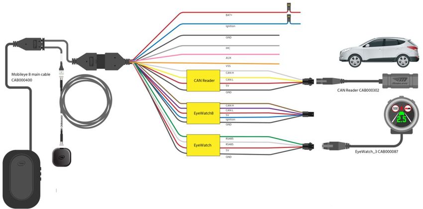
Mobileye 8 Connect | January 2022         MOBILEYE, AN INTEL COMPANY
                       Technical Installation Guide (3G) v2.1    WWW.MOBILEYE.COM

7.3 SYSTEM CALIBRATION                                                            23
7.3.1 LOGIN                                                                       23
7.3.2 INSTALLATION SITE                                                           24
7.3.3 VEHICLE SELECTION                                                           26
7.3.4 CONNECTION TO SEEQ                                                          27
7.3.5 VEHICLE INFORMATION                                                         28
7.3.6 PROFILE SELECTION                                                           29
7.3.7 ANALOG INSTALLATION                                                         30
7.3.8 SIGNAL TEST                                                                 31
7.3.8.1 SIGNAL TEST TROUBLESHOOTING:                                              32
7.3.9 CALIBRATION                                                                 33
7.3.9.1 STEP 1 – TAC ASSEMBLY                                                     33
7.3.9.2 STEP 2 – CAMERA ATTACHMENT                                                34
7.3.9.3 STEP 3 – GPS ATTACHMENT                                                   35
7.3.9.4 STEP 4 – MEASUREMENTS                                                     37
7.3.9.5 STEP 5 – CAMERA ANGEL ADJUSTMENT                                          41
7.3.9.6 STEP 6 – CAR HOOD                                                         42
7.3.9.7 STEP 7 – CALIBRATION                                                      42

8.   VALIDATION                                                                   45
8.1 GENERAL                                                                       45
8.2 OPERATION                                                                     45

9.   APPENDIX A - CAN READER                                                      48
9.1 MOBILEYE 8 CONNECT CAN READER CABLE (CAB000302)                               48
9.2 CAN READER INSTALLATION (CAB000302)                                           48
9.3 TECHNICAL SPEC                                                                49

10. APPENDIX B – UP/DOWN CONFIGURATION                                            50

11. APPENDIX C – EYENET HOLDER (ASY000451)                                        53
11.1 COMPONENT'S OVERVIEW                                                         53
11.2 ASSEMBLY                                                                     53

12. APPENDIX D – CALIBRATION TOOL                                                 55

13. TROUBLESHOOTING                                                               57
13.1 TROUBLESHOOTING                                                              57

14. TECHNICAL SPECIFICATION                                                       59

Page 3 of 61      |     Technical Installation Guide (3G) v2.1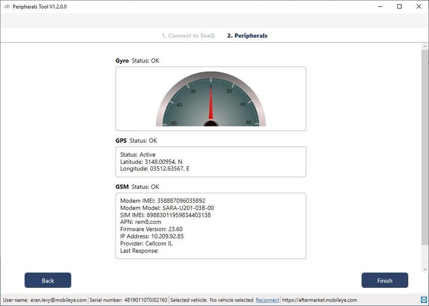
Mobileye 8 Connect | January 2022                     MOBILEYE, AN INTEL COMPANY
                       Technical Installation Guide (3G) v2.1                WWW.MOBILEYE.COM

   1. Warnings

   1.1    General

   Mobileye 8 Connect is Mobileye’s new driver assistance system, containing the latest
   iteration in Mobileye’s state-of-the-art machine vision software – the EyeQ®4 system-on-
   chip.
   Mobileye 8 Connect alerts the driver, aurally and visually, to certain potentially dangerous
   situations on the road; the greater the danger, the more ‘urgent’ the warning.

   Mobileye 8 Connect is not an automated driving system. It does not replace the driver nor
   allow the driver to be any less vigilant or alert to the road than he/she would otherwise
   be. It does not reduce the driver’s responsibility for driving properly, nor his/her liability
   for driving improperly or unlawfully. In particular, the driver should ensure not to be
   distracted from the road by the Mobileye 8 Connect display unit.
   Mobileye 8 Connect works best on paved roads with clear lane markings. Even then,
   Mobileye cannot guarantee 100% accuracy nor the absence of false positives (‘seeing’
   something that’s not there) or false negatives (failing to ‘see’ something that is there),
   especially in adverse road or weather conditions.
   Mobileye 8 Connect is designed to detect only fully visible vehicles and fully visible
   pedestrians and bicycles (both in daylight and at night). It is not designed to detect
   crossing, oncoming, or passing vehicles.

Page 4 of 61      |    Technical Installation Guide (3G) v2.1
Mobileye 8 Connect | January 2022                   MOBILEYE, AN INTEL COMPANY
                        Technical Installation Guide (3G) v2.1              WWW.MOBILEYE.COM

   1.2     Installation and safety instructions

✓ Mobileye 8 Connect installation must be carried out by an authorized Mobileye 8 Connect
  dealer or Installer.
✓ Do not transfer Mobileye 8 Connect to another vehicle after installation.
✓ The Mobileye 8 Connect GSM Nano SIM card will work only with the Mobileye 8 Connect
  unit with which it is supplied; do not use the SIM for other purposes or with other
  Mobileye 8 Connect units.
✓ Operate Mobileye 8 Connect only with 12VDC~24VDC power.
✓ Do not cover or obstruct the Camera Unit or Display and Control Unit.
✓ Use proper tools.
✓ Use only an LED voltage tester or digital multi meter. Do not use a light bulb voltage tester.
✓ Pay attention to unusual color cables, for example: yellow cables belong to air bags; two
  twisted wires usually belong to different (digital) sensors.
✓ Before disconnecting the battery or radio connectors make sure to have the radio code in
  hand.
✓ Do not disconnect any plug or connector in the vehicle while the car’s ignition switch is
  on.
✓ Use protective gloves when handling the camera unit to protect against heat burns.

Page 5 of 61      |     Technical Installation Guide (3G) v2.1
Mobileye 8 Connect | January 2022        MOBILEYE, AN INTEL COMPANY
                         Technical Installation Guide (3G) v2.1   WWW.MOBILEYE.COM

   2. Component's overview
  Package List                              Component                    Mobileye P/N

 Master Camera unit                                                      ASY0000000000805

    display unit –
                                                                             ASY000130
      EyeWatch

      Main cable                                                          CAB000400 Rev3.3

 GPS Cable & Module                                                          CAB000402

     Signals cable                                                        CAB000371 Rev6.3

     CAN Reader                                                          CAB000302 Rev.0.3

                                                                          Fuse - ITM000205
                                                                         Fuse holder (Red) -
 External fuse holders
                                                                             ITM000206
     with 2A fuses
                                                                         Fuse holder (Blue) -
                                                                             ITM000207

   3M VHB Surface
                                                                             ITM000024
      Cleaner

                                                                      ITM000786 – Ring Ferrite \
        Ferrite                                                             ITM000777

Page 6 of 61         |   Technical Installation Guide (3G) v2.1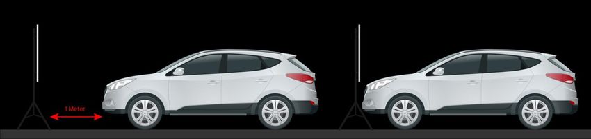
Mobileye 8 Connect | January 2022                               MOBILEYE, AN INTEL COMPANY
                      Technical Installation Guide (3G) v2.1                          WWW.MOBILEYE.COM

                                                Installer Kit

                                                             used for system
     EyeNET
                                                         installation, calibration,             EyeNET0001
                                                            and configuration

                                                          used for both the main
                                                          camera attachment to
       TAC                                                          the
                                                                                                 TACS00003
                                                          windshield (reference
                                                         point) and for calibration
                                                                calculation

             NOTE
               ✓ The Mobileye EyeNET is not part of the Mobileye 8 System and is sold
                 separately.
               ✓ If LAN port is not available in your laptop, an Ethernet to USB adapter can be

Page 7 of 61    |     Technical Installation Guide (3G) v2.1
Mobileye 8 Connect | January 2022                         MOBILEYE, AN INTEL COMPANY
                          Technical Installation Guide (3G) v2.1                    WWW.MOBILEYE.COM

    3. Software download & installation

Mobileye 8 Connect series uses a dedicated applications for configuration and calibration*.
The applications are part of the Mobileye Installation Center.
The software installer is available in our website under "support" tab or in the following direct link:

https://www.mobileye.com/support/

     NOTE
     Please make sure you have Administrator Privileges before installing the Mobileye IC
     application, if not, please contact your IT department for further assistance.

     NOTE
     To keep the most up to date version of the IC application, login with your login details
     to enable to automatic update. If an update is available, follow the on-screen
     instruction.

Page 8 of 61        |     Technical Installation Guide (3G) v2.1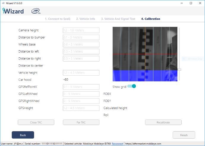
Mobileye 8 Connect | January 2022        MOBILEYE, AN INTEL COMPANY
                   Technical Installation Guide (3G) v2.1   WWW.MOBILEYE.COM

   4. Connection Scheme

   4.1   CAN-bus installation scheme

   4.2   Mix installation scheme (Analog + CAN-bus)

Page 9 of 61   |   Technical Installation Guide (3G) v2.1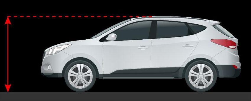
Mobileye 8 Connect | January 2022         MOBILEYE, AN INTEL COMPANY
                    Technical Installation Guide (3G) v2.1    WWW.MOBILEYE.COM

   4.3   Analog installation scheme

Page 10 of 61   |    Technical Installation Guide (3G) v2.1
Mobileye 8 Connect | January 2022 MOBILEYE, AN INTEL COMPANY
Technical Installation Guide (3G) v2.1 WWW.MOBILEYE.COM
5. Connection description
The following paragraphs describe in detail the function and connections of the system’s
components.
5.1 Main unit connections (CAB000400 Rev3.3)
Wire Name & Function Wire color Connector Connection To
Signals - (14 pin connector) Black J1 Vehicle signals cable (CAB000371
rev.6.3)
GPS - (5 pins White connector) Black P2 GPS Module and extension cable
CAB00402 Rev 1.1
Table 1: Mobileye 8 Connect cable connections
5.2 Mobileye 8 Connect signals cable (CAB000371 Rev6.3)
The Mobileye 8 Connect signals cable splits into a few cables which connect to the vehicle
power source, to the vehicle CAN-bus (Via CAN Reader connector) , to the vehicle analog
speed signal, to the vehicle high-beams (for IHC), to one of the vehicle’s analog signals if
required (or both analog left- and right-turn indicator signals via diode), to the EyeWatch
display unit (via 4 pin male connector labeled as "EyeWatch" and it contains a 6-pin female
connecter labeled “EyeWatch 8” to provide future connection for new EyeWatch unit.
A detailed description of each of the wires in the analog cable can be found in the following
table below:
Page 11 of 61 | Technical Installation Guide (3G) v2.1Mobileye 8 Connect | January 2022 MOBILEYE, AN INTEL COMPANY
Technical Installation Guide (3G) v2.1 WWW.MOBILEYE.COM
Wire Name & Function Wire color Connector Connection To
BAT+ (12/24V) Red - Vehicle`s constant power (Battery)
GND Black - Vehicle`s GND (BAT-)
Ignition (12/24V) Blue - Vehicle`s ignition signal
CAN B H White 4pin CAN Reader
CAN B L Yellow 4pin CAN Reader
5V for CAN Reader Red 4pin CAN Reader
GND for CAN Reader Black 4pin CAN Reader
VSS Orange - Vehicle`s Analog speed signal
CAN A High Purple 6pin EyeWatch 8
CAN A Low Brown 6pin EyeWatch 8
5V for EyeWatch 8 Red 6pin EyeWatch 8
GND for EyeWatch 8 Black 6pin EyeWatch 8
AUX (Analog Input) Pink - 1 analog signal input (or both Left
and Right Turn indicators analog
input via Diode)
IHC – (Analog Output) Gray - Vehicle`s high beams via external
relay or connection to any 3rd
party device
RS-485 High Green 4pin EyeWatch 3
RS-485 Low White 4pin EyeWatch 3
RS-485 GND Black 4pin EyeWatch 3
RS-485 5V DC Red 4pin EyeWatch 3
Table 2: Mobileye 8 Connect analog signals cable connection
Page 12 of 61 | Technical Installation Guide (3G) v2.1Mobileye 8 Connect | January 2022 MOBILEYE, AN INTEL COMPANY
Technical Installation Guide (3G) v2.1 WWW.MOBILEYE.COM
5.3 Ferrite
5.4 Ferrite for power sources – Model 1 (ITM000777)
Note: The Ferrite size and shape may vary different between different Ferrite models.
5.4.1 Instructions for Power Sources (CAB000371)
Please follow the instructions bellow for the two ferrites installation:
1. Open the Ferrite using a small flat screwdriver.
2. Place both Mobileye BAT+ wire and Ignition wire
(CAB000371) together inside the first Ferrite.
3. Locate the Ferrite 5cm from the Mobileye CAB000371
label
4. Wrap the BAT+ and Ignition wires through the Ferrite 4 times
and around the outside of the Ferrite 3 times, as shown in
the figures
5. Lock the Ferrite
6. Open the second Ferrite using the supplied Key or small flat
screwdriver
7. Place the Mobileye GND wire in the second Ferrite (locate
the Ferrite filters 5cm from the Mobileye CAB000371
label).
8. Wrap the GND wire through the Ferrite 4 times and around
the outside of the Ferrite 3 times, as shown in the figures
9. Close the Ferrite
NOTE
✓ Ferrite installation on power lines are mandatory in CE marking countries.
✓ Ferrite installations are not mandatory for FCC and E-Mark certificates.
Page 13 of 61 | Technical Installation Guide (3G) v2.1Mobileye 8 Connect | January 2022 MOBILEYE, AN INTEL COMPANY
Technical Installation Guide (3G) v2.1 WWW.MOBILEYE.COM
5.5 Ferrite for power sources– Model 2 (ITM000786)
Note: The Ferrite size and shape may vary different between different Ferrite models.
5.5.1 Instructions for Power Sources (CAB000371)
Please follow the instructions bellow for the two ferrites installation:
1. Open the Ferrite using a small flat screwdriver.
2. Place both Mobileye BAT+ wire and Ignition wire
(CAB000371) together inside the first Ferrite.
3. Locate the Ferrite 5cm from the Mobileye CAB000371 label
4. Wrap the BAT+ and Ignition wires through the Ferrite 2 times and around the outside of
the Ferrite 1 times, as shown in the figures
5. Lock the Ferrite
6. Open the second Ferrite using the supplied Key or small flat screwdriver
7. Place the Mobileye GND wire in the second Ferrite (locate
the Ferrite filters 5cm from the Mobileye CAB000371
label).
8. Wrap the GND wire through the Ferrite 2 times and around the outside of the Ferrite 1
times, as shown in the figures
9. Close the Ferrite
NOTE
✓ Ferrite installation on power lines are mandatory in CE marking countries.
✓ Ferrite installation are not mandatory for FCC and E-Mark certificates.
Page 14 of 61 | Technical Installation Guide (3G) v2.1Mobileye 8 Connect | January 2022 MOBILEYE, AN INTEL COMPANY
Technical Installation Guide (3G) v2.1 WWW.MOBILEYE.COM
5.6 EyeWatch – display and control unit (CAB000087)
The EyeWatch is connected to the Mobileye 8 Connect EyeWatch female connector (J1)
using the EyeWatch connecting cable male connector (J1).
Table 3: EyeWatch connections
Wire name Wire color Connector Connection to
EyeWatch Cable (CAB000087) Black J1 - Female EyeWatch 4pin male connector in
CAB000371
EyeWatch (CAB000371) Black J1 – Male ME8 Signals cable 4 Pin connector for
EyeWatch unit
5.7 CAN Reader – (CAB000302)
The Mobileye CAN-Sensor is a non-intrusive solution for CAN-bus connection.
The Mobileye CAN Sensor will allow you to better handle a CAN-bus reading by simply placing
the sensor on the vehicle CAN-bus wires without any wire cutting or pinching.
Wire name Wire color Connector Connection to
Power sources and signals cable Red, Black, Male Mobileye CAN Sensor
(CAB000371) Yellow and
White
Mobileye CAN Sensor (CAB0003002) Black Female Power sources and signals cable
(CAB000371)
Page 15 of 61 | Technical Installation Guide (3G) v2.1Mobileye 8 Connect | January 2022 MOBILEYE, AN INTEL COMPANY
Technical Installation Guide (3G) v2.1 WWW.MOBILEYE.COM
5.8 EyeNET – (EYENET0001 / CAB000613)
The Mobileye 8 Connect service port female connector (P2) is used to connect to the
Mobileye EyeNET short cable male connector labeled “MOBILEYE8 SIDE” (J5).
Wire name Wire color Connector Connection to
EyeNET short cable (BRD000350) Brown Male Mobileye 8 Connect service port
EyeNET Ethernet LAN port Female LAN port for Ethernet cable between the
EyeNET and the PC
Mobileye 8 Connect service port Female EyeNET cable
EyeNET- Connection Scheme
Table 4: EyeNET connections
Page 16 of 61 | Technical Installation Guide (3G) v2.1Mobileye 8 Connect | January 2022 MOBILEYE, AN INTEL COMPANY
Technical Installation Guide (3G) v2.1 WWW.MOBILEYE.COM
6. Guidelines
6.1 Site preparation
✓ Make sure the vehicle is parked on a flat surface (no slope).
✓ Check vehicle speed signal availability (either by CAN-bus or by Analog) to
determine which type of installation will be for the Master camera (CAN, Analog,
Mix).
6.2 Connecting to the vehicle’s signals
NOTE
• DO NOT connect both BAT+ and Ignition to the same power source. Each lead must be
connected to its appropriate source. Failure to do so will result in system malfunction.
• Identifying the vehicle’s electrical signals requires having the keys in the ignition in the
ACC (Accessory) position or ignition ON. Make sure the car headlights and/or any other
power consuming devices/applications, e.g. air conditioning, are turned off during
Mobileye 8 Connect installation to prevent battery drainage.
Please ensure to identify the Mobileye 8 Connect cables according to table below.
Identified vehicle’s signals Wires label Wires color
Vehicle battery (Constant 12V~24V) via 2A fuse BAT+ Red
Ignition (12V~24V) via 2A fuse Ignition Blue
Vehicle GND GND Black
CAN B High CAN Reader White
CAN B Low CAN Reader Yellow
Page 17 of 61 | Technical Installation Guide (3G) v2.1Mobileye 8 Connect | January 2022 MOBILEYE, AN INTEL COMPANY
Technical Installation Guide (3G) v2.1 WWW.MOBILEYE.COM
6.3 Installing the EyeWatch
NOTE
❖ The EyeWatch unit should be placed in a location that does not obstruct the
driver’s field of vision
❖ The EyeWatch should not be placed in front of the air-bags operational space
as it may otherwise prevent the airbag from fully opening or cause injury
during air-bag activation
Select the optimal location for the EyeWatch attachment:
1. The EyeWatch should be placed on the dashboard or windshield at a location within
the driver’s field of view, conveniently visible while driving, and allowing access to its
controls while sitting comfortably in the driver’s seat (the EyeWatch mounting angle
is adjustable by the installer — a Philips screwdriver is required)
2. Clean the selected location with the provided 3M VHB Surface cleaner
3. Attach the EyeWatch at the selected place (after removing the protective cover
from the adhesive tape)
4. Remove the transparent protecting covering from the display surface
5. Insert the EyeWatch cable (CAB000087) behind the vehicle trimmings so that it
reaches the EyeWatch connector of the Mobileye 8 Connect cable (CAB000400)
Page 18 of 61 | Technical Installation Guide (3G) v2.1Mobileye 8 Connect | January 2022 MOBILEYE, AN INTEL COMPANY
Technical Installation Guide (3G) v2.1 WWW.MOBILEYE.COM
6.4 Installing the Mobileye 8 Connect main unit (camera)
NOTE
Selecting the optimal location for the main unit is critical and can affect system
performance.
Please ensure to comply with the following guidelines.
❖ Minimum height for camera location is 1.2 meters (3.9 feet).
Maximum height for camera location is 1.8 meter (5.9 feet).
NOTE
In extreme cases and upon approval of Mobileye support team, it is possible to install the
camera above 1.8 meters BUT this will void any REM data which can affect the project
target.
❖ The unit must be in an area of the windshield which the windshield wipers reach.
❖ The unit should preferably be located at the center of the windshield.
Installing the unit off-center in a convex windshield will result an improper field of
view, which will affect system performance. The camera’s lens should always face
straight ahead.
❖ Off-center installation is allowed up to 8%
EXAMPLE: if the vehicle width is 200cm (2M), camera can be attached up to 16 cm
from the windshield center (200*0.08=16). Vehicle width in cm X 0.08 = MAX
OFFSET
❖ Camera roll-up is allowed up to 2°; if the camera roll is higher than 2°, the calibration
will fail.
❖ There should be no obstruction, such as stickers or darkened windshield areas, in
front of the main unit.
❖ In tall commercial vehicles that do not have an engine hood blocking the camera’s
field of view, the main unit can be placed on the lower part of the windshield;
however, all the above-mentioned requirements must nonetheless be considered. In
this case, you can modify the main unit cable to the "DOWN" position. “DOWN”
means that after the main unit installation, the main cable exits from downwards
instead of upwards (by default the cable exits upward from the “UP” position).
Page 19 of 61 | Technical Installation Guide (3G) v2.1Mobileye 8 Connect | January 2022 MOBILEYE, AN INTEL COMPANY
Technical Installation Guide (3G) v2.1 WWW.MOBILEYE.COM
NOTE
Attaching the camera unit to the windshield should take place only after receiving a live
streaming video during calibration process.
The following paragraphs present the function of each cable and guide you through the
actual connection procedures with the vehicle’s signals.
1. Identify the wires in the vehicle that carry the required electrical signals (according
to the table above).
2. After identifying the required signal's locations in the vehicle, pass the Mobileye 8
Connect cable (CAB000400) behind the vehicle trimmings so that it reaches all
vehicle signals (it is recommended that you hang the Mobileye 8 Connect main unit
on the rear-view mirror or place it on the dashboard before passing the cable behind
the vehicle trimmings).
3. Firmly connect the appropriate wire from the Mobileye 8 Connect signals cable
(CAB000371) to the identified vehicle signal.
4. Each wire in the Mobileye 8 Connect signals cable (CAB000371) mentioned above has
a unique color. Make sure to connect the correct vehicle signal to its appropriate wire
according to the table in page 12.
5. Keep the Mobileye 8 Connect EyeCAN connector & EyeWatch connectors easily
accessible.
NOTE
• Connect each power source lead to its appropriate connection in the vehicle.
• Make sure the 2A fuses are kept easily accessible
• Wires colors are not guaranteed. Always double-check wires’ labels
• Always check the Mobileye vehicle database for CAN-bus availability before
installation is started
Page 20 of 61 | Technical Installation Guide (3G) v2.1Mobileye 8 Connect | January 2022 MOBILEYE, AN INTEL COMPANY
Technical Installation Guide (3G) v2.1 WWW.MOBILEYE.COM
7. Installation & Calibration procedure
7.1 Removing unit’s back cover
As part of the Mobileye 8 Connect calibration process, the camera angle must be adjusted
as outlined below.
To access the camera angle adjustment`s screw you must remove the main unit’s back
cover.
To remove the back cover:
①
Using a small flat screwdriver,
slide and push out the oval
cover
②
Using a small Philips
screwdriver, unscrew the 3
screws and remove the main
back cover
Page 21 of 61 | Technical Installation Guide (3G) v2.1Mobileye 8 Connect | January 2022 MOBILEYE, AN INTEL COMPANY
Technical Installation Guide (3G) v2.1 WWW.MOBILEYE.COM
7.2 Communication / connection phase
Mobileye 8 Connect service port interface is used to communicate with the Mobileye
system.
The EyeNET adapter enables fast connection between the Mobileye 8 Connect and
Mobileye software running on a computer for system calibration and configuration.
Figure 1 – connection method with EyeNET adapter
NOTE
• EyeNET connection to the Mobileye 8 Connect unit should only be performed when
system power is off!
• Make sure you connect the short flex cable (BRD000350) correctly:
❖ One side to the Mobileye 8 unit labeled as “MOBILEYE8 SIDE”
❖ The other side to the EyeNet Box (BRD000344) labeled as “EYENET SIDE”
NOTE
Internet access is mandatory to configure and calibrate Mobileye 8 Connect.
Page 22 of 61 | Technical Installation Guide (3G) v2.1Mobileye 8 Connect | January 2022 MOBILEYE, AN INTEL COMPANY
Technical Installation Guide (3G) v2.1 WWW.MOBILEYE.COM
7.3 System Calibration
7.3.1 Login
Open the Installation Center application on your computer and login using your personal
login details
youremail@email.com
→ Click "Login" to continue
***********
Page 23 of 61 | Technical Installation Guide (3G) v2.1Mobileye 8 Connect | January 2022 MOBILEYE, AN INTEL COMPANY
Technical Installation Guide (3G) v2.1 WWW.MOBILEYE.COM
7.3.2 Installation site
Choose your installation site from the dropdown list
Click the vehicle database icon to open the Mobileye vehicle database and browse to find
the correct profile of the vehicle you are installing.
In the vehicle database, you can find the following information:
❖ Vehicle make/year/model
❖ CAN-bus signals availability
❖ CAN-bus wires location + picture
❖ CAN-bus baud rate
NOTE
• When clicking the "vehicle database" button, no physical connection is required.
• It is possible to continue and open the IC Wizard application directly from the vehicle
database.
• If you are already connected to a Mobileye 8 Connect system and have completed the
physical connections, you may skip the "vehicle database" and click the "wizard"
button to immediately start the installation
Page 24 of 61 | Technical Installation Guide (3G) v2.1Mobileye 8 Connect | January 2022 MOBILEYE, AN INTEL COMPANY
Technical Installation Guide (3G) v2.1 WWW.MOBILEYE.COM
NOTE
When clicking the "Wizard" button you must be physically connected to a Mobileye 8 Connect
system and the system power must be on to continue the calibration process. You will have an
option to browse and choose the correct profile of the vehicle you are installing during a
standard Wizard run as well.
Page 25 of 61 | Technical Installation Guide (3G) v2.1Mobileye 8 Connect | January 2022 MOBILEYE, AN INTEL COMPANY
Technical Installation Guide (3G) v2.1 WWW.MOBILEYE.COM
7.3.3 Vehicle selection
Choose the correct vehicle profile from the vehicle database.
The Mobileye vehicle database contain CAN information such as: available signals, CAN-bus
wires location, bus speed, CAN-bus wires colors or pin number if available and pictures of
the vehicle & CAN wires location.
NOTE
In the event the vehicle into which you are installing is not in the vehicle database, you can
either try a similar profile or contact Mobileye support for help with creating a new profile.
→ Click "Go To App" to continue
Page 26 of 61 | Technical Installation Guide (3G) v2.1Mobileye 8 Connect | January 2022 MOBILEYE, AN INTEL COMPANY
Technical Installation Guide (3G) v2.1 WWW.MOBILEYE.COM
7.3.4 Connection to SeeQ
The app will check:
communication status with Mobileye’s system and provide system information such as:
❖ Connection status
❖ System serial number
❖ System firmware version
- Physical connection and communication of the below peripherals with the app
❖ Gyro
❖ GPS
❖ GSM
NOTE
If you click the "retry" button, the app will try to reestablish communication and display the
system information if successful.
→ Click "Next" to continue
Page 27 of 61 | Technical Installation Guide (3G) v2.1Mobileye 8 Connect | January 2022 MOBILEYE, AN INTEL COMPANY
Technical Installation Guide (3G) v2.1 WWW.MOBILEYE.COM
7.3.5 Vehicle information
Enter the license number, VIN number and choose the country from the dropdown menu.
→ Click "Next" to continue
Page 28 of 61 | Technical Installation Guide (3G) v2.1Mobileye 8 Connect | January 2022 MOBILEYE, AN INTEL COMPANY
Technical Installation Guide (3G) v2.1 WWW.MOBILEYE.COM
7.3.6 Profile selection
The software will remember and display all the vehicle and profile information you chose
earlier. You can always choose a new profile or modify your earlier selection at this time.
Click → "Burn selected profile" to burn and save the profile data into the Mobileye system.
NOTE
• You can change and burn different profiles until finding the correct profile.
• You cannot proceed with system calibration until you pass the signals test.
Page 29 of 61 | Technical Installation Guide (3G) v2.1Mobileye 8 Connect | January 2022 MOBILEYE, AN INTEL COMPANY
Technical Installation Guide (3G) v2.1 WWW.MOBILEYE.COM
7.3.7 Analog installation
In a case you install the unit in vehicle which speed is not available by CAN, please locate the
VSS signal in the vehicle, choose the most similar vehicle profile from the vehicle DB and
change the Speed input from "Digital" to "Analog", VSS rate field will be available to be filled
according the specific VSS of the relevant vehicle.
If you don’t know the vehicle VSS rate, set the value to 5000, Burn the profile as set and
check the Vehicle speed vs the Mobileye Installation Center shown speed, if necessary,
please adjust the rate so the speed shown will be accurate.
Page 30 of 61 | Technical Installation Guide (3G) v2.1Mobileye 8 Connect | January 2022 MOBILEYE, AN INTEL COMPANY
Technical Installation Guide (3G) v2.1 WWW.MOBILEYE.COM
7.3.8 Signal Test
Verify that all signals are detected by the Mobileye system.
Activate each signal and an icon will be shown when it is detected by the Mobileye
system.
Speed signal verification - drive and confirm speed indication in the Mobileye setup wizard
approximately matches the speed of the car shown by the speedometer.
NOTE
• Signals activation are possible only after the speed signal is verified and marked as
• To proceed to the next step, the full signals test must be successfully completed
Click "Reset test" button if you would like to retest.
→ Click "Next" to continue
Page 31 of 61 | Technical Installation Guide (3G) v2.1Mobileye 8 Connect | January 2022 MOBILEYE, AN INTEL COMPANY
Technical Installation Guide (3G) v2.1 WWW.MOBILEYE.COM
7.3.8.1 Signal Test Troubleshooting:
If the signals test failed in all or some of the inputs, please follow the next steps and press
“reset test”:
• Before any signal test activation, wait until the speed signal green V icon will be shown
and only then test the other signals activation.
• Check your connections- make sure the CAN sensor is connected correctly.
• Try to switch CAN High and CAN Low connections- try to flip the CAN Sensor on the
CAN wires and reset test again.
• Make sure you connected to the CAN wires as described in the Mobileye Vehicle
Database.
• Check the chosen profile- make sure you chose the correct profile, if needed try to
choose other similar profile, burn it and check the signals test again.
→ Click "Next" to continue
Page 32 of 61 | Technical Installation Guide (3G) v2.1Mobileye 8 Connect | January 2022 MOBILEYE, AN INTEL COMPANY
Technical Installation Guide (3G) v2.1 WWW.MOBILEYE.COM
7.3.9 Calibration
7.3.9.1 Step 1 – TAC assembly
Place the TAC target in front of & exactly at the center of the vehicle.
When TAC is assembled and open correctly the bottom part of the checkered
board TAC should be 90 cm from ground or 165 cm if the TAC is opened and
flipped to high level (depending on the camera height).
Mount the camera on the windshield according to Mobileye’s guidelines as
follows:
Page 33 of 61 | Technical Installation Guide (3G) v2.1Mobileye 8 Connect | January 2022 MOBILEYE, AN INTEL COMPANY
Technical Installation Guide (3G) v2.1 WWW.MOBILEYE.COM
7.3.9.2 Step 2 – Camera attachment
Use the surface cleaner supplied in the kit to clean the attachment area of the windshield
and then use a dry paper towel to dry the area and remove residue before attaching the
camera.
Mount the camera using the live image feed from the camera unit, showing the grid lines
over the TAC target. This image feed will assist you in mounting the camera correctly and
within the allowed camera tilt/roll of up to 2°. Use the grid to properly attach the camera
with as little tilt/roll as possible.
Attach the main camera unit; lining up the IC Wizard Yellow line exactly with the camera
location on the TAC.
For example:
If the camera is mounted exactly in the center of the windshield, the yellow line should be in
the center of the TAC target.
If the camera is mounted off-center, make sure this offset is reflected in the yellow line
location on the TAC target.
Center 5cm to the right 10cm to the right
Page 34 of 61 | Technical Installation Guide (3G) v2.1Mobileye 8 Connect | January 2022 MOBILEYE, AN INTEL COMPANY
Technical Installation Guide (3G) v2.1 WWW.MOBILEYE.COM
Deviation Offset
Optimal- center of the windshield, if center not possible, according to the vehicle width:
a. If the vehicle width measurement is up to 1.67 meters- camera can be attached
up to 10cm from the windshield center MAX.
b. If the vehicle width measurement is more than 1.67 meters- camera can be
attached up to 8% of the vehicle width measurement.
Vehicle width in cm X 0.08 = MAX OFFSET
7.3.9.3 Step 3 – GPS attachment
Use the surface cleaner supplied in the kit to clean the attachment area of the windshield
and then use a dry paper towel to dry the area and remove residue before attaching the
GPS attachment.
Attach the GPS module mount using the 3M double-sided tape.
Make sure the GPS is facing up and attached in cleared area on the windshield and as far as
possible from both the Mobileye 8 Connect and the vehicle instrument cluster (bottom of
the windshield in passenger's side).
Make sure you attached the GPS module to the windshield properly- verify there are no air-
bubbles between the GPS unit and the windshield
Please Note: GPS module can't be attached more than 0.49m ahead from the camera unit.
(Camera distance to bumper – GPS distance to bumper < 0.49m)
Page 35 of 61 | Technical Installation Guide (3G) v2.1Mobileye 8 Connect | January 2022 MOBILEYE, AN INTEL COMPANY
Technical Installation Guide (3G) v2.1 WWW.MOBILEYE.COM
GPS attachment on Flat Windshield
GPS attachment on vehicles with flat windshield should be located on the upper-left (driver
perspective) side of the windshield, high as the GPS cable allow.
GPS attachment on vehicles with flat windshield should be located only in area that not
covered by the vehicle wipers.
Please bellow illustration for example
Green- GPS attachment allowed
Red- GPS attachment not allowed
Page 36 of 61 | Technical Installation Guide (3G) v2.1Mobileye 8 Connect | January 2022 MOBILEYE, AN INTEL COMPANY
Technical Installation Guide (3G) v2.1 WWW.MOBILEYE.COM
7.3.9.4 Step 4 – measurements
NOTE
Entering any measurement that is not in the acceptable range or not in the correct format will
be highlighted in red and will not let you continue to the next step
Enter each vehicle measurement in the correct field:
❖ Camera height
Measure the camera height from the camera lens to the ground.
Page 37 of 61 | Technical Installation Guide (3G) v2.1Mobileye 8 Connect | January 2022 MOBILEYE, AN INTEL COMPANY
Technical Installation Guide (3G) v2.1 WWW.MOBILEYE.COM
❖ Distance to bumper (the distance from the camera to the front bumper).
Measure the horizontal distance from the camera lens to the vehicle’s front bumper
edge.
❖ Wheels Base (width of the vehicle wheels)
Measure the distance between the outer edges of the front wheels.
Page 38 of 61 | Technical Installation Guide (3G) v2.1Mobileye 8 Connect | January 2022 MOBILEYE, AN INTEL COMPANY
Technical Installation Guide (3G) v2.1 WWW.MOBILEYE.COM
❖ Distance to left, distance to right (the camera distance from the left and right
windshield edge).
Measure the lateral distance from the camera lens to both left & right windshield
edges.
PLEASE NOTE: Left & Right should be measure from the outside of the vehicle but
should be insert to the software as driver perspective sides (see Left &Right on the
illustration bellow.
Right Left
❖ Vehicle Height
Measure the distance from ground to the top of the vehicle.
Page 39 of 61 | Technical Installation Guide (3G) v2.1Mobileye 8 Connect | January 2022 MOBILEYE, AN INTEL COMPANY
Technical Installation Guide (3G) v2.1 WWW.MOBILEYE.COM
❖ GPS Measurements (the GPS location)
In this section, measure the exact GPS location on the Windshield.
GPS to Bumper measurement:
Measure the horizontal distance from the GPS unit to the
vehicle’s front bumper edge (Distance to Bumper)
Please Note: GPS module can't be attached more than 0.49m ahead from the camera unit.
(camera distance to bumper – GPS distance to bumper < 0.49m)
GPS to Left & Right Wheel measurement
Measure the GPS unit distance from Left & Right windshield
edge.
PLEASE NOTE: Left & Right should be measure from the outside
of the vehicle but should be insert to the software as driver
perspective sides (see Left &Right on the illustration bellow.
Right Left
Page 40 of 61 | Technical Installation Guide (3G) v2.1Mobileye 8 Connect | January 2022 MOBILEYE, AN INTEL COMPANY
Technical Installation Guide (3G) v2.1 WWW.MOBILEYE.COM
GPS Height measurement-
Measure the exact GPS height from to ground.
NOTE
If the GPS measurements will be incorrect, the ME8 data will be useless and the installer will
have to go back and set the correct measurements.
7.3.9.5 Step 5 – Camera angel adjustment
After measuring the camera height and entering it into the Wizard, mark the camera height
on the TAC board using a black tape and manually adjust the camera’s lens so that the RED
line will be parallel to the height mark on the TAC.
Once the red line in the image is lined up with the marking you placed on the TAC, tighten
the camera angle adjustment screw.
Page 41 of 61 | Technical Installation Guide (3G) v2.1Mobileye 8 Connect | January 2022 MOBILEYE, AN INTEL COMPANY
Technical Installation Guide (3G) v2.1 WWW.MOBILEYE.COM
7.3.9.6 Step 6 – Car hood
Drag the scroll bar on the left side of the image to adjust the blue field and prevent the
camera from ‘seeing’ the hood of the vehicle.
See image below:
NOTE
Perform vehicle hood calibration only if the hood poses a permanent obstruction to the
camera’s field of view.
If no car engine hood is present in the image, car hood value should remain at the default value
of -120
7.3.9.7 Step 7 – Calibration
Once all these measurements have been entered, 2 calibration steps are required:
Close TAC Far TAC
1 Meter
Page 42 of 61 | Technical Installation Guide (3G) v2.1Mobileye 8 Connect | January 2022 MOBILEYE, AN INTEL COMPANY
Technical Installation Guide (3G) v2.1 WWW.MOBILEYE.COM
Close TAC
Place the TAC exactly in the center of the vehicle and close to the vehicle bumper.
Press “Close TAC” for close TAC calculation.
Far TAC
After the close TAC calculation has been successfully completed, a pop-message will appear.
Move the TAC 1-meter back Press “OK” and.
Page 43 of 61 | Technical Installation Guide (3G) v2.1Mobileye 8 Connect | January 2022 MOBILEYE, AN INTEL COMPANY
Technical Installation Guide (3G) v2.1 WWW.MOBILEYE.COM
Press “Far TAC” for far TAC calculation.
Step 9 – calibration results
Calibration results should meet the minimum requirements as follows:
1. FOE X optimal value is 0 )±15(
2. FOE Y optimal value is 0 (±10)
3. Calculated height- up to 3cm differences
4. Roll – up to 2°
If calibration results meet the minimum requirements mentioned above, calibration is
completed, click “Finish”
Page 44 of 61 | Technical Installation Guide (3G) v2.1Mobileye 8 Connect | January 2022 MOBILEYE, AN INTEL COMPANY
Technical Installation Guide (3G) v2.1 WWW.MOBILEYE.COM
8. Validation
8.1 General
Upon completion of the system calibration, the installer MUST validate all peripherals are
functional and valid using the new validation tool which can be found as part of Mobileye IC
prior to releasing the vehicle after the installation.
8.2 Operation
Click the icon to open the Peripherals tool
Page 45 of 61 | Technical Installation Guide (3G) v2.1Mobileye 8 Connect | January 2022 MOBILEYE, AN INTEL COMPANY
Technical Installation Guide (3G) v2.1 WWW.MOBILEYE.COM
The tool will check communication with the system and display the system s/n and FW
version following by the peripherals test and display the status of each component.
Click "Next" to continue to see each peripheral test results
Page 46 of 61 | Technical Installation Guide (3G) v2.1Mobileye 8 Connect | January 2022 MOBILEYE, AN INTEL COMPANY
Technical Installation Guide (3G) v2.1 WWW.MOBILEYE.COM
Note that due to the installation location such as underground parking or indoor garage and
GPS signal or cellular network is not available, the test status of the relevant component will
pass but no valid data will be displayed.
NOTE
If any of the peripherals found faulty, the Mobileye system must be replaced to complete the
installation.
Page 47 of 61 | Technical Installation Guide (3G) v2.1Mobileye 8 Connect | January 2022 MOBILEYE, AN INTEL COMPANY
Technical Installation Guide (3G) v2.1 WWW.MOBILEYE.COM
9. Appendix A - CAN Reader
9.1 Mobileye 8 Connect CAN Reader cable (CAB000302)
The Mobileye 8 Connect CAN-Reader is a new, non-intrusive solution for CAN-bus connection.
No more wrong connections, warranty violations or liability issues. The Mobileye CAN-Reader will
allow you to better handle a CAN-bus reading by simply placing the Mobileye CAN-sensor on the
vehicle CAN-bus wires without any wire cutting or pinching.
Benefits:
• Non-intrusive installation
• Simply install over the CAN-bus wires, no need to cut, strip, crimp or connect physically
• Read data thru the wire's isolation
• Fits most vehicles
• Supports all CAN-bus speeds
• Reliable CAN-bus data reading
• Fast and simple installation
9.2 CAN Reader installation (CAB000302)
1. Identify the vehicle CAN-bus wires
2. Untwist the CAN-bus wires over about 5cm
3. Place the CAN Reader over the CAN-bus wires as labeled on the CAN Sensor module
Page 48 of 61 | Technical Installation Guide (3G) v2.1Mobileye 8 Connect | January 2022 MOBILEYE, AN INTEL COMPANY
Technical Installation Guide (3G) v2.1 WWW.MOBILEYE.COM
Note: In some cases (if Er-20 shows on the EyeWatch display), you will need to switch between CAN High and CAN Low
wires
9.3 Technical Spec
CAN-sensor unit
Physical Characteristics
Length (entire cable): 1300mm
Width: 40mm Conformity
Height: 3mm 72/245/EEC The automotive directive for
electronic equipment which
Weight: 55g can build in road vehicles
Color: Black ISO 7637 Road Vehicles Electrical
Case material: Plastic Disturbances
ISO 11898 CAN for high-speed
Electrical Characteristics
communication
Input voltage: 4.5-5.5VDC ISO 9141 Road vehicles – Diagnostics
Input current: 5V 30mA systems. Requirements for
interchange of digital
Limited power source 200mA max at normal
information
and single fault
RoHS Yes
conditions
CAN High, CAN Low: Nominal input range: 0- WEEE Yes
5V EN60950-1:2006/A1:2010 Europe Safety
Common mode input Europe EMC
range: 7-12V ETSI 301489-1/-17
Environmental Characteristics FCC Verification part 15 USA EMC
subpart B
Operating temperature: -20°c to +85°c
Storage temperature: -40°c to +105°c
Page 49 of 61 | Technical Installation Guide (3G) v2.1Mobileye 8 Connect | January 2022 MOBILEYE, AN INTEL COMPANY
Technical Installation Guide (3G) v2.1 WWW.MOBILEYE.COM
10. Appendix B – up/down configuration
Mobileye 8 Connect is based on a smart camera, which is installed on the vehicle’s front
windshield. To suit all vehicle models (cars, trucks, buses) the smart camera main cable has two
configurations: up and down.
All Mobileye 8 Connect systems are supplied with a default up configuration. A
distributer/installer can change the up/down configuration at their discretion.
Changing the Mobileye 8 Connect up/down configuration is a simple but delicate procedure.
Instructions on how to change up/down configurations are listed below:
Required Tools:
✓ Philips Screwdriver (Tip Size = PH1)
✓ Flat Screwdriver (Tip Size = PH1)
① Using s flat screwdriver, slide and push out the ellipse cover
Page 50 of 61 | Technical Installation Guide (3G) v2.1Mobileye 8 Connect | January 2022 MOBILEYE, AN INTEL COMPANY
Technical Installation Guide (3G) v2.1 WWW.MOBILEYE.COM
② Using a Philips screwdriver, unscrew the 3 screws and remove the main back cover
③ Using a Philips screwdriver, unscrew to remove the main chassis from the frame
Page 51 of 61 | Technical Installation Guide (3G) v2.1Mobileye 8 Connect | January 2022 MOBILEYE, AN INTEL COMPANY
Technical Installation Guide (3G) v2.1 WWW.MOBILEYE.COM
④ gently remove the chassis from the frame
Note:
Do not unscrew the upper left and lower right screws. This will void the warranty!
⑤ Remove the main cable connector and connect it to the desired configuration
Camera up position
Camera down position
⑥ Once completed, reassemble all system components tightening the screws.
Page 52 of 61 | Technical Installation Guide (3G) v2.1Mobileye 8 Connect | January 2022 MOBILEYE, AN INTEL COMPANY
Technical Installation Guide (3G) v2.1 WWW.MOBILEYE.COM
11. Appendix C – EyeNET Holder (ASY000451)
The EyeNET holder used to hold the EyeNET and maintain a stable communication with the
Mobileye system.
11.1 Component's overview
SCR000120
MEC000950
11.2 Assembly
Attach the EyeNET holder on top of
the system`s metal body.
Page 53 of 61 | Technical Installation Guide (3G) v2.1Mobileye 8 Connect | January 2022 MOBILEYE, AN INTEL COMPANY
Technical Installation Guide (3G) v2.1 WWW.MOBILEYE.COM
Use to 2x screws to hold the EyeNET
Route the EyeNET flat cable trough
the designated gap and connect it in
both ends to the Mobileye system
and the EyeNET and continue with
the calibration process
Page 54 of 61 | Technical Installation Guide (3G) v2.1Mobileye 8 Connect | January 2022 MOBILEYE, AN INTEL COMPANY
Technical Installation Guide (3G) v2.1 WWW.MOBILEYE.COM
12. Appendix D – Calibration Tool
The Calibration Tool allows to recalibrate the ME8 units without deactivation vehicle profile
change such as windshield replacement.
1. To use the Calibration Tool run the app from the Installation Center main screen
Page 55 of 61 | Technical Installation Guide (3G) v2.1Mobileye 8 Connect | January 2022 MOBILEYE, AN INTEL COMPANY
Technical Installation Guide (3G) v2.1 WWW.MOBILEYE.COM
2. The tool will check communication with the system and display the system s/n and
FW version and display the status of each component.
Page 56 of 61 | Technical Installation Guide (3G) v2.1Mobileye 8 Connect | January 2022 MOBILEYE, AN INTEL COMPANY
Technical Installation Guide (3G) v2.1 WWW.MOBILEYE.COM
3. The camera attachment, measurements and calibration slide will show.
To attach, measure and calibrate, please refer to pages 32-42.
13. Troubleshooting
13.1 Troubleshooting
1. Installer kit:
• Check the TAC assembly.
• Check the EyeNET adapter and make sure the connectors are not damaged.
2. Installation issues:
If signal test fails, check that:
• You connected the correct CAN wires as instructed in the Mobileye Vehicle DB.
• Make sure you selected the correct profile for the vehicle. If necessary, try to use
another profile or proceed to CAN sniffing for a new profile creation.
You can also try to switch the CAN sensor position on the vehicle CAN wires (CAN H and CAN L).
3. Calibration and software issues:
Calibration issues can be related to the 4 parameters required.
• If FOE X is more than ±15, check the camera location on the windshield and the position
of the yellow line.
• If FOE Y value is more than ±10, check the measured camera height, the TAC height and
lens angle (red line).
Page 57 of 61 | Technical Installation Guide (3G) v2.1Mobileye 8 Connect | January 2022 MOBILEYE, AN INTEL COMPANY
Technical Installation Guide (3G) v2.1 WWW.MOBILEYE.COM
• The calculated camera height difference between what you measured and entered to
the system may be up to 3cm.
• If the roll value is more than 2°, make sure that the vehicle calibration surface is flat, and
the main camera unit attachment is not rolled.
• If you’re having issues with the Installation Center installation on your laptop, make sure
your laptop meets the minimum requirements.
• Communication issues can be related to your laptop LAN Port settings. Make sure the
LAN Port is set and adjust on your OS.
• If your laptop is not equipped with a LAN Port, use an Ethernet to USB adapter (not
included).
Page 58 of 61 | Technical Installation Guide (3G) v2.1Mobileye 8 Connect | January 2022 MOBILEYE, AN INTEL COMPANY
Technical Installation Guide (3G) v2.1 WWW.MOBILEYE.COM
14. Technical specification
Mobileye® 8 Connect™ (3G) | Technical Specification Sheet
Mobileye® 8 ConnectTM Main Unit
Physical Characteristics
Full System Electrical Characteristics
Length: 120mm
Input voltage 10-36VDC
Width (without lens): 78mm
Input current (full operation) 1A @ 12V, 0.5A @ 24V
Height: 44mm
Max power consumption 12W
Weight: 200g
Color: Black
Case material: Plastic & Aluminum
Cable length (CAB000400): 3m
Cable diameter: 5.8mm (±0.2)
Electrical Characteristics
Warning:
Input voltage: 10-36VDC Beware when removing the system after operation as it
Input current max: 12V > 700mA, 24V > 350mA may be hot.
Max power: 8.5W For your safety, please use gloves.
Ambient Temperature
*As tested in lab with no radiation effect
Operating temperature: -20°c to + 60°c
Storage temperature: -40°c to + 105°c
Vision Sensor
Vision sensor: OV10642 RCCC CMOS 1.3MP HDR
Active array size: 1280H x 1080V
Optical format: 1/2.56”
Pixel size: 4.2µm x 4.2µm
Dynamic range: 48° (horizontal)
Shutter type: Rolling shutter
Responsivity: 4.8 V/lux sec (550nm)
Angle of view: 52° (horizontal)
42° (vertical)
Focus range: 5m to infinity
Image transfer rate: 36 fps
Audio Synthesizer
SPL minimum 86dB @ 10cm
EyeQ4® Vision Processor Main Features
Hyper-thread 64bit RISC interAptiv MIPS CPU
1Gb Ethernet Port (Service port for EyeNET)
128MB Flash x 2 (for code memory redundant)
2 x 1.6MHz, 32bit LPDDR4 SDRAM interfaces
4x MIPI CSI-2 Rx serial video and image preprocessing input ports
1x parallel video image preprocessing input port
3 x CAN ports (>1Mbps)
3 x UART ports (5Mbps)
3 x I2C Interfaces (1Mbs)
4 x SPI interfaces
Manufacture Standard
Mobileye® 8 Connect manufactured in ISO/TS 16949 certified sites.
Page 59 of 61 | Technical Installation Guide (3G) v2.1Mobileye 8 Connect | January 2022 MOBILEYE, AN INTEL COMPANY
Technical Installation Guide (3G) v2.1 WWW.MOBILEYE.COM
Mobileye® 8 connect™ - 3G | Display unit Specification Sheet
EyeWatch Display Unit
Physical Characteristics EyeWatch 3
Diameter: 49mm
Depth: 24mm
Leg closed: 29mm
Leg open: 66mm
Height 49mm
Weight: 46g
Color: Black
Case material: Plastic
Cable length: 3m
Cable diameter: 3mm (±0.15)
Electrical Characteristics
Input voltage: 5VDC
Input current: 50mA
Ambient Temperature
*As tested in lab with no radiation effect
Operating temperature: -20°c to +60°c
Storage temperature: -40°c to +105°c
Operating humidity: Up to 95%
Display Characteristics
Screen size 1.5"
Contrast ratio 250
Surface luminance LCD full color - 40 mcd
(min)
Viewing angle 100°
Resolution 128x128 pixels
Additional Features
Light sensor for automatic view Yes
day/night
Page 60 of 61 | Technical Installation Guide (3G) v2.1Mobileye 8 Connect | January 2022 MOBILEYE, AN INTEL COMPANY
Technical Installation Guide (3G) v2.1 WWW.MOBILEYE.COM
Mobileye® 8 Connect™ 3G Cellular Module | Technical Specification
3G Cellular Module
Specification
Model uBlox SARA-G3
GSM / GRPS protocol 3.75G HSPA
Coverage area: Global
Bands: 2G: 850/900/1800/1900 MHz
3G: 800/850/900/1900/2100 MHz
Data rates: Up to 7.2 Mbit/s DL
Up to 5.76 Mbit/s UL
Internet Protocol Version IPv4 / IPv6 dual-stack
Transport Layer Security Embedded TLS 1.2
Certification GCF/PTCRB/R&TTE/CE/FCC/IC/Anatel/RCM/Giteki
Telecommunications 3GPP TS 27.010
standards
Serial interface UART (up to 921,600 bps)
Power supply 3.3 to 4.4V
SIM Voltage: 1.8V
Sim size: Nano SIM 10mm X 12.5mm X 1.2mm
Environmental Characteristics
Operating Temperature: -20°c to + 60°c
Storage temperature: -40°c to +100°c
Mobileye® 8 Connect™ GNSS Module | Technical Specification
Receiver type
Receive and track multiple GNSS systems
Support satellite: GPS, GLONASS and QZSS signals
Features
Frequency of time pulse signal [1PPS] 0.25 Hz…10 MHz
module Type: External module with antenna included
RTC using a crystal External 32.768 kHz signal to the RTC input
Clock and data backup on sleep mode
Voltage Operation: 5V
Dimension: 40mm x 40mm
Cable length: 450mm
Environmental Characteristics
Operating temperature: -20°c to + 60°c
Storage temperature: -40°c to +100°c
Mobileye® 8 Connect™ (3G) | Certificates
Page 61 of 61 | Technical Installation Guide (3G) v2.1You can also read