INITIAL INSTALLATION MANUAL - AP INTEGRA / AP-H INTEGRA - Orolia
←
→
Page content transcription
If your browser does not render page correctly, please read the page content below
DOC09082G

                                                                Emergency Locator Transmitters
                                                                        Orolia S.A.S.

                                                                               INITIAL INSTALLATION
                                                                                     MANUAL
© 2021 OROLIA S.A.S. ALL RIGHTS ARE STRICTLY RESERVED.

                                                                       AP INTEGRA / AP-H INTEGRA
                                                             With built-in GPS and built-in back-up Antenna

                                                         Revision 06                                           TP PAGE: 1
                                                         First issue: OCT 20/2010                Date of rev.: SEPT 03/2021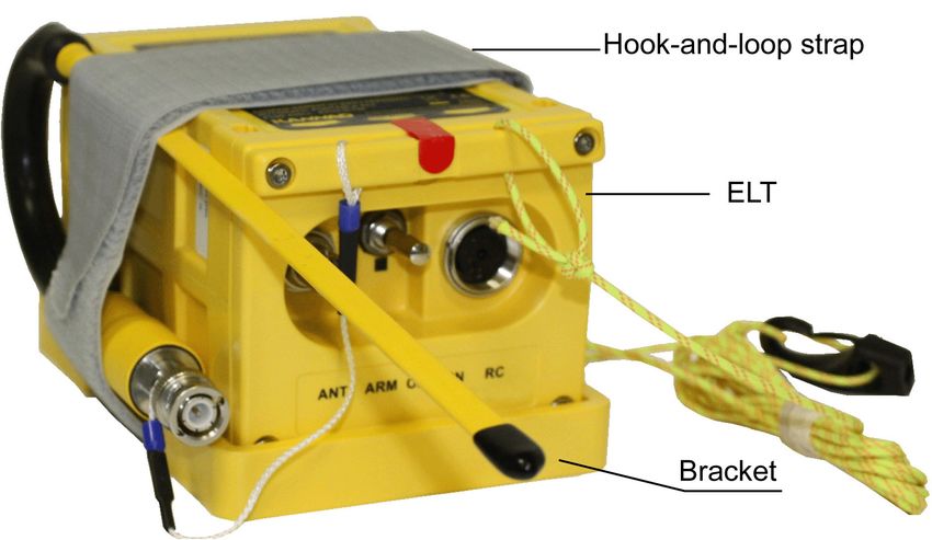
Users are kindly requested to notify Orolia S.A.S of any
           discrepancy, omission or error found in this manual.
                  Please report to our customer support:
                       E-mail: support@orolia.com
                         Tel.: +33 (0)2 97 02 49 00

This document is copyright © 2021 OROLIA S.A.S. All rights are strictly
reserved. This document and any attached materials contains proprietary
and confidential information and data and is the sole property of Orolia®
group and/or its affiliates.
The documents, any attached materials and/or information contained the-
rein must not be used, disseminated, or distributed except for the agreed
purpose. unauthorized use, reproduction, or issue to any third party is not
permitted without the prior written consent of the orolia group. This docu-
ment is to be returned to the orolia group when the agreed purpose is ful-
filled.

© 2021 Orolia S.A.S. All rigths are strictly reserved.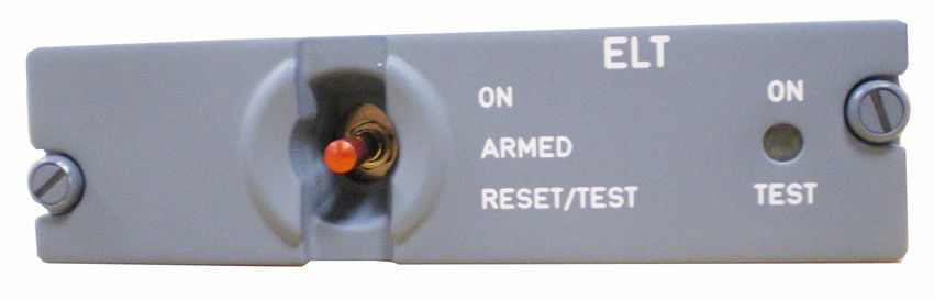
INITIAL INSTALLATION MANUAL
                                                              AP INTEGRA / AP-H INTEGRA

                                           TABLE OF CONTENTS

      Introduction ............................................................................................ 1
      INTEGRA ELT System Presentation ..................................................... 1
        System overview .................................................................................................... 1
        Transmitter and bracket.......................................................................................... 3
         ELT with hook-and-loop Mounting Bracket .......................................................... 4
         ELT with draw latch Mounting Bracket................................................................. 5
        Remote Control Panels (RCP)................................................................................ 6
         RC100 KIT ........................................................................................................... 6
         RC102 KIT ........................................................................................................... 6
         RC200 .................................................................................................................. 7
         RC300 / RC300 NVG ........................................................................................... 7
         RC310 .................................................................................................................. 8
         RC600 NVG ......................................................................................................... 8
         RC800 / RC810.................................................................................................... 8
        External antennas................................................................................................... 9
      Registration .......................................................................................... 10
        General ................................................................................................................. 10
        Registration in USA .............................................................................................. 10
        Registration in Canada ......................................................................................... 11
      ELT Installation .................................................................................... 12
        ELT and bracket installation recommendations.................................................... 12
         FAA Recommendations ..................................................................................... 12
         TSO-C126a Section 5 b. Application Data Requirements ................................. 12
         TSO-C126b Section a (3), Application Data Requirements ............................... 12
         RTCA DO-182 Recommandations..................................................................... 12
         RTCA DO-204a Requirements .......................................................................... 12
        ELT location recommendations ............................................................................ 13
        Bracket installation procedure .............................................................................. 14
         Determine location and direction........................................................................ 14
         Fix the mounting bracket.................................................................................... 16
        ELT installation procedure .................................................................................... 18
         Installation with hook-and-loop mounting brackets ............................................ 18
         ELT Installation with draw latch mounting bracket P/N S1850551-01 ............... 20
         ELT Installation with draw latch mounting bracket P/N S1850551-03 ............... 22
      Antenna Installation.............................................................................. 24
        Antenna Installation Recommendations ............................................................... 24
         FAA Recommendations ..................................................................................... 24
         RTCA DO-204 Recommendations for external antenna location ...................... 24
         External Antenna Location ................................................................................. 24
        Antenna installation procedure ............................................................................. 25

                                                                                                                       TOC PAGE: 1
© 2021 Orolia S.A.S. All rigths are strictly reserved.
                                                                                                                      SEPT 03/2021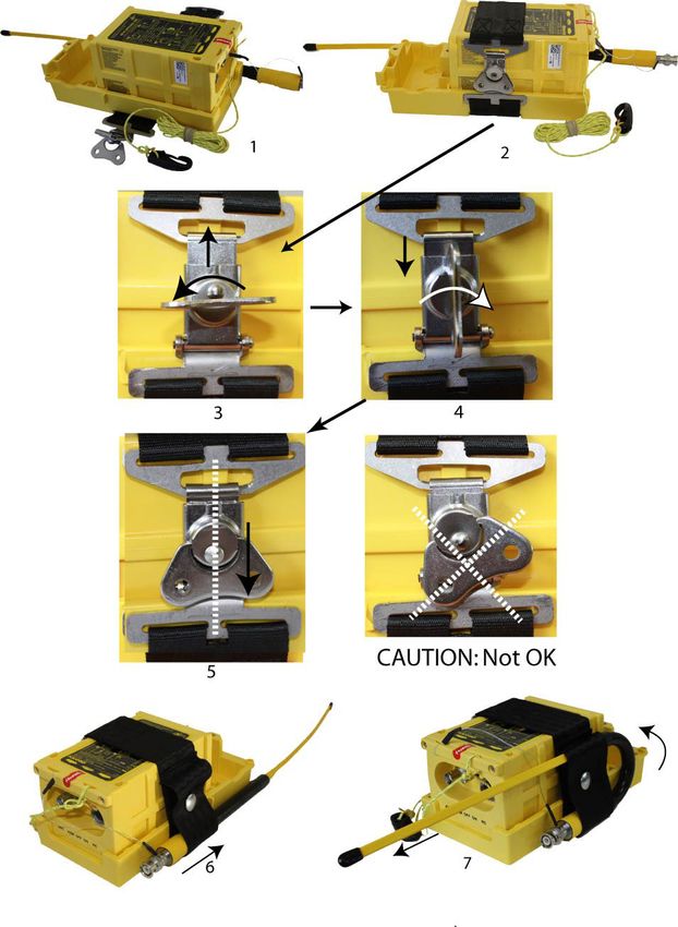
INITIAL INSTALLATION MANUAL
                                                            AP INTEGRA / AP-H INTEGRA

                                          TABLE OF CONTENTS

      RCP installation ................................................................................... 27
        RCP Installation Recommendations..................................................................... 27
        RCP Installation Procedure .................................................................................. 27
         DIN-12 connector, programming dongles other than AIRBUS dongles............. 27
         AIRBUS Programming dongles ......................................................................... 28
         RC100................................................................................................................ 29
         RC102................................................................................................................ 31
         RC200................................................................................................................ 34
         RC300 / RC300-NVG......................................................................................... 36
         RC310................................................................................................................ 37
         RC600 NVG ....................................................................................................... 38
         RC800................................................................................................................ 39
         RC810................................................................................................................ 39
      Outside Buzzer Installation .................................................................. 39
      ELT Connection ................................................................................... 40
      First power up procedure ..................................................................... 41
        ELT operational tests ........................................................................................... 41
        RCP operational tests .......................................................................................... 42
        406 and 121.5 MHz transmission test .................................................................. 43
         406 MHz ............................................................................................................ 43
         121.5 MHz ......................................................................................................... 44
      Outline dimensions and weights .......................................................... 45
      Wiring diagrams ................................................................................... 66
      Compatibility list for INTEGRA AP ELTs System................................. 79
        Mounting brackets ................................................................................................ 79
        Remote control panels (RCP) .............................................................................. 79
        DIN-12 connector or programming dongles ......................................................... 80
        Outside buzzer ..................................................................................................... 80
        External antennas ................................................................................................ 80

                                                                                                                    TOC PAGE: 2
© 2021 Orolia S.A.S. All rigths are strictly reserved.
                                                                                                                   SEPT 03/2021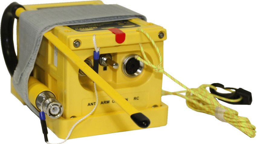
INITIAL INSTALLATION MANUAL
                                                           AP INTEGRA / AP-H INTEGRA

   1. Introduction
   The instructions in this manual provide the information necessary for the initial
   installation of AP INTEGRA / AP-H INTEGRA ELT system.

   2. INTEGRA ELT System Presentation
   A. System overview
   NOTE: for details of approved part number of AP INTEGRA / AP-H INTEGRA
   system, Refer to Section 12. Compatibility list for INTEGRA AP ELTs System,
   page 79.
   AP INTEGRA / AP-H INTEGRA system is composed of:
      1.      a transmitter;
      2.      a mounting bracket;
      3.      an approved external whip, rod or blade antenna;
      4.      an auxiliary antenna;
      5.      a remote control panel (RCP)(see NOTE 1);
      6.      a DIN-12 connector or programming dongle to connect the RCP or a
              Dongle IF GPS RS232(see NOTE 2) to connect the RCP and an onboard
              RS232 GPS;
      7.      an outside buzzer.
   The most effective external antenna configuration is on top of the fuselage, aft
   of the wing or near the vertical stabilizer. The ELT and mounting bracket should
   be mounted in the aircraft as close to the antenna as practicable with a coaxial
   cable towards the antenna as short as possible. The remote control panel(1) is
   installed in the cockpit and connected to the ELT with a 2, 3, 4, 5-wire bundle
   (not supplied) according to the type of Remote Control Panel.
   NOTE: (1) The RCP is optional only if the commands and controls of
          the ELT are reachable and visible from the pilot seated position.
          (RTCA DO-204A): “Equipment control and indicator installed for in-
          flight use shall be readily accessible from the cockpit crew position.
          The cockpit crew shall have an unobstructed view of visual indicator
          when in the normal seated position.”
   NOTE: (2) GPS/NAV Interface with an onboard RS232 GPS.

                                                                                           PAGE: 1
© 2021 Orolia S.A.S. All rigths are strictly reserved.
                                                                                       SEPT 03/2021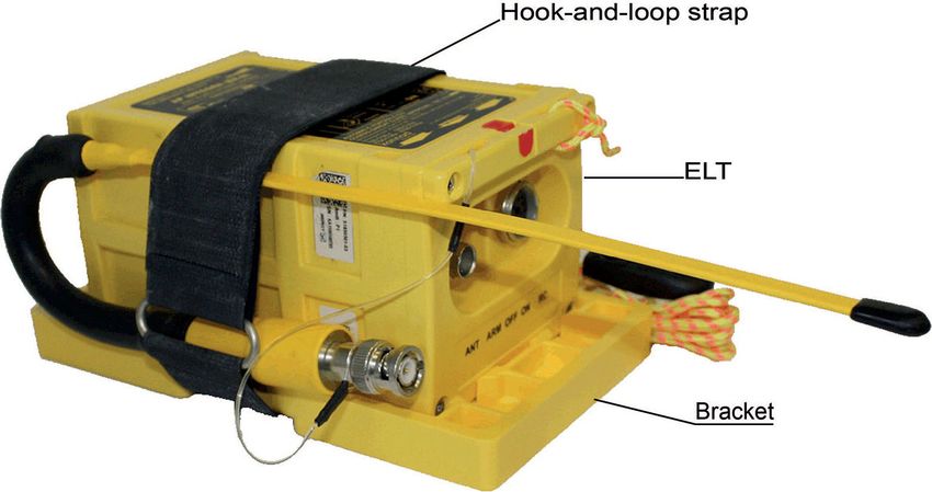
INITIAL INSTALLATION MANUAL
                                                           AP INTEGRA / AP-H INTEGRA

                              Figure 1: ELT Standard System Description

                Figure 2: ELT System with Dongle IF GPS RS232 Description

                                                                                           PAGE: 2
© 2021 Orolia S.A.S. All rigths are strictly reserved.
                                                                                       SEPT 03/2021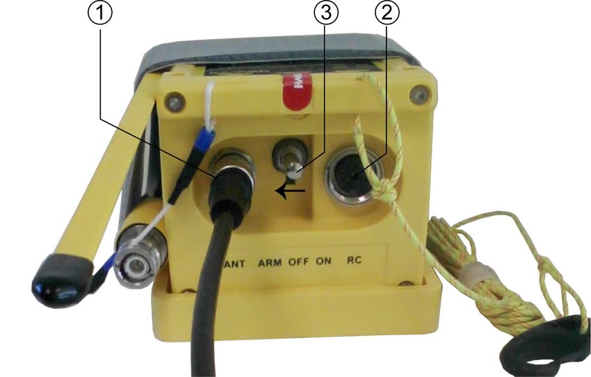
INITIAL INSTALLATION MANUAL
                                                           AP INTEGRA / AP-H INTEGRA

   B. Transmitter and bracket
   The ELT must be installed into one of the approved mounting brackets. The
   mounting bracket preferably installed near the tail is designed to secure the
   ELT with a strap. This enables quick removal of the ELT for maintenance,
   exchange or in case of emergency use (use of the ELT in portable configuration
   with the auxiliary antenna).
   Mounting brackets with hook-and-loop (Velcro®) strap are ETSO-2C126 /
   TSO-C126a approved.
   Mounting brackets with draw latch strap (non-hook-and-loop) are ETSO-126a
   / TSO-C126b approved.
   Drilling holes of Universal Mounting Bracket are compatible with former
   mounting brackets to re-use existing drilling for retrofit.
   All mounting brackets are designed to allow the fastening mechanism to be
   placed either to the left or to the right of the ELT.

   IMPORTANT: Orolia S.A.S. recommends the use of TSO-C126b approved
   mounting bracket.
   Installation of INTEGRA and INTEGRA (ER) ELT with hook-and-loop
   mounting brackets invalidates the TSO-C126b.
   The summary of compatible mounting brackets is as follows:

   P/N                     Designation                                 Strap           Approval
   S1840502-01 COMPACT Mounting Bracket                                Hook-and-loop TSO-C126a
   S1840502-02 COMPACT Universal Mounting                              Hook-and-loop TSO-C126a
               Bracket
   S1850551-03 Mounting Bracket INTEGRA AP Draw latch                                  TSO-C126b
   S1850551-01 Bracket Universal for INTEGRA                           Draw latch      TSO-C126b
               ARINC e-NAV for ELT (AP)

   Refer to Section 12. Compatibility list for INTEGRA AP ELTs System, page 79
   for Part Numbers of approved mounting brackets.

                                                                                           PAGE: 3
© 2021 Orolia S.A.S. All rigths are strictly reserved.
                                                                                       SEPT 03/2021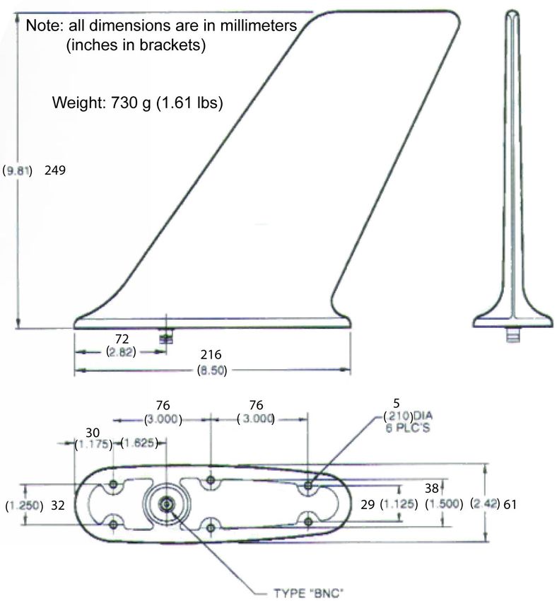
INITIAL INSTALLATION MANUAL
                                                           AP INTEGRA / AP-H INTEGRA

      (1) ELT with hook-and-loop Mounting Bracket
            Figure 3: INTEGRA ELT with Mounting Bracket P/N S1840502-01

            Figure 4: INTEGRA ELT with Mounting Bracket P/N S1840502-02

                                                                                           PAGE: 4
© 2021 Orolia S.A.S. All rigths are strictly reserved.
                                                                                       SEPT 03/2021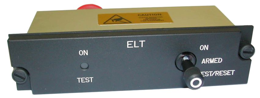
INITIAL INSTALLATION MANUAL
                                                           AP INTEGRA / AP-H INTEGRA

      (2) ELT with draw latch Mounting Bracket
            Figure 5: INTEGRA ELT with Mounting Bracket P/N S1850551-03

                    Figure 6: INTEGRA ELT with Bracket P/N S1850551-01

                                                                                           PAGE: 5
© 2021 Orolia S.A.S. All rigths are strictly reserved.
                                                                                       SEPT 03/2021
INITIAL INSTALLATION MANUAL
                                                           AP INTEGRA / AP-H INTEGRA

   C. Remote Control Panels (RCP)
   Refer to Section 12. Compatibility list for INTEGRA AP ELTs System, page 79
   for Part Numbers of approved RCPs.
   The RCP must be installed in the cockpit to monitor and control the ELT status.
   It must be connected via a 2, 3, or 4-wire bundle to the DIN-12 socket of the
   ELT (2, 3, 4-wire bundle is not supplied)
   NOTE: An optional outside buzzer assembly can be connected to the ELT-
         RCP. It gives an audio indication of emergency location transmitter
         (ELT) activation. It is supplied with a mounting tray to install the
         buzzer on the aircraft.
                                             Figure 7: Outside buzzer

      (1)RC100 KIT
          The RC100 remote control panel is connected to the ELT via a 3-wire
          cable equipped with a DIN-12 connector or optional programming dongle
          on the ELT side and directly connected to the RCP on the other side.
                                 Figure 8: RC100 Remote Control Panel

      (2) RC102 KIT
          The RC102 remote control panel is connected to the ELT via a 2-wire
          cable equipped with a DIN-12 connector or optional programming dongle
          on the ELT side and directly connected to the RCP on the other side. 2
          types of front panels are supplied in the kit. The appropriate front panel
          should be choosen according to the place available on the aircraft’s
          instrument panel.

                                                                                           PAGE: 6
© 2021 Orolia S.A.S. All rigths are strictly reserved.
                                                                                       SEPT 03/2021
INITIAL INSTALLATION MANUAL
AP INTEGRA / AP-H INTEGRA
NOTE: the optional outside buzzer is not available with this RCP.
Figure 9: RC102 Remote Control Panel
(3) RC200
The RC200 or RC200 NVG remote control panel is connected to the ELT
via a 3 or 4-wire bundle equipped with a DIN-12 connector or optional
programming dongle on the ELT side and a D-SUB Female 9 pins
connector on the other side.
Figure 10: RC200 Remote Control Panel
(4) RC300 / RC300 NVG
The RC300 is connected to the ELT via a 4 -wire bundle equipped with a
DIN-12 connector or optional programming dongle on the ELT side and a
D-SUB 9 PTS Male connector on the other side.
Figure 11: RC300 Remote Control Panel
PAGE: 7
© 2021 Orolia S.A.S. All rigths are strictly reserved.
SEPT 03/2021INITIAL INSTALLATION MANUAL
AP INTEGRA / AP-H INTEGRA
(5) RC310
The RC310 is connected to the ELT via a 4-wire bundle equipped with a
DIN-12 connector or optional programming dongle on the ELT side and a
D-SUB 9 pins Female connector on the other side
Figure 12: RC310 Remote Control Panel
(6) RC600 NVG
The RC600 NVG is connected to the ELT via a 5-wire bundle equipped
with a DIN-12 connector or optional programming dongle on the ELT side
and a female 22-pin connector on the other side.
Figure 13: RC600 NVG Remote Control Panel
IMPORTANT NOTICE: Non ETSO equipment only designed to be
installed on military aircraft.
(7) RC800 / RC810
RC800 and RC810 are connected to the ELT via a 4 or 5-wire bundle
equipped with a DIN-12 connector or optional programming dongle on the
ELT side and a Jaeger female 19-pin connector on the other side
Figure 14: RC800 / 810 Remote Control Panels
PAGE: 8
© 2021 Orolia S.A.S. All rigths are strictly reserved.
SEPT 03/2021INITIAL INSTALLATION MANUAL
AP INTEGRA / AP-H INTEGRA
D. External antennas
The external antenna can be either of whip, rod or blade type according to
aircraft speed.
Connection to the ELT will be carried out with a 50 Ohm coaxial cable ended
with two male BNC connectors.
IMPORTANT NOTICE: Orolia S.A.S. recommends a cable with radio
electric properties similar or better to those of a RG58 cable.
NOTE: the 50 Ohm coaxial cable and the male BNC connectors are not
supplied.
Figure 15: Whip, rod and blade antennas
Whip antenna type
Rod antenna type
Blade antenna type
PAGE: 9
© 2021 Orolia S.A.S. All rigths are strictly reserved.
SEPT 03/2021INITIAL INSTALLATION MANUAL
AP INTEGRA / AP-H INTEGRA
3. Registration
A. General
The ELT must be registered prior to installation on board.
When a 406 MHz ELT is installed in an aircraft, it is imperative that the aircraft
owner register the ELT. Each 406 MHz ELT contains a unique identification
code that is transmitted to the satellite. This helps the “Rescue Coordination
Center” (RCC) determine whether an emergency has actually occurred. The
unique identification permits accessing a data base.
The registration card available from the local registration authority must be
completed and returned to this authority.
Any change of ownership shall also be declared and registered with the local
registration authority.
B. Registration in USA
Mail or Fax your registration form to:
SARSAT BEACON REGISTRATION
NOAA
NSOF, E/SPO53
1315 East West Hwy
Silver Spring, MD 20910
or Save Time! Register your beacon online at:
www.beaconregistration.noaa.gov
All online registrations will be entered into the National 406 MHz Beacon
Registration Database on the same day of entry. Registration forms received
via postal mail will be entered within 2 business days of receipt. For online
registrations, a confirmation letter with your completed registration information
form will be sent immediately via e-mail or fax (if provided). Confirmation letters
sent via postal mail should arrive within two weeks. Once your registration
confirmation is received, please review all information. Any changes or updates
to your registration information can be done via the internet, fax, e-mail or
postal mail. If you do not receive your registration confirmation from NOAA on
the same day you submit it over the internet or within two weeks if you submit
it by postal mail, please call NOAA toll-free at: 1-888-212-SAVE (7283) or
301-817-4515 for assistance.
After initial registration (or re-registration) you will receive a NOAA Proof of
Registration Decal by postal mail. This decal is to be affixed to the beacon and
should be placed in such a way that it is clearly visible. If for some reason you
do not receive the registration decal within two weeks, please call NOAA
PAGE: 10
© 2021 Orolia S.A.S. All rigths are strictly reserved.
SEPT 03/2021INITIAL INSTALLATION MANUAL
AP INTEGRA / AP-H INTEGRA
toll-free at: 1-888-212-SAVE (7283) or 301-817-4515.
Failure to register, re-register (as required every two years), or to notify NOAA
of any changes to the status of your 406 MHz beacon could result in penalties
and/or fines being issued under Federal Law. The owner or user of the beacon
is required to notify NOAA of any changes to the registration information at any
time. By submitting this registration the owner, operator, or legally authorized
agent declares under penalty of law that all information in the registration
information is true, accurate, and complete. Providing information that is
knowingly false or inaccurate may be punishable under Federal Statutes.
Solicitation of this information is authorized by Title 47 - Parts 80, 87, and 95 of
the U.S. Code of Federal Regulations (CFR). Additional registration forms can
be found on the NOAA-SARSAT website at:
www.sarsat.noaa.gov or at: www.beaconregistration.noaa.gov
C. Registration in Canada
Beacon information is held in the Canadian Beacon Registry maintained by the
National Search and Rescue Secretariat for use in search and rescue
operations. Online access to the Registry is available for all beacon owners to
register new beacons or to update their beacon information. You can add or
update your beacon information by accessing the registry directly, sending in a
completed registration form or by talking to one of our beacon registry
representatives.
You can access the registry:
• online: www.canadianbeaconregistry.com
• by email: CBR@Sarnet.dnd.ca
• by fax: 1-613-996-3746
• by telephone: 1-800-727-9414 or 1-613-996-1616
The registration information must be updated when the aircraft ownership
changes as per the Canadian Airworthiness Notice AN B029 (refer to following
link):
http://www.nss.gc.ca/site/Emergency_Beacons/canadian_beacon_registry_e.asp
Additional information and registration forms can be found on the Canadian
NSS website at:
http://www.nss.gc.ca/site/cospas-sarsat/INTRO_e.asp
PAGE: 11
© 2021 Orolia S.A.S. All rigths are strictly reserved.
SEPT 03/2021INITIAL INSTALLATION MANUAL
AP INTEGRA / AP-H INTEGRA
4. ELT Installation
A. ELT and bracket installation recommendations
The ELT shall not be installed within 30cm (1 ft) of a compass or flux gate.
The distance between ELT and antenna shall be determined according to the
coaxial cable choosen.
The ELT front panel should be easily accessible to connect the external
antenna and the remote control panel device and to check the ELT good
operation (controls and lights).
(1)FAA Recommendations
Installation must be made by qualified personnel in accordance with FAA
regulations. Duplicating a previous installation may not be acceptable.
Refer to:
FAA - Advisory Circular 43.13-2B (Acceptable Methods, Techniques,
and Practices - Aircraft Alterations), specifically, Chapters 1, 2, 11
and 13.
(2) TSO-C126a Section 5 b. Application Data Requirements
“The conditions and tests for TSO approval of this article are minimum
performance standards. Those installing this article, on or in a specific type
or class of aircraft, must determine that the aircraft installation conditions
are within the TSO standards. TSO articles must have separate approval
for installation in an aircaft. The article may be installed only according to
14 CFR part 43 of the applicable airworthiness requirements”.
(3) TSO-C126b Section a (3), Application Data Requirements
Limitations:
“This article meets the minimum performance and quality control
standards required by a technical standard order (TSO). Installation of this
article requires separate approval”.
(4) RTCA DO-182 Recommandations
“All ELT system components which must survive to a crash intact,...should
be attached to the airframe in such a manner that the attachment system
can support a 100g load... in the plus and minus directions of the three
principal axes of the aircraft.”
(5) RTCA DO-204a Requirements
“The ELT unit shall be mounted to primary aircraft load-carrying structures
such as trusses, bulkheads, longerons, spars or floor beams (not aircraft
skin) or a structure that meets the requirements of the following test. The
mounts shall have a maximum static local deflection no greater than 2.5
PAGE: 12
© 2021 Orolia S.A.S. All rigths are strictly reserved.
SEPT 03/2021INITIAL INSTALLATION MANUAL
AP INTEGRA / AP-H INTEGRA
mm when a force of 450 Newtons (l00 lbf) is applied to the mount in the
most flexible direction. Deflection measurements shall be made with
reference to another part of the airframe not less than 0.3 m or more than
1.0 m from the mounting location. Typical approaches for adding shelf
and rail platform mounting provisions to aircraft structure as shown an
FAA Advisory circular 43.13-2(), Chapter 2."
B. ELT location recommendations
Orolia S.A.S. provides additional safety functions in the INTEGRA ELTs such
as built-in GPS and built-in back-up antenna.
If the link towards the external antenna is defective, the built-in back-up
antenna, protected by the high resistance housing of the ELT, may help to
establish a link towards the satellites Cospas-Sarsat system.
However, Orolia S.A.S. cannot control neither the environment of the ELT when
a crash occurs nor a too important metallic structure around the ELT. For these
reasons, Orolia S.A.S. recommends to install the ELT in a location in such a
way that the vertical extension of the built-in back-up antenna is exposed to a
RF transparent window.
PAGE: 13
© 2021 Orolia S.A.S. All rigths are strictly reserved.
SEPT 03/2021INITIAL INSTALLATION MANUAL
AP INTEGRA / AP-H INTEGRA
C. Bracket installation procedure
(1)Determine location and direction
Figure 16: AP INTEGRA, axis of installation
- Determine the location of the ELT on board according to paragraph A.
ELT and bracket installation recommendations page 12.
- The G-Switch axis shall be directed to sense the primary crash pulse
along the longitudinal axis of the aircraft. Reference to the G-Switch is
given by the arrow “Flight direction” on the label affixed to the top of the
ELT.
(a) Fixed wing aircraft with AP INTEGRA
Refer to Figure 16: AP INTEGRA, axis of installation.
The G-Switch sensor axis shall be pointed to sense the primary crash
pulse along the longitudinal axis of the aircraft (with maximum tolerance of
± 2°). Consequently, the AP INTEGRA shall be mounted:
- with the arrow of the “Flight direction” label pointed towards the front of
the aircraft;
PAGE: 14
© 2021 Orolia S.A.S. All rigths are strictly reserved.
SEPT 03/2021INITIAL INSTALLATION MANUAL
AP INTEGRA / AP-H INTEGRA
- in any position parallel to the roll axis.
(b) Helicopters with AP INTEGRA
Refer to Figure 16: AP INTEGRA, axis of installation.
AP-INTEGRA may be installed on helicopter. The ELT unit should be
mounted (with maximum tolerance of ±2°):
• with "Flight direction" arrow towards the front of the helicopter;
• with the front face connectors pointing downwards at a 45° angle to
the yaw axis;
• in any position parallel to the 45° axis.
(c) Helicopters with AP-H INTEGRA
Refer to Figure 17: AP-H INTEGRA, axis of installation.
IMPORTANT: AP-H INTEGRA is designed to be mounted on board
helicopters only.
Figure 17: AP-H INTEGRA, axis of installation
The "Direction of Flight " arrow shall point towards the front or the bottom
of the helicopter (and not pointing 45° downwards):
- If the AP-H INTEGRA is installed with the “Direction of Flight” arrow
pointing towards the front of the helicopter, the ELT shall be mounted
with the upper side pointing towards the top of the helicopter.
- If the AP-H INTEGRA is installed with the “Direction of Flight” arrow
pointing towards the bottom of the helicopter, the ELT shall be installed
with the lower side pointing towards the front of the helicopter
PAGE: 15
© 2021 Orolia S.A.S. All rigths are strictly reserved.
SEPT 03/2021INITIAL INSTALLATION MANUAL
AP INTEGRA / AP-H INTEGRA
(2) Fix the mounting bracket
- Drill 4 holes Ø 6 mm in the aircraft structure: refer to either Figure 39:
Compact Mounting bracket P/N S1840502-01, Outline dimensions and
weight page 49 [Inner holes (1, 2, 3, 4) should be preferred] or Figure
40: Compact Universal Mounting bracket P/N S1840502-02, Outline
dimensions and weight page 50 or Figure 41: Bracket Universal for
INTEGRA ARINC e-NAV for ELT (AP) P/N S1850551-01, Outline
Dimensions and Weight page 51 or Figure 42: Mounting Bracket
INTEGRA AP P/N S1850551-03, Outline Dimensions and Weight page
52 according to mounting bracket used.
- If the attachment system is not solid enough to withstand a 100G load
([ELT + bracket weight] x 100) on the bracket, a reinforcement plate (not
supplied) should be installed as shown Figure 19: Bracket installation in
order to be compliant with the RTCA DO-182 recommendation.
- Place the strap onto the back side of the mounting bracket. Make sure
to place the fastening mechanism at the most convenient side of the
ELT, either left or right.
- For Bracket Universal for INTEGRA ARINC e-NAV for ELT (AP),
P/N S1850551-01, place the draw latch strap onto the back side of the
mounting bracket. Engage the hole of the strap onto the indexing slot of
the mounting bracket (Refer to Figure 18: Strap Installation on Bracket
P/N S1850551-01 below).
Figure 18: Strap Installation on Bracket P/N S1850551-01
- Fix the bracket with the 4 screws, 8 washers and 4 nylstop nuts supplied.
IMPORTANT: tighten to a torque between 4 and 5 Newton x meter.
PAGE: 16
© 2021 Orolia S.A.S. All rigths are strictly reserved.
SEPT 03/2021INITIAL INSTALLATION MANUAL
AP INTEGRA / AP-H INTEGRA
Figure 19: Bracket installation
PAGE: 17
© 2021 Orolia S.A.S. All rigths are strictly reserved.
SEPT 03/2021INITIAL INSTALLATION MANUAL
AP INTEGRA / AP-H INTEGRA
D. ELT installation procedure
(1)Installation with hook-and-loop mounting brackets
Refer to Figure 20: ELT installation with hook-and-loop Mounting Bracket, page
19
1. Mount the transmitter on the bracket
• For AP INTEGRA or AP INTEGRA (ER), with "Flight Direction Arrow"
of the ELT pointed towards the front of the aircraft, according to Figure
16: AP INTEGRA, axis of installation page 14.
• For AP-H INTEGRA or AP-H INTEGRA (ER), with "Flight Direction
Arrow" of the ELT pointed towards the front or downwards the
helicopter according to Figure 17: AP-H INTEGRA, axis of installation
page 15.
2. Slide the strap through the buckle. Ensure the buckle is correctly
positioned (indifferently on right or left side of ELT) regarding the
horizontal center line of ELT as shown Detail A.
3. Fold the antenna and slide it under the strap.
4. Fasten the strap tightly.
IMPORTANT: Once installed in the mounting bracket, the installer
must make sure that the transmitter is firmly attached in its bracket
by trying to extract it manually, thereby verifying there is no play
and that it remains attached when extraction from the bracket is
attempted.
CAUTION:
AN INCORRECT TIGHTENING OF THE HOOK AND LOOP
FASTENER COULD LEAD TO AN UNSAFE SITUATION BY THE ELT
PREVENTING THE TRANSMISSION OF THE DISTRESS MESSAGE
PAGE: 18
© 2021 Orolia S.A.S. All rigths are strictly reserved.
SEPT 03/2021INITIAL INSTALLATION MANUAL
AP INTEGRA / AP-H INTEGRA
Figure 20: ELT installation with hook-and-loop Mounting Bracket
PAGE: 19
© 2021 Orolia S.A.S. All rigths are strictly reserved.
SEPT 03/2021INITIAL INSTALLATION MANUAL
AP INTEGRA / AP-H INTEGRA
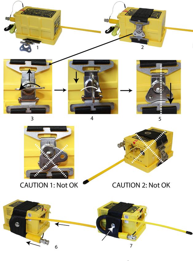
(2) ELT Installation with draw latch mounting bracket P/N S1850551-01
Refer to Figure 21: ELT Installation with Bracket Universal for INTEGRA
ARINC e-NAV for ELT (AP) P/N S1850551-01 page 21
1. Place the INTEGRA ELT onto the Bracket with “Flight Direction Arrow”
of the ELT pointed towards the front of the aircraft.
• For AP INTEGRA, refer to Figure 16: AP INTEGRA, axis of installation
page 14.
• For AP-H INTEGRA refer to Figure 17: AP-H INTEGRA, axis of
installation page 15.
2. Pass the strap with the buckle above the ELT.
3. Do a quarter turn counterclockwise to the latch then bring the hook of
the latch onto the buckle of the strap.
4. Do a quarter turn clockwise to the latch to fix the strap by sliding the hook
down.
5. Pull down the latch to lock the strap.
CAUTION:
WHEN LOCKED, THE CENTER OF THE LATCH SHALL BE
ALIGNED WITH THE CENTER OF THE BUCKLE (Refer to Figure 21:
ELT Installation with Bracket Universal for INTEGRA ARINC e-NAV
for ELT (AP) P/N S1850551-01 page 21, picture 5).
Check that the ELT is firmly attached:
IMPORTANT: Once installed in the mounting bracket, the installer
must make sure that the transmitter is firmly attached in its bracket
by trying to extract it manually, thereby verifying there is no play
and that it remains attached when extraction from the bracket is
attempted.
CAUTION:
AN INCORRECT LOCKING OF THE LATCH COULD LEAD TO AN
UNSAFE SITUATION BY THE ELT PREVENTING THE
TRANSMISSION OF THE DISTRESS MESSAGE.
6. Slide the auxiliary antenna (extremity first) into the lower antenna
housing of the strap. Only the BNC connector shall be visible from this
antenna housing.
7. Bend the antenna, then slide the extremity of the antenna into the upper
antenna housing of the strap.
PAGE: 20
© 2021 Orolia S.A.S. All rigths are strictly reserved.
SEPT 03/2021INITIAL INSTALLATION MANUAL
AP INTEGRA / AP-H INTEGRA
Figure 21: ELT Installation with Bracket Universal for INTEGRA ARINC e-NAV
for ELT (AP) P/N S1850551-01
PAGE: 21
© 2021 Orolia S.A.S. All rigths are strictly reserved.
SEPT 03/2021INITIAL INSTALLATION MANUAL
AP INTEGRA / AP-H INTEGRA
(3) ELT Installation with draw latch mounting bracket P/N S1850551-03
Refer to: Figure 22: ELT installation with Mounting Bracket INTEGRA AP
P/N S1850551-03
1. Place the INTEGRA ELT onto the Bracket with “Flight Direction Arrow”
of the ELT pointed towards the front of the aircraft.
• For AP INTEGRA, refer to Figure 16: AP INTEGRA, axis of installation
page 14.
• For AP-H INTEGRA refer to Figure 17: AP-H INTEGRA, axis of
installation page 15.
2. Pass the strap with the buckle above the ELT.
3. Do a quarter turn counterclockwise to the latch then bring the hook of
the latch onto the buckle of the strap.
4. Do a quarter turn clockwise to the latch to fix the strap by sliding the hook
down.
5. Pull down the latch to lock the strap.
CAUTION 1: WHEN LOCKED, THE CENTER OF THE LATCH SHALL
BE ALIGNED WITH THE CENTER OF THE BUCKLE (Refer to Figure
22: ELT installation with Mounting Bracket INTEGRA AP P/N
S1850551-03 page 23, picture 5).
CAUTION 2: NEVER INSTALL THE STRAP WITH THE GROMMET
ON TOP OF THE ELT, THIS WOULD PREVENT THE RADIATION OF
THE BUILT-IN BACK-UP ANTENNA AND RECEPTION OF GPS
SIGNAL.
Check that the ELT is firmly attached:
IMPORTANT: Once installed in the mounting bracket, the installer
must make sure that the transmitter is firmly attached in its bracket
by trying to extract it manually, thereby verifying there is no play
and that it remains attached when extraction from the bracket is
attempted.
CAUTION:
AN INCORRECT LOCKING OF THE LATCH COULD LEAD TO AN
UNSAFE SITUATION BY THE ELT PREVENTING THE
TRANSMISSION OF THE DISTRESS MESSAGE.
6. Bend and slide the auxiliary antenna into the antenna housing of the
strap.
7. The antenna is in a correct position when its rear black part is at the
same level than the rear of the ELT. Firmly press the pushbutton of the
PAGE: 22
© 2021 Orolia S.A.S. All rigths are strictly reserved.
SEPT 03/2021INITIAL INSTALLATION MANUAL
AP INTEGRA / AP-H INTEGRA
strap to lock the auxiliary antenna in the antenna housing.
Figure 22: ELT installation with Mounting Bracket INTEGRA AP
P/N S1850551-03
PAGE: 23
© 2021 Orolia S.A.S. All rigths are strictly reserved.
SEPT 03/2021INITIAL INSTALLATION MANUAL
AP INTEGRA / AP-H INTEGRA
5. Antenna Installation
Use only whip, rod or blade approved antennas.
A. Antenna Installation Recommendations
(1)FAA Recommendations
Installation must be made by qualified personnel in accordance with FAA
regulations. Duplicating a previous installation may not be acceptable.
Methods for installing antenna are outlined in AC43.13-12, refer to:
FAA - Advisory Circular 43.13-2B (Acceptable Methods, Techniques,
and Practices - Aircraft Alterations), specifically, Chapters 1, 3, 11
and 13.
(2) RTCA DO-204 Recommendations for external antenna location
“ELT antennas should be located away from other antennas to avoid
disruption of antenna radiation patterns.”
“Idealistically, for the 121.5 MHz ELT antenna, 2.5 meter separation is
sufficient separation from VHF communications and navigation receiving
antennas to minimize unwanted interferences.”
“ELT antennas should be vertically polarized when the aircraft is in the
normal flight attitude.”
“ELT antenna mounting surface should be able to withstand a static load
equal to 100 times the antenna weight applied at the antenna mounting
base in all directions.”
“The antenna should be mounted as close to the respective ELT as
applicable. The proximity of the ELT antenna to any vertically-polarized
communications antenna shall be such as to minimize radio frequency
interference and radiation pattern distortion of either antenna. Coaxial
cable connecting the ELT antenna installation should not cross the aircraft
production breaks and should have vibrations proof RF connectors on
each end. The coaxial connecting the ELT transmitter to the external
Antenna should be secured to the aircraft structure and when the coaxial
cable is installed and the connectors are mated, each end should be have
some slack.”
(3) External Antenna Location
EUROCAE ED62A § 6.1.10.2
“The most effective antenna configuration for typical high-wing and low-
wing aircraft is an external antenna, on top of the fuselage, and aft of the
wing (high-wing), or near the vertical stabilizer (low-wing). Both ELT
antennas should be located away from other antennas to avoid disruption
PAGE: 24
© 2021 Orolia S.A.S. All rigths are strictly reserved.
SEPT 03/2021INITIAL INSTALLATION MANUAL
AP INTEGRA / AP-H INTEGRA
of antenna radiation patterns. Detuning of the 121.5 MHz antenna may be
required avoid the effects of radiated inter-modulation products which may
be possible from non-operating 121.5 MHz ELTs exposed to high levels of
RF energy.
Idealistically, for the 121.5 MHz ELT antenna, 2.5 meter separation is
sufficient separation from VHF communications and navigation receiving
antennas to minimize unwanted interference. The 406 MHz ELT antenna
should be positioned at least 0.8 m from VHF communications and
navigation receiving antennas to minimize interference.
External antennas, which have been shown to be compatible with
particular ELT will either be part of the ETSO/TSO'd ELT or will be
identified in the ELT manufacturer's installation instructions.
Recommended methods for installing antenna are outlined in FAA AC
43.13-2B. The Antenna should be mounted as close to the respective ELT
as practicable.”
B. Antenna installation procedure
The antenna must be mounted on the top of the aircraft to assure maximum
visibility of satellites. The upper aft portion of the fuselage should be preferred.
It should be mounted away from projections such as a propeller, tail surfaces,
or the shadow of large antennas. It is the responsibility of the installation
agency to determine the appropriate and adequate antenna installation.
Locate a position on the fuselage according to Section (2) RTCA DO-204
Recommendations for external antenna location, page 24:
A double plate may be necessary for the antenna to meet rigidity specifications
in Section (2) RTCA DO-204 Recommendations for external antenna location,
page 24.
A 9 Kilogram force (20 pound force) applied in all direction should not cause an
appreciable distortion in the aircraft skin.
Each of the approved antennas requires a ground plane. On fabric-covered
aircraft or aircraft with other types on nonmetallic skins, a ground plane must
be added. This can be accomplished by providing a number of metal foil strips
in a radial position from the antenna base and secured under the fabric or wood
skin of the aircraft. The length of each foil radial should be at least equal to the
antenna length and width at least 1 inch due to the diameter of the antenna. The
ground plane must be connected to the shield of the antenna connector.
PAGE: 25
© 2021 Orolia S.A.S. All rigths are strictly reserved.
SEPT 03/2021INITIAL INSTALLATION MANUAL
AP INTEGRA / AP-H INTEGRA
See figure below:
Figure 23: Antenna ground plane for non metallic aircraft
According to the antenna to be installed, use the appropriate outline drawings
and drilling masks to determine the hole pattern and drill size refer to the
relevant antenna outline dimensions page 60, page 61, page 62.
Fabricate a 50 Ohms coaxial cable long enough to reach between the ELT
installation location and the antenna location.
IMPORTANT: The use of a low attenuation coaxial cable is recommended.
The maximum permitted attenuation in the coaxial is 2dB@400 MHz (See
IMPORTANT NOTICE, External antennas, page 9).
Fit both ends of coaxial cable with a waterproof Male BNC connector (not
supplied), reference RADIALL R141007 or equivalent.
Connect one Male BNC connector to the antenna Female BNC socket.
PAGE: 26
© 2021 Orolia S.A.S. All rigths are strictly reserved.
SEPT 03/2021INITIAL INSTALLATION MANUAL
AP INTEGRA / AP-H INTEGRA
6. RCP installation
A. RCP Installation Recommendations
The RCP shall be installed in the cockpit. The RCP shall be readily accessible
from the pilot’s normal seated position.
B. RCP Installation Procedure
(1)DIN-12 connector, programming dongles other than AIRBUS dongles
The RCP must be connected to the ELT via a DIN-12 connector (P/N
S1820514-03), a Programming Dongle or Dongle IF GPS RS232 (Refer to
Section 12. Compatibility list for INTEGRA AP ELTs System, page 79) on the
ELT side and the relevant mating connector of the RCP on the RCP side
(except for RC100 and RC102, wires directly connected to the RCP without
connectors).
Figure 24: Example of connection ELT to RCP
NOTE 1: in order to easily remove the programming dongle, when the RCP is
connected to the ELT via a Programming Dongle (P/N S1820514-01), it is
recommended to fit its cable with a stopping connector as close as possible to
it (see figure below).
Figure 25: Bundle with stopping connector
NOTE 2: The mounting of a stopping connector may be skipped by using our
pre-wired Programming Dongle ASSY (P/N S1820514-06). This dongle is fitted
with the Programming Dongle (S1820514-01) on the ELT side and a female
DIN-12 connector on the RCP side. In this case, a RCP bundle must be
fabricated using a male DIN-12 connector (reference P/N S1820514-03 or
BINDER 680-1-09-0329-00-12) and the relevant mating connector of the RCP.
PAGE: 27
© 2021 Orolia S.A.S. All rigths are strictly reserved.
SEPT 03/2021INITIAL INSTALLATION MANUAL
AP INTEGRA / AP-H INTEGRA
The Dongle IF GPS RS232 is also fitted with a male DIN-12 connector on the
ELT side and a female DIN-12 connector on the RCP side.
Figure 26: Programming Dongle ASSY / Dongle IF GPS RS232
(2) AIRBUS Programming dongles
Programming dongle INTEGRA / SA (P/N S1820514-11) and
Programming dongle INTEGRA / LR (P/N S1820514-07) are pre-wired
programming dongle specific for AIRBUS aircraft, they are fitted with:
- the programming dongle S1820514-01 on the ELT side and a Jaeger 19
connector on the RCP side for the programming dongle INTEGRA / SA,
The programming dongle INTEGRA / SA, P/N S1820514-11, is supplied
with its connection cable compliant with AIRBUS standard. No
supplementary connection cable has to be made.
- the programming dongle S1820514-01on the ELT side and an open-end
connector with five crimped male contacts on the RCP side for the
programming dongle INTEGRA / LR.
Figure 27: Programming dongle INTEGRA / SA
Figure 28: Programming dongle INTEGRA / LR
PAGE: 28
© 2021 Orolia S.A.S. All rigths are strictly reserved.
SEPT 03/2021INITIAL INSTALLATION MANUAL
AP INTEGRA / AP-H INTEGRA
(3) RC100
RC100 RCP is supplied as a kit (Refer to Figure 29: RC100 mounting
diagram).
Connection of RC100 requires a 3-wire bundle or 5-wire bundle if an
outside buzzer is connected. A pin-to-pin wiring has to be provided by the
installer with AWG24 wires. Shielded wires are recommended.
The wires are soldered to the switch pins, a resistor and LED pins. This
operation can be carried out before installation.
On the ELT side, the wires are soldered to a 12-pin plug that can be either
a standard “DIN12 connector” (P/N S1820514-03) or a connector with an
integrated serial memory module called “Programming Dongle”
(P/N S1820514-01).
Mount and install RCP
Refer to Figure 29: RC100 mounting diagram
NOTE: Pins of LED, pins of switch and resistor must be protected by heat
shrinkable sleeves.
- Place the front plate (1) on the instrument panel;
- Trace the centers of the two holes according to drilling mask supplied;
- Drill a hole Ø 8 mm for the LED mounting (2) (top of the panel);
- Drill a hole Ø6.5 mm for the switch (3) (bottom of the panel);
- Tear off protection from self-adhesive film;
- Stick the front plate (1) on the instrument panel;
- Install the LED mounting (2), with washer (2a) and nut (2b). Tighten nut;
- Solder the resistor (4) to pin 1 of Switch (3);
- Connect the anode (long pin) of LED (5) to pin 2 of switch (3);
- Make a strap between pin 3 of switch (3) and resistor (4);
- Connect wires to pin 2 of switch (3), the resistor (4) and the cathode
(short pin) of LED (5);
- Stuck the “identification label” (6) on the cable bundle near the switch;
- Insert the LED into the LED stand (7) taking care the flat part of the LED
be in front of the flat part of the LED stand;
- Insert LED (5) fitted with LED stand (7) inside the LED mounting (2);
- Install the switch (3) with washer (3a) and nut (3b), locked position
upwards. Tighten nut.
PAGE: 29
© 2021 Orolia S.A.S. All rigths are strictly reserved.
SEPT 03/2021INITIAL INSTALLATION MANUAL
AP INTEGRA / AP-H INTEGRA
Figure 29: RC100 mounting diagram
Connect RCP to ELT
Solder the DIN12 connector or Programming Dongle on the other side of
the bundle: Refer to Figure 58: RC100 Wiring diagram, page 66
Outside buzzer installation and connection (option)
- Mount and install buzzer: Refer to Section 7. Outside Buzzer
Installation, page 39.
- Connect the buzzer to the ELT: Refer to Figure 58: RC100 Wiring
diagram, page 66.
PAGE: 30
© 2021 Orolia S.A.S. All rigths are strictly reserved.
SEPT 03/2021INITIAL INSTALLATION MANUAL
AP INTEGRA / AP-H INTEGRA
(4) RC102
RC102 RCP is supplied as a kit (Refer to Figure 30: RC102 mounting
diagram, page 33). 2 types of front plates may be installed. Choose the
appropriate front plate according to the aircraft’s instrument panel. The kit
also includes 2 LEDs. The white LED is a NVG LED (Night Vision Goggles)
only used for military aircraft, the red LED is a standard LED.
CAUTION:
USE NVG LED ONLY FOR MILITARY AIRCRAFT EQUIPPED FOR
NIGHT VISION GOOGLES. NEVER INSTALL THIS LED IN RCP FOR
STANDARD AIRCRAFT.
Connection of RC102 requires a 2-wire bundle. A pin-to-pin wiring has to
be provided by the installer with AWG24 wires. Shielded wires are
recommended.
The wires are soldered to a PCB installed on the switch. This operation can
be carried out before installation.
On the ELT side, the wires are soldered to a 12-pin plug that can be either
a standard “DIN12 connector” (P/N S1820514-03) or a connector with an
integrated serial memory module called “Programming Dongle”
(P/N S1820514-01).
Mount and install RCP
Refer to Figure 30: RC102 mounting diagram, page 33.
NOTE: Pins of LED must be protected by heat shrinkable sleeves.
Front plate (1a)
• Place the front plate (1a) on the instrument panel and use it as drilling
mask or;
• Trace the centers of the two holes according to drilling mask supplied;
• Drill a hole Ø 8 mm for the LED mounting (2) (top of the panel);
• Drill a hole Ø6.5 mm for the switch (3b) (bottom of the panel);
NOTE: the switch (3b) is already soldered to a PCB (3a)
• Tear off protection of front plate (1a) from self-adhesive film;
• Stick the front plate (1a) onto the instrument panel;
• Install the LED mounting (2), with washer (2a) and nut (2b). Tighten
nut;
• Connect the anode (long pin) of LED (2c) to A of PCB (3a);
• Connect the cathode (short pin) of LED (2c) to C of PCB (3a);
• Connect wires to K and M of PCB (3a);
PAGE: 31
© 2021 Orolia S.A.S. All rigths are strictly reserved.
SEPT 03/2021INITIAL INSTALLATION MANUAL
AP INTEGRA / AP-H INTEGRA
• Insert the LED into the LED stand (2d) taking care the flat part of the
LED be in front of the flat part of the LED stand;
• Insert LED (2c) fitted with LED stand (2d) inside the LED mounting (2);
• Install the switch and PCB assembly (3b+3a) with washers (3c) and
nuts (3d), locked position upwards. Tighten nut;
• Stuck the “identification label” (4) on the cable bundle near the PCB.
Front plate (1b)
• Place the front panel (1b) on to the instrument panel and use it as
drilling mask or;
• Trace the centers of the two holes according to drilling mask supplied;
• Drill a hole Ø 8 mm for the LED mounting (2) (left of the panel);
• Drill a hole Ø6.5 mm for the switch (3b) (right of the panel);
NOTE: the switch (3b) is already soldered to a PCB (3a).
• Drill 4 holes of Ø 3 mm for the screws used to fix the RCP;
• Screw the front plate (1b) onto the instrument panel;
• Install the LED mounting (2), with washer (2a) and nut (2b). Tighten
nut;
• Connect the anode (long pin) of LED (2c) to A of PCB (3a);
• Connect the cathode (short pin) of LED (2c) to C of PCB (3a);
• Connect wires to K and M of PCB (3a);
• Insert the LED into the LED stand (2d) taking care the flat part of the
LED be in front of the flat part of the LED stand;
• Insert LED (2c) fitted with LED stand (2d) inside the LED mounting (2);
• Install the switch and PCB assembly (3b+3a) with washers (3c) and
nuts (3d), locked position upwards. Tighten nut;
• Stuck the “identification label” (4) on the cable bundle near the PCB.
PAGE: 32
© 2021 Orolia S.A.S. All rigths are strictly reserved.
SEPT 03/2021INITIAL INSTALLATION MANUAL
AP INTEGRA / AP-H INTEGRA
Figure 30: RC102 mounting diagram
PAGE: 33
© 2021 Orolia S.A.S. All rigths are strictly reserved.
SEPT 03/2021INITIAL INSTALLATION MANUAL
AP INTEGRA / AP-H INTEGRA
Connect RCP to ELT
Solder the DIN12 connector or Programming Dongle on the other side of
the bundle (pins K and M):
Refer to Figure 59: RC102 Wiring diagram, page 67
Stick the “CAUTION label” on the cable bundle close to the DIN12
connector on the ELT side.
(5) RC200
The RC200 RCP is designed to be installed:
- either on the instrument panel with 4 screws (rivets bushes
recommended, not supplied );
- or below the instrument panel with a special mounting tray (supplied).
Installation on the instrument panel
- Determine RC200 location on the instrument panel:
- Make a cutout on the instrument panel according to the Drilling mask
(Refer to RC200 Outline Dimensions, page 55).
- Mark the 4 holes needed for the RC200 using the drilling mask or the
RC200 as a guide.
- Drill the 4 marked holes, diameter depending on rivets bushes used.
- Install the RC200 by fitting it into the cutout.
- Secure the RC200 (4 rivets bushes recommended).
NOTE: Rivets bushes are not supplied.
Installation below the instrument panel
Refer to Figure 31: Installation of RC200 with mounting tray.
Determine RC200 location below the instrument panel (be sure the
location meets the requirements established in RTCA-DO-204).
- According to the “area to be drilled” (1) of the mounting tray (3),
determine the location of the screws or rivets (2) used to secure the
mounting tray (3) to the instrument panel (4).
- Drill 2 holes on the mounting tray and on the instrument panel, diameter
depending on screws or rivets used.
- Secure the mounting tray (3) to the instrument panel (4).
- Secure the RC200 (5) to the mounting tray (3) with the 2 screws (6)
supplied (torque 0.8 Nm).
PAGE: 34
© 2021 Orolia S.A.S. All rigths are strictly reserved.
SEPT 03/2021INITIAL INSTALLATION MANUAL
AP INTEGRA / AP-H INTEGRA
Figure 31: Installation of RC200 with mounting tray
Connection with DIN-12 connector or Dongle
Refer to Figure 60: RC200 Wiring diagram, page 68
RC200 is an RCP without internal buzzer. It can be connected to an
optional outside buzzer and/or to an external warning
A 3-wire bundle is required to connect RC200 to the ELT. If the optional
outside buzzer and/or external warning is installed, a 4-wire bundle is
required.
Fabricate a 3 or 4-wire bundle (AWG 24, shielded preferred) long enough
to reach between the ELT installation location and the cockpit RCP
location.
Slide heat-shrinkable sleeves on both sides of each wire.
On the ELT side:
- Solder the wires to the DIN-12 connector (or programming dongle) to be
connected to the ELT or to the DIN-12 male connector of RCP bundle if
a Programming Dongle ASSY (Refer to Figure 26: Programming Dongle
ASSY / Dongle IF GPS RS232) or Dongle IF GPS RS232 is used (Refer
to Figure 64: RC800 Wiring Diagram with standard connector / dongle).
On the RCP side:
- Solder the wires to the female 9-pin D-SUB connector according to
wiring diagram.
Put heat-shrinkable sleeves to protect the pins.
Outside buzzer installation and connection (option).
- Mount and install buzzer: Refer to Section 7. Outside Buzzer
PAGE: 35
© 2021 Orolia S.A.S. All rigths are strictly reserved.
SEPT 03/2021INITIAL INSTALLATION MANUAL
AP INTEGRA / AP-H INTEGRA
Installation, page 39.
- Connect the outside buzzer: Refer to Figure 60: RC200 Wiring diagram,
page 68.
External warning installation and connection (option): Refer to Figure 60:
RC200 Wiring diagram, page 68
Connect the female 9-pin D-SUB connector to the male 9-pin D-SUB plug
of the RC200.
(6) RC300 / RC300-NVG
The RC300 RCP is designed to be installed in a standard rack of an aircraft
cockpit. As compliant with NF L 65-211 standard, no drilling is necessary
to install this RCP.The precise location of RC300 is to be determined
according to aircraft manufacturer instruction.
A male 9-pin D-SUB connector, reference AMPHENOL 17DE09PTZ or
equivalent, must be used as mating connector to connect the bundle to the
RCP connector.
Connection with DIN-12 connector or Dongle
Refer to Figure 61: RC300 Wiring diagram, page 69
Fabricate a 4-wire bundle (AWG 24, shielded preferred) long enough to
reach between the ELT installation location and the cockpit panel RCP
location. Slide heat-shrinkable sleeves on both sides of each wire.
On the ELT side:
- Solder the wires to the DIN-12 connector (or programming dongle) to be
connected to the ELT or to the DIN-12 male connector of RCP bundle if
a Programming Dongle ASSY (Refer to Figure 26: Programming Dongle
ASSY / Dongle IF GPS RS232) or Dongle IF GPS RS232 is used (Refer
to Figure 64: RC800 Wiring Diagram with standard connector / dongle).
On the RCP side:
- Solder the wires to the male 9-pin D-SUB connector according to wiring
diagram.
- If an optional outside buzzer is connected:
• Mount and install the buzzer: Refer to Section 7. Outside Buzzer
Installation, page 39
• Connect the buzzer: Refer to Figure 61: RC300 Wiring diagram, page
69.
Put heat-shrinkable sleeves to protect the pins.
- Connect the male 9-pin D-SUB connector to the female 9-pin D-SUB
plug of RC300.
PAGE: 36
© 2021 Orolia S.A.S. All rigths are strictly reserved.
SEPT 03/2021INITIAL INSTALLATION MANUAL
AP INTEGRA / AP-H INTEGRA
(7) RC310
RC310 is designed to be installed on the instrument panel with two screws,
washers and nuts.
The following connections are required:
- A 4-wire bundle for connection with the ELT. A pin-to-pin wiring has to
be provided by the installer with AWG24 wires. Shielded cable is
recommended.
- 2 wires for NVG function.
- 2 wires for Dimming function.
Installation
-Determine RC310 location on the instrument panel.
-Mark a cut out on the instrument panel according to the outline
dimensions (Refer to Figure 48: RC310 Outline Dimensions, page 57).
- Make the cut out.
- Mark the 2 holes needed for RC310 using the front panel as a guide.
- Drill the 2 marked holes, diameter depending on screws used (see
NOTE below).
- Install RC310 by fitting into the cut out.
- Secure RC310 using two screws, washers and nuts.
NOTE: M3 screws LN9439, M3 washers LN9016 and anchor nuts with
self-locking threads LN29671 are recommended.
Connection with DIN12 connector or Dongle
Refer to Figure 62: RC310 Wiring diagram, page 70
Fabricate a 4-wire bundle (AWG 24, shielded preferred) long enough to
reach between the ELT installation location and the cockpit panel RCP
location. Slide heat-shrinkable sleeves on both sides of each wire.
On the ELT side:
- Solder the wires to the DIN-12 connector (or programming dongle) to be
connected to the ELT or to the DIN-12 male connector of RCP bundle if
a Programming Dongle ASSY (Refer to Figure 26: Programming Dongle
ASSY / Dongle IF GPS RS232) or Dongle IF GPS RS232 is used (Refer
to Figure 64: RC800 Wiring Diagram with standard connector / dongle).
On the RCP side:
- Solder the wires to the female 9-pin D-SUB connector according to
wiring diagram.
PAGE: 37
© 2021 Orolia S.A.S. All rigths are strictly reserved.
SEPT 03/2021You can also read