(SCREAM) Sampling Calorimetry with Resistive Anode Micromegas
←
→
Page content transcription
If your browser does not render page correctly, please read the page content below

Sampling Calorimetry with Resistive Anode Micromegas
                                     (SCREAM)
                         Test plans in RD51 beam line

                         Kolkata meeting, October 31st 2014

LAPP, Annecy: C. Adloff, M. Chefdeville, Y. Karyotakis, I. Kolestou
NCSR, Demokritos: T. Geralis, G. Fanourakis, A. Kalamaris, D. Nikas, Chrysa Vassou
IRFU, Saclay: M. Titov
Univ. of Athens: N. Saoulidou

                                                                                     1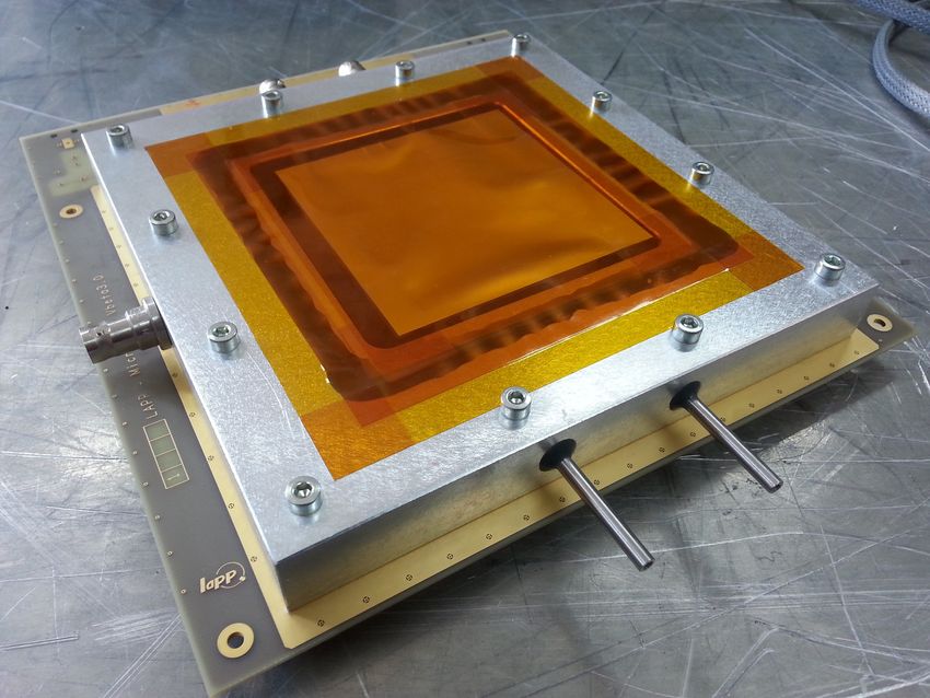
Resistive Micromegas for Particle Flow (sampling) calorimetry
→ at future linear colliders (ILC, CLIC)
HCAL with 1x1 cm2 pads, 4-5 lambda, 40 layers, W or Fe absorbers
Constrains on power-consumption (power pulsing), low noise (self-triggering)
High channel density (ASIC on PCB), active layer thickness (< 1 cm)
Advantage of resistive layer: removes spark protection diodes on PCB (→ cf. existing prototypes next slide)
(simpler design, more reliable, probably more cost effective)
→ at high-luminosity LHC (CMS)
Tail catcher of calorimetric system in forward region (completes Si-W ECAL+HCAL), upgrade for 2022 running
Constrains on rate capability, ageing, radiation hardness
Advantage of resistive layer: suppress or attenuate sparks, no or negligible dead time
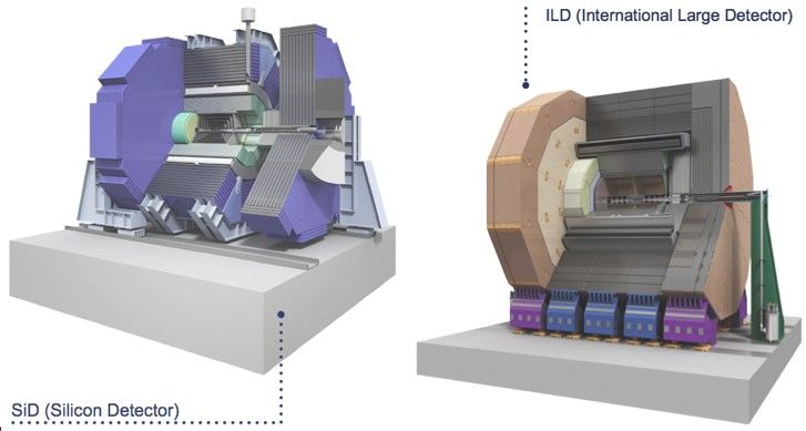
HCAL in SiD
Forward 2
calorimetry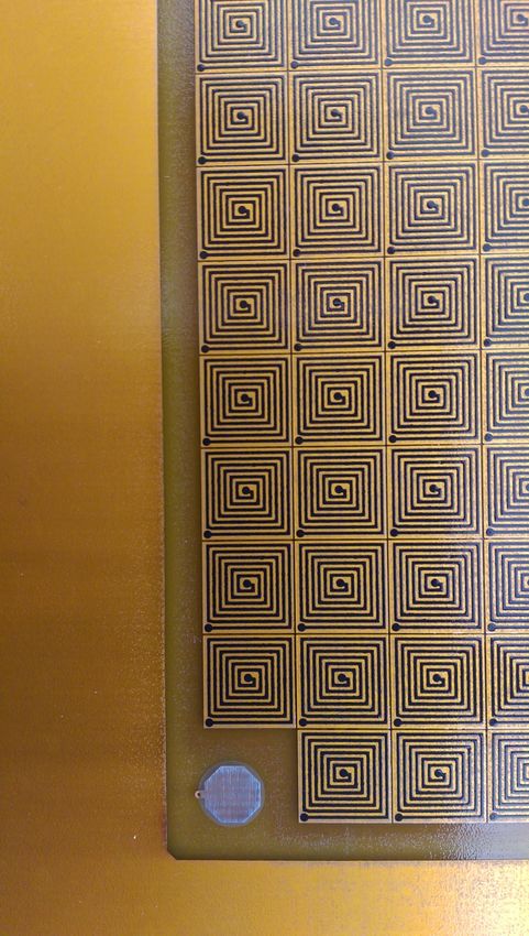
Prototypes for a LC

Large-area Micromegas with integrated front-end electronics
    1x1 m2 prototype based on 6 boards
    Each boards houses a Bulk Micromegas, 32x46 pads of 1x1 cm2 and 24 MICROROC ASIC (1536 channels)
    Non-resistive, ASIC are protected from sparking by diode networks on PCB

    4 prototypes were build and extensively tested in beam (RD51 and CALICE)
    2 publications reporting on construction (NIM A729 (2013) 90) & operating characteristics (A763 (2014) 221)

                                                                         Setup in H4 RD51 beam line (2012)
                                                           At next testbeam, the setup will be similar, but smaller

    PCB with ASIC & diodes                      6 Bulks in 1 chamber
            (recto)                                    (verso)                                                 3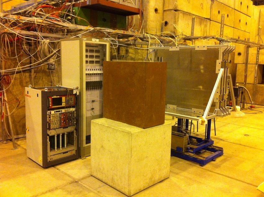
Highlights of testbeam results (LC-prototypes)
                                                       Low noise (1 Hz/ASIC in SDHCAL)

 Excellent
 uniformity

                                                 Spark rate / 150 GeV pion shower < 10-5

                            Efficiency > 95%

                                                                       Multiplicity ~ 1.15
   Rate capable at shower
    max (150 GeV pions)

                                                    Chb. 1              Chb. 2
                                                                                    4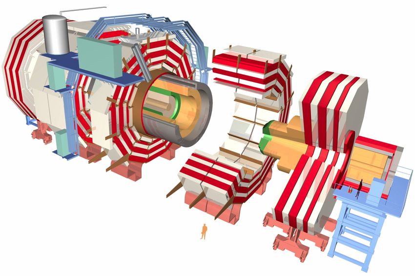
Requirements and R&D

What kind of resistive coatings?

Scalable to large area
→ charge evacuation to ground through the pad and not on the side → buried resistor
In this scheme, resistive and readout pads are connected by a resistor and separated by an insulator.

Fast evacuation of charge
→ small RC constant
R is the sheet resistance of the resistive pad
 + the buried resistance
C is controlled by the insulator thickness
and the pattern & size of the pad

What will we investigate?
Signal linearity will eventually determine the response of a sampling calorimeter
→ effect of rate but also of energy deposit (dE/dx) on gas gain

How is sparking affected
→ Careful monitoring of the mesh voltage & current
                                                                                                   5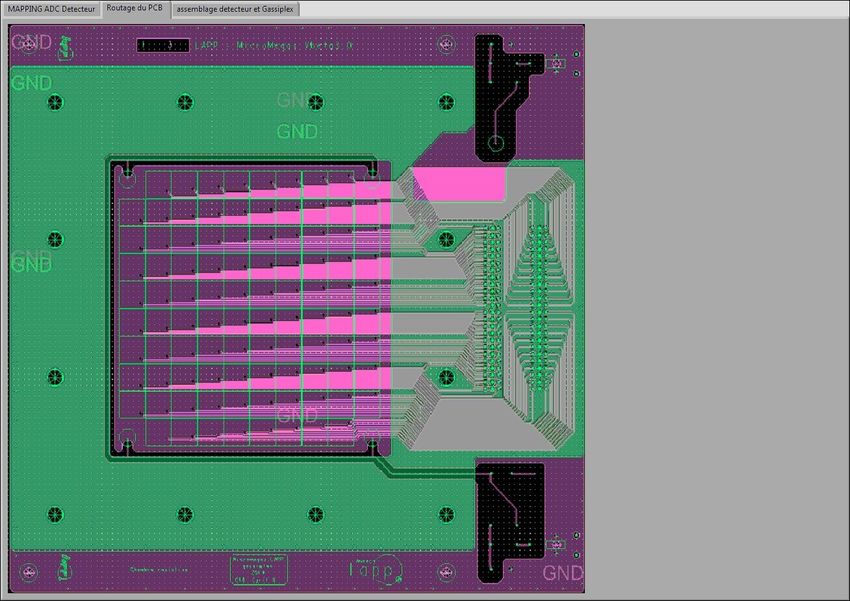
Resistive prototypes (1/2)

Study different configurations of buried resistors with small prototypes
Then, build a large-area prototype with the best configuration

Use simple PCB + re-use existing hardware (JINST 4 (2009) P11023)
Design of 10x10 cm2 with 1x1 cm2 pads
External electronics (Gassiplex), VME module -based DAQ, Labview sotfware

We first produced a prototype with different R-patterns
then prototypes with the same pattern over the pad matrix
                                                                       Rpad + Bulk
       Buried resistor                     Resistive pad

                                                                                     6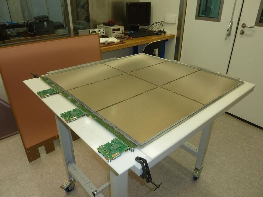
Resistive prototypes (2/2)

Study different configurations of buried resistors with small prototypes
Then, build a large-area prototype with the best configuration

Use simple PCB + re-use existing hardware (JINST 4 (2009) P11023)
Design of 10x10 cm2 with 1x1 cm2 pads
External electronics (Gassiplex), VME module -based DAQ, Labview sotfware

We first produced a prototype with different R-patterns
then prototypes with the same pattern over the pad matrix

     10x10 pad PCB                          Snake-like buried R

                                                                            7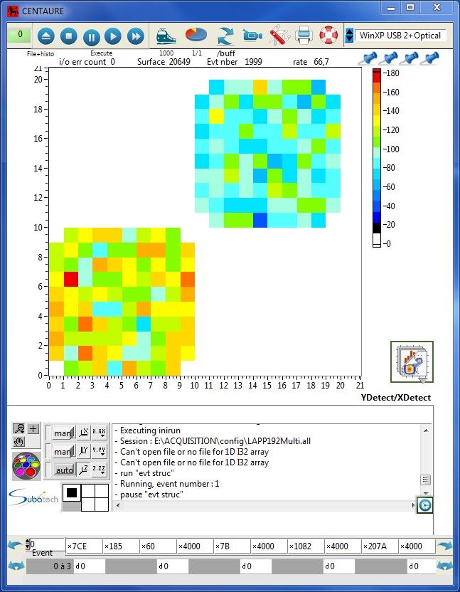
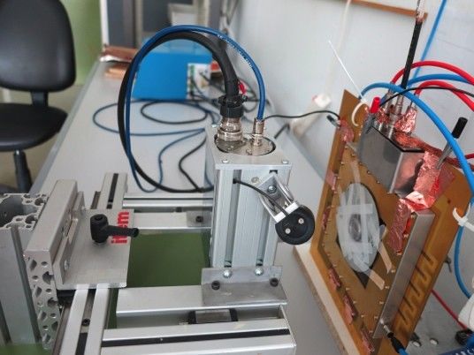
On-going measurements

Prior to the testbeam, we are checking the performance of all prototypes
At this moment, 5 prototypes were build, including a non-resistive as reference.

Rate scan
X-gun at Demokritos (3 keV,
RD51 Testbeam

Main goal: test prototypes in high-energy, high-rate, hadron showers

Setup (downstream of other setups)
2 scintillators + PMT + trigger electronics
1-10 steel absorber layers (30x50 cm2, 2 cm thick), can be removed in < 15 minutes
Detector stack: 2 non-resistive prototypes and 3-4 resistive prototypes (use non-R as telescope)
1 rack with VME modules for ASIC control & signal digitisation
2 PC (remote desktop from control room)
Gas: Ar/CO2 93/7 (2 bottles)

Beam 1: Muons
Detector calibration, single particle response

Beam 2: Pions (with & without absorbers)
Rate scan: 100 Hz to 100's of kHz
Energy scan: 10 to 100's of GeV
→ we will change the beam quite a bit!

What we would need from RD51: slow-control system for CAEN HV-unit (SY2527, 10 channels)
Crucial to study sparks                                                                  9
You can also read


