Instrumented baffles for Virgo - Lluïsa-Maria Mir for the Virgo Collaboration - IGFAE
←
→
Page content transcription
If your browser does not render page correctly, please read the page content below
Instrumented baffles for Virgo
                Lluïsa-Maria Mir
          for the Virgo Collaboration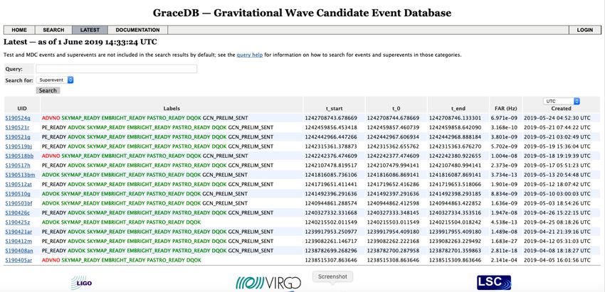
Performance of actual Virgo        2
  Sensitivity              Status

BNS range                BBH range
O3 data taking   3

@https://gracedb.ligo.org/latest/
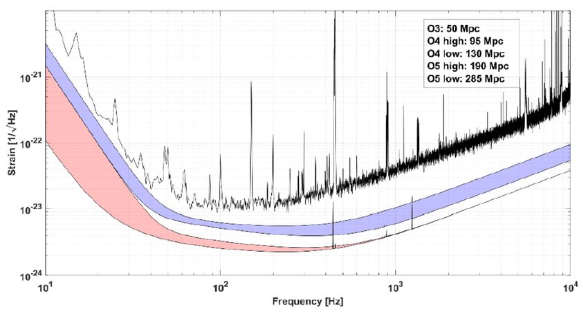
GW detector sensitivities                                         4

                                                     Ranges quoted for
                                                     1.4 M⊙+1.4 M⊙ BNS
                                                     and 30 M⊙+30 M⊙
                                                     BBH systems

               @ Living Rev Relativ (2018) 21:3
               https://doi.org/10.1007/s41114-018-0012-9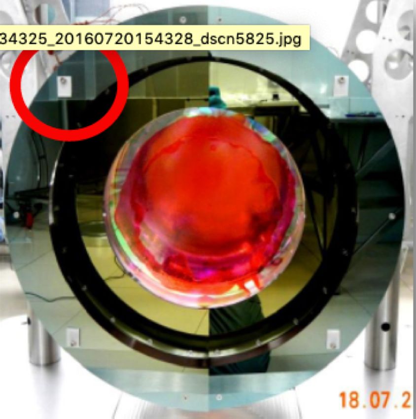
AdV+: Advanced Virgo upgrade                                   5
•   Next large upgrade in Virgo, synchronized with LIGO
•   Keep Virgo relevance in global network
•   Main change is the implementation of large end mirrors
•   All subsystems will improve their performance
•   Divided in two phases
         • Phase I (up to 2022): preparation during O3, installation before O4
            • 40 W laser input power
            • Signal recycling cavity
            • Newtonian noise cancellation
            • Frequency depending squeezing
         • Phase II (beyond 2022): preparation during O3-O4, installation before O5
            • 200 W laser input power
            • Larger mirrors
            • Larger beam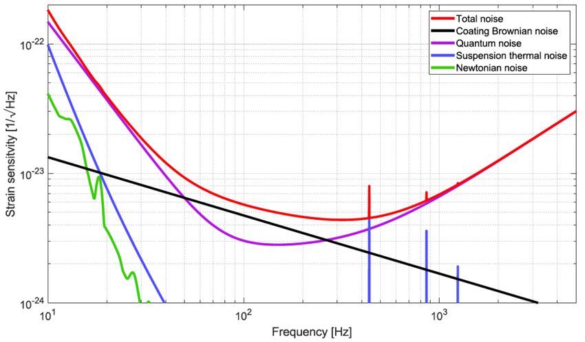
AdV+ expected sensitivity 6

AdV+ main sources of noise                   7

                             • Only fundamental
                               noises
                             • 40 W input power
                               assumed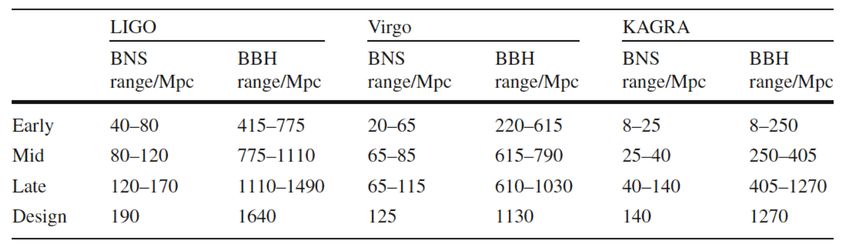
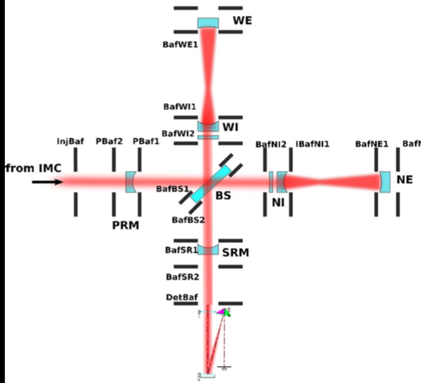
Importance of stray light control                               8
• Large fraction (70%) of light in interferometer lost in the form of stray light
• ITF full of passive (AR coated) baffles to eliminate diffused light across (99.5%)
• No real control/monitoring on where light goes
Importance of stray light control                                      9

• Stray light origin is hard to identify and its
  harmful effects difficult to mitigate
• Can occur at various places:
   • Laser beam diffraction
   • Scattering on surfaces and in substrate
      of optics
   • Small reflection on anti-reflective surface
      of optics
• Stray light might hit something with vibration
  and re-enter the main laser beam                 Simulation: most of the scattered
• Stray light might cause phase noises in the      light concentrated at low angles
  beam, indistinguishable from GW signal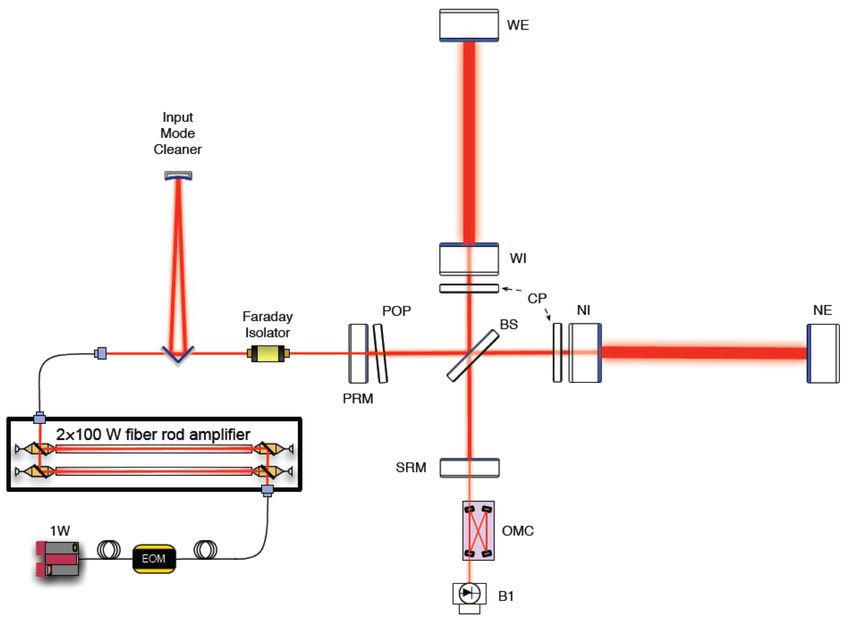
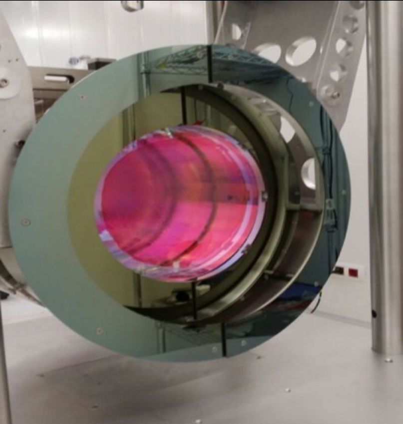
Instrumented baffles?                               10

• Beam not easy to localize during pre-alignment
• Rough targets installed on baffles to visualize beam
• Scattered light is monitored with cameras
• Sensors embedded in baffles will allow fully monitoring
  of small-angle scattered light:
   • Catch possible high order modes falling out the mirror
   • Discover possible ageing, contamination or worsening of mirror surfaces
• Need to study carefully:
   • Potential mirror contamination
   • Electromagnetic interferences with payload actuators
   • Tethering effects of possible new cables
   • Heat exchange with mirror or auxiliary mechanics
   • Mechanical interfaces and payload weight and balance
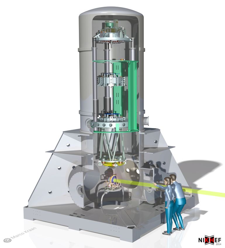
Input mode cleaner (IMC)                                                        11

@ Advanced Virgo Technical Design Report, VIR-0128A-12
                                                         https://www.nikhef.nl/pub/departments/mt/projects/virgo/inputmode/
Input mode cleaner (IMC) 12
• Current IMC operated successfully
• Mirror contaminated during
installation phase
• IMC round trip losses 200 ppm (larger
than required 100 ppm)
• Throughput smaller than expected
• Increased sensitivity to back-
reflected light
• Potential issue of radiation pressure
with increased power
• Want to improve control on payload
https://www.nikhef.nl/pub/departments/mt/projects/virgo/inputmode/IMC instrumented baffle 13 https://www.nikhef.nl/pub/departments/mt/projects/virgo/inputmode/ • Profit from replacement of IMC payload to install an instrumented baffle • Instrumented baffle can be tested immediately after O3 • Would serve as prototype and performance demonstrator for baffles of main mirrors in time for the phase II upgrade
IMC instrumented baffle requirements     14

• Maintain current performance of baffles in
  terms of reflectivity and scattering
• Have no significant effect on super-attenuator,
  payload and mirror
• Stringent constraints on
   • Mechanical design
   • Ultra-high vacuum compatibility of sensors
      and readout electronics
   • Readout strategy
   • Heat dissipation
   • Induced electromagnetic noise
IMC instrumented baffle design 15 • Two rows of photodiodes around inner diameter for good angular resolution • Four radial equiangular columns to know beam dispersion in radial direction • Each half-baffle 64 photosensors • PCB and electrical components are embedded in the baffle to minimize light scattering impact • Baffle thinned in some areas to allow space for these components • If additional scattering due to the presence of the gaps is unacceptable, we will consider filling them with an UHV compatible material
IMC instrumented baffle design                                16

     Current baffle design             Instrumented baffle design
Component          Weight (g) Component                    Weight (g)
Stainless steel      1887.47  Stainless steel                      1645.95
                              Photodiodes                            44.74
                              PCB                                    26.98
                              Electrical components       140 (estimated)
                              Glue                         20 (estimated)
                              Cables                      100 (estimated)
Total              1887.47    Total                                1977.66
                     Estimated difference = 90.19 g
New center of mass has moved away 1.34 mm with respect to the non-
instrumented current baffle
IMC instrumented baffle thermal simulation 17 • Baffle thermal gradient including main support structure when electronics are powered by 2.5 W and the temperature of the walls is 300 K • Between 2K and 4K are expected compared with the temperature achieved in the current baffle heated by the laser at a power of 25 W
Photosensors                                  18
• According to simulation
   • 5x10⁻⁶ to 5x10⁻⁵ W/cm2 per watt of laser input power reach baffle
   • A granularity of 1 cm2 allows detection of patterns produced by non-
     perfect alignments of the system
• Need sensors of about 1 cm2, which will receive 0.1 mW to 3.5 mW of light
• Temporal precision needed ~1 Hz
• Should have properties similar to baffle
   • Reflectivity below 0.5% to minimize the light non hitting the main mirror to
     be reflected back
   • Scattering off photosensors must be < 500 ppm
   • No significant amount of outgassing
• Specific R&D with Hamamatsu
• Proposed solution: 7.69 x 7.69 mm2, sensitive area of 6.97 x 6.97 mm2, based on
  S13955-01 photodiode, with ceramic support and underfilling removed
Photosensors robustness simulation 19
• Temperature in diode area after being directly
illuminated by a 30 W laser beam during 30 ms
and 1 W afterwards
• Temperature in region corresponding to nearby
sensor
• Even in this extreme scenario temperature of
baffle never goes beyond 50 CElectronics 20
• Digital readout output
• Sensor front end consists of an amplifier and an ADC input for each sensor
• All sensors in each half-baffle assembled in a single PCB
• Electronics biasing: single common cable, already installed
• Data transmission either wireless or optical fiber
• Demonstrator with multiple ways to transmit digital data wirelessly (Wi-Fi,
Bluetooth and Lora) being tested @VirgoFirst prototype 21 • Validate the Hamamatsu S13955-01 photodiode readout system • Get a platform for the photodiode characterization
First prototype                       22

Linearity test                     Polarization test
Dedicated tests           23

• First reflectivity test @ICMAB on sensors indicates
  coating is needed
• Scattering tests of full baffle to be done @ICMAB
  and @EGO
• UHV checks: residual gas analysis @ALBA
  synchrotron facility
• Aging tests and calibration
• Photodiode and electronics characterization:
   • Linearity and gain of the output signal in the
      range of expected light
   • Photodetection efficiency as a function of
      wavelength and temperature
DAQ and software control 24 • DAQ server to provide access to data generated by instrumentation • Functionality: • Hardware interface to enable communication • Continuous acquisition of data • Database to record data and other parameters (like errors) • Engineering UI for expert to access whole system functionality • Instrument interface to make information available to Virgo DAQ
Baffles close to main mirrors                   25

                       New (heavier) mirrors will
                       be installed (need for a
                       complete new payload)

                       Might end up instrumenting
                       also baffles in cryostat (to
                       ground)
Summary 26
• Stray light origin is hard to identify and its harmful effects difficult to mitigate
• Currently @Virgo scattered light is partly monitored with cameras
• IFAE plans to instrument baffles with photosensors to allow fully monitoring of
small-angle scattered light
@ M. Kraan and Th. S. Bauer, “IMC installation mirror procedure”, VIR-0435A-13You can also read


