INSTALLATION GUIDE BBCD082 - TO SUIT NISSAN NAVARA D23 2020+ FACELIFT
←
→
Page content transcription
If your browser does not render page correctly, please read the page content below
INSTALLATION
GUIDE
BBCD082
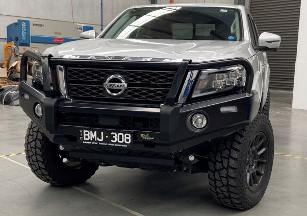
TO SUIT NISSAN NAVARA D23 2020+ FACELIFT
• Ironman 4x4 BBCD082 Bull Bar to suit Nissan Navara D23 2020+ Facelift.
• It will take approximately 4 hours to install.
BBCD082/110322
Ironman 4x4 does not recommend installation of antennas or aerials to the front of a bull
bar as it may cause the lane departure system to malfunction.
NOTE: This product has been tested for air bag compatibility
and therefore the mounting system MUST NOT be modified
IMPORTANT: Bull bar installations should only be done by a qualified person
and it’s the responsibility of this person to ensure correct fitment.
©Copyright 2022 Ironman 4x4 Pty Ltd. No part of this publication may be reproduced or replicated without the prior written consent of Ironman 4x4 Pty Ltd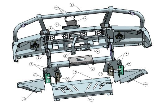
Installation Guide                                                                                                                                            BBCD082

                                                                    Before Installation

             PLEASE NOTE:
             It is always good practice to disconnect the battery while working on 12-Volt systems.
             Please check owner’s manual to see vehicle specific requirements as some models may
             need battery backup.
             Caution: Auto electrical work should only be carried out by a competent person. Vehicle
             wire colours are listed as a guide and may vary on some makes and models. The function
             of each wire should be checked before any connections are made.
             All wires tapped into the factory harness should be soldered and then insulated with
             electrical tape or heat shrink.
             Using only a LED test light, test all electrical components of the vehicle before and after
             wiring. This is to ensure that everything works correctly.
             IMPORTANT:
             Bull Bar installations should only be done by a qualified person, and it is the responsibility
             of this person to ensure correct fitment.
             Read instructions fully before commencing fitment.
             Do not remove labels from this bull bar. It is good practice to record the bull bar batch
             number on the customer’s job card for future reference.
             BULL BAR CARE INSTRUCTIONS:
             To maintain finish of the product, wash regularly using a PH neutral Car wash, hose
             off and chamois dry. Do not use acidic or alkaline cleaners. Plastic components can be
             maintained with a silicon spray or similar (non-acidic or alkaline based).
             The fitting instructions are correct at the time of publication date. Ironman 4x4 cannot be
             held responsible for any vehicle manufacturer changes. It is the installers responsibility to
             ensure correct fitment.
             It is important to work safely and use appropriate safety equipment while working.
             It is advised to purchase IBBPL082 patch loom because of the complex wiring system.
             Note: Pro-4X (with factory flares) requires factory flares to be trimmed to suit bull bar.
             Genuine fender flare caps can be purchased from Nissan to finish off cut section. It is
             advised to follow the guard to bumper body line to make cut line. Nissan Genuine part
             number- F3801-6KG0AAU, this part number was correct at the time of print. Check with
             your local Nissan Dealer.

                                                                                                                                                            Page 2 of 21
©Copyright 2022 Ironman 4x4 Pty Ltd. No part of this publication may be reproduced or replicated without the prior written consent of Ironman 4x4 Pty Ltd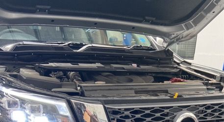
Installation Guide                                                                                                                                                                            BBCD082

                                                                      Bull Bar Parts List
                     1. Bull Bar                                                                              2. Winch Cradle

                                                                                                  QTY-1                                                                                     QTY-1

                     3. Grill Support Bracket            4. Chassis Bracket                 5. Wire Nut                        6. Radar Cover Plate                 7. License Plate Bracket
                                                         Spacer 5mm

                                               QTY-1                             QTY-4                              QTY-4                                   QTY-1                           QTY-1

                     8. Radar Mount                      9. Mesh                            10. Side Protection Plate          11. Side Protection Plate            12. Centre Protection
                                                                                            RHS                                LHS                                  Plate

                                               QTY-2                             QTY-1                              QTY-1                                   QTY-1                           QTY-1

                     13. Connection Bracket              14. Inner Chassis Bracket          15. Inner Chassis Bracket          16. Outer Chassis Bracket            17. Outer Chassis Bracket
                                                         RHS                                LHS                                RHS                                  LHS

                                               QTY-2                             QTY-1                              QTY-1                                   QTY-1                           QTY-1

                     18. Radar cover plate               19. Bolt, Nut, spring/flat         20. Bolt, spring/flat              21. Bolt, spring/flat                22. Bolt, Nut, spring/flat
                     buckle                              washers                            washers                            washers                              washers
                                                         M12×1.25×40mm                      M12×1.25×40mm                      M10×1.25×30mm                        M10×1.5×100mm

                                               QTY-4                            QTY-14                              QTY-4                                   QTY-4                       QTY-19

                     23. Bolt, spring/flat               24. Bolt, Nut, spring/flat         25. Bolt, Nut, flat washers        26. Bolt, Nut, flat washers          27. Bolt, spring/flat
                     washers                             washers                            M6×1×20mm                          M6×1×20mm                            washers
                     M8×1.25×25mm                        M8×1.25×25mm                                                                                               M6×1×20mm

                                              QTY-19                            QTY-11                             QTY-11                                   QTY-2                           QTY-2

                                                                              Tools Required
                                 Metric spanner set       Metric socket set        Air hacksaw              Tape measure             Drill and drill bits       Screwdriver set

                                                                                                                                                                                       Page 3 of 21
©Copyright 2022 Ironman 4x4 Pty Ltd. No part of this publication may be reproduced or replicated without the prior written consent of Ironman 4x4 Pty Ltd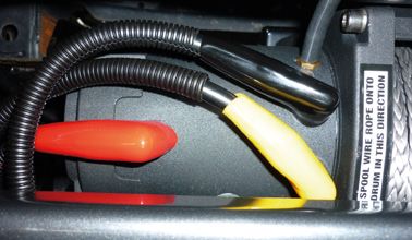
Installation Guide                                                                                                                                                                BBCD082

                                                                    Bull Bar Parts List
                                                                                                   1
                                                                                 18

                                                                                                                  6
                                                                                  7
                                                                           9

                                                                                                                                8
                                                                                                                                                            4
                                                                                            3
                                                               5
                                                      4                                                                                                         16
                                                                                                                           2
                                                                                                       13
                                                          17                                                                      14
                                                                                             15
                                                                                                                                                                           10

                                             11                                                                         12

                    17
                                                                                    22

                                                   15

                                                                                                                                                                     20          19

                                                                                                       4

                             4

                                                                     Bolt Tension Chart
                                                                                                           NOMINAL DIAMETER - COARSE THREAD
                                 Property Class             TORQUE ma
                                                                                          M6 x 1                  M8 x 1.25                M10 x 1.25            M12 x 1.25

                                                                   Nm                       10.5                        25                        49                  88
                                         8.8
                                                                   ft/lb                     7.7                        18                        36                  64

                                                                                                                                                                                Page 4 of 21
©Copyright 2022 Ironman 4x4 Pty Ltd. No part of this publication may be reproduced or replicated without the prior written consent of Ironman 4x4 Pty Ltd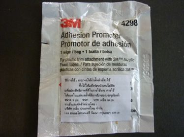
Installation Guide                                                                                                                                            BBCD082
      1.	Before installation, check bull bar
          application is compatible with your
          vehicle.

                 Remove and retain number plate, if
                 fitted, to be reinstalled later.

                 Disconnect negative battery
                 terminal.

      2.         Unwrap bull bar. Check overriders
                 and light assemblies are tight in
                 the bull bar before installation.

      3.          Remove and retain top plenum
                  cover. Ensure to keep all plastic
                  clips. Once cover is removed,
                  disconnect front camera wiring.

      4.         Once plenum cover is removed,
                 disconnect front camera wiring
                 and front radar wiring. Unclip the
                 grille and store in a safe place.

                 NOTE: It is important not to drop
                 both the camera and sonar as it
                 will cause damage.

      5.         Remove all factory bumper bar
                 retaining clips and bolts (including
                 splash tray clips). If vehicle is fitted
                 with factory fog lights, disconnect
                 wiring. Unbolt and remove factory
                 stone tray/bash plate. Now unclip
                 and remove factory bumper.

                                                                                                                                                            Page 5 of 21
©Copyright 2022 Ironman 4x4 Pty Ltd. No part of this publication may be reproduced or replicated without the prior written consent of Ironman 4x4 Pty Ltd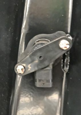
Installation Guide                                                                                                                                            BBCD082
      6.         Remove and disregard factory lower
                 headlight bumper retaining clips and
                 side guard bumper and clips (white).
                 Remove lower centre air dam, side
                 dams can be left in place and may
                 need to be trimmed. The factory bar
                 reinforcement can now be removed.

      7.         Carefully remove centre radar,
                 making sure not to drop sensor.
                 Remove radar from the factory
                 bracket to be reinstalled.

      8.         Remove and disregard both left
                 and right grille support brackets.

      9.         Locate the 2 outer chassis holes
                 on both sides of the outer chassis
                 rail. Test fit chassis reinforcement
                 brackets. Once happy with the hole
                 location remove brackets.

                                                                                                                                                            Page 6 of 21
©Copyright 2022 Ironman 4x4 Pty Ltd. No part of this publication may be reproduced or replicated without the prior written consent of Ironman 4x4 Pty Ltd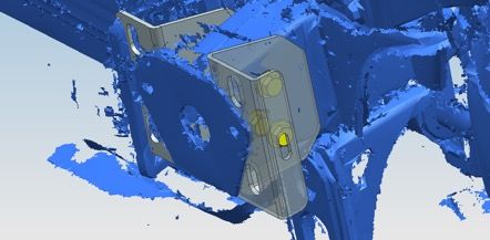
Installation Guide                                                                                                                                            BBCD082
      10. Using a 10mm drill bit, drill through
          both sides of the chassis.

                 NOTE: Its good practice to wear safety
                 googles, and keep drill square to the
                 rail to be able to drill straight.

      11. It is good practice to use a
          telescope magnet and remove
          all metal swarf from inside the
          chassis rail. Once holes are
          cleaned, paint the bare metal
          surface.

      12. Bolt both sides of the chassis
          reinforcement brackets to the
          chassis using the hardware
          provided. Make note to place the
          wing bolting slot to the outside of
          the rail.

      13. Fit winch cradle to front of vehicle.
          Do not tighten the bolts at this
          stage as adjustment will be
          required once bull bar is installed.
          Take note of gap between chassis
          face and cradle, it may need shims
          fit. Install shims supplied on either
          side of the cradle to bracket. If
          outer air dams are still installed,
          you may need to trim to allow
          clearance for cradle.

                                                                                                                                                            Page 7 of 21
©Copyright 2022 Ironman 4x4 Pty Ltd. No part of this publication may be reproduced or replicated without the prior written consent of Ironman 4x4 Pty Ltd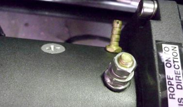
Installation Guide                                                                                                                                            BBCD082
      14. Find a fixed point on the vehicle, take
          measurements, square up the cradle.
          Repeat on both sides until cradle is
          centred.

      15. If winch is being installed, refer to
          winch installation instructions on
          page.

                 Wiring for fog lights, blinkers,
                 parker and DRL can now be wired.
                 Ironman4x4 recommends using a
                 bull bar patch loom for plug and
                 play ease.

                 If fitting Ironman 4x4 recovery
                 points, do this now.

      16. Install grille support bracket as shown.

      17. Using the grille honeycomb openings
          as a guide mark a line across from
          the outer edge to the centre radar
          rectangular cover section.

                                                                                                                                                            Page 8 of 21
©Copyright 2022 Ironman 4x4 Pty Ltd. No part of this publication may be reproduced or replicated without the prior written consent of Ironman 4x4 Pty Ltd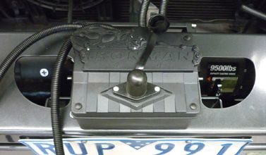
Installation Guide                                                                                                                                            BBCD082
      18. Trim grille.

                 NOTE: Its good practice to wear safety
                 goggles.

      19. Install grille loosely and mark the 2
          holes for the grille support from in
          behind the grille.

      20. Drill 2 x 6.5mm holes.

      21. Install the radar panel bracket to the
          lower inside of the centre grille insert
          using M6 hardware. Make note of the
          top of the grille insert and top of the
          radar.

                                                                                                                                                            Page 9 of 21
©Copyright 2022 Ironman 4x4 Pty Ltd. No part of this publication may be reproduced or replicated without the prior written consent of Ironman 4x4 Pty Ltd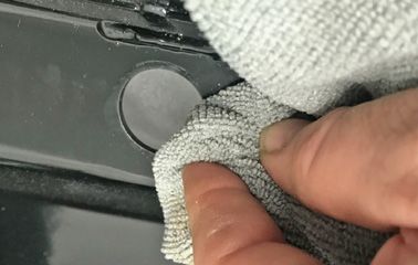
Installation Guide                                                                                                                                             BBCD082
      22. Install the second radar panel bracket
          to the upper inside of the centre grille
          insert.

      23. Install radar grille insert into the bull
          bar making sure the grille and radar
          are square. Once happy install plastic
          protective cover with clips provided.

      24. Reinstall trimmed grille using original
          fasters and M6 bolts to new grille
          support bracket.

      25. Install bull bar to cradle using M12
          hardware supplied. Do not tighten.

      26. Centralise the bull bar to the vehicle’s
          bodywork. Tighten the bolts holding
          the chassis brackets and cradle to the
          chassis.

                                                                                                                                                            Page 10 of 21
©Copyright 2022 Ironman 4x4 Pty Ltd. No part of this publication may be reproduced or replicated without the prior written consent of Ironman 4x4 Pty Ltd
Installation Guide BBCD082
27. Align bull bar with vehicle ensuring
there is a 15-20mm gap between
wing of bull bar, mudguard, and
headlight. Tighten all cradle bolts to
bull bar.
28. Drill and pin bar into position using
M10 bolts, washers and nuts supplied.
29. Connect blinkers, parkers, and fog
lights (if applicable).
Refer to wiring diagram on page 21.
30. Install the protection plate brackets to
bull bar cradle using the inner bolts as
shown. Repeat on the other side.
NOTE: Only use inner bolts at this
stage as shown.
Page 11 of 21
©Copyright 2022 Ironman 4x4 Pty Ltd. No part of this publication may be reproduced or replicated without the prior written consent of Ironman 4x4 Pty LtdInstallation Guide BBCD082
31. Install centre protection plate with
black M8 bolts provided.
32. Install both wing protection plates with
black M8 bolts provided.
33. Install number flip bracket and number
plate to the vehicle with M6 hardware
supplied.
Page 12 of 21
©Copyright 2022 Ironman 4x4 Pty Ltd. No part of this publication may be reproduced or replicated without the prior written consent of Ironman 4x4 Pty LtdInstallation Guide BBCD082
34. Trim guard liners, drill 2 holes as
shown and secure in place behind
wing protection plates with cable ties
(not supplied).
NOTE: we recommend removing the
upper sound deadening as this may be
visible and will make it easier to trim.
35. Depending on the model of the vehicle
you may need to notch out the guard
liner from guard join to allow liner to
tuck into bull bar wing end.
36. Reconnect front camera wiring and
radar wiring.
Reinstall top plenum grille and connect
negative battery terminal.
Page 13 of 21
©Copyright 2022 Ironman 4x4 Pty Ltd. No part of this publication may be reproduced or replicated without the prior written consent of Ironman 4x4 Pty LtdInstallation Guide BBCD082
Once Bull Bar is Installed
Ensure all bolts are tensioned correctly, it is good practice to do a vehicle pre trip check before
heading away or every 10k kms. Visually inspect bull bar and hardware, retention bull bar
hardware or when needed.
Check the operation of the blinkers, park lights, fog-lights and winch if installed and ensure that
they are all functioning correctly. Make sure all electrical wiring is clear of sharp edges and is
secured correctly.
If vehicle is fitted with parking sensors, radars and or front cameras check they are operating
correctly. Some makes and models may need to return to the dealership for recalibration.
Stand back and admire your work.
Page 14 of 21
©Copyright 2022 Ironman 4x4 Pty Ltd. No part of this publication may be reproduced or replicated without the prior written consent of Ironman 4x4 Pty LtdInstallation Guide BBCD082
Plastic Parking Sensor Installation
IMPORTANT: For parking sensors to function correctly these instructions must
be followed closely.
Before removing sensors from original bumper bar, note the location and
orientation of each sensor so when they are fitted the bullbar this can be
duplicated.
1. Remove rubber grommets from
sensor holes in bullbar.
2. Remove blank from sensor holder
and trim any excess plastic from
inside opening if applicable.
Page 15 of 21
©Copyright 2022 Ironman 4x4 Pty Ltd. No part of this publication may be reproduced or replicated without the prior written consent of Ironman 4x4 Pty LtdInstallation Guide BBCD082
3. Fit sensor with factory silicone
sleeve to the sensor holder and
secure using clamping plate and
screws provided. Do not over
tighten. Clamping plate has a flat
side for thicker sensors and a
raised section on the other side for
thinner sensors. It is important that
clamping plate is the correct way
around as sensor will false alarm
if excess pressure is applied to the
sensor body.
4. Clean inside of bullbar around
sensor holes and mounting surface
of sensor holders using wax and
grease remover.
Page 16 of 21
©Copyright 2022 Ironman 4x4 Pty Ltd. No part of this publication may be reproduced or replicated without the prior written consent of Ironman 4x4 Pty LtdInstallation Guide BBCD082
5. Apply adhesion promoter to
mounting surfaces around sensor
holes and on sensor holders. This
step is important to ensure sensor
holders adhere properly to the
bullbar.
6. Remove protective film from one
side of double-sided tape and
apply to mounting surface of
sensor holder.
Page 17 of 21
©Copyright 2022 Ironman 4x4 Pty Ltd. No part of this publication may be reproduced or replicated without the prior written consent of Ironman 4x4 Pty LtdInstallation Guide BBCD082
7. Remove protective film from
double-sided tape and apply
sensor holder/sensor to bullbar
making sure sensors are in the
same positions as they were in the
original bumper and in the same
orientation.
Page 18 of 21
©Copyright 2022 Ironman 4x4 Pty Ltd. No part of this publication may be reproduced or replicated without the prior written consent of Ironman 4x4 Pty LtdInstallation Guide BBCD082
Winch Installation
1. Bolt winch to cradle. Bolt fairlead
to recess in front of bull bar using
bolts, washers and nuts provided.
2. Fit bull bar to vehicle referring to
steps of bull bar fitting instructions.
3. Mount control box in desired
location.
4. Connect three colour coded cables
to the corresponding poles on
winch motor.
Page 19 of 21
©Copyright 2022 Ironman 4x4 Pty Ltd. No part of this publication may be reproduced or replicated without the prior written consent of Ironman 4x4 Pty LtdInstallation Guide BBCD082
5. Connect the thin black earth wire
and negative battery cable to the
earth connection on the opposite
side of winch motor.
6. Run the positive and negative
battery cables into the engine bay
taking care to secure cables away
from any sharp or moving objects.
7. Connect positive and negative
battery cables main battery of
vehicle (Not Auxilliary Battery).
8. Attach breather hose to barb fitting
on winch motor. Run hose to the
highest available point in engine
bay and cable tie in position. Cable
tie hose away from any sharp, hot
or moving objects.
Refer back to step 18 of the Bull
Bar fitting instructions on page 7
Page 20 of 21
©Copyright 2022 Ironman 4x4 Pty Ltd. No part of this publication may be reproduced or replicated without the prior written consent of Ironman 4x4 Pty LtdInstallation Guide BBCD082
Wiring Diagrams
PARK LIGHT & INDICATOR
Red
Daytime Running Light
Brown
Park Light
Yellow
Indicator Light
White
Ground
If vehicle is not fitted with DRL, leave red wire disconnected
FOG LIGHTS
Ground Red
Red Lamp
Fuse
85 30
Connector
87
86 87a Relay
Black
Blue
Battery Lamp
Parklight Switch
SPST
Ground
White
Ground
WITHOUT FACTORY FOG LIGHTS
Ground Red
Red Lamp
Fuse
85 30
Connector
87
86 87a Relay
Black
Blue
Battery Lamp
Positive power supply
at connector to factory fog light
Page 21 of 21
©Copyright 2022 Ironman 4x4 Pty Ltd. No part of this publication may be reproduced or replicated without the prior written consent of Ironman 4x4 Pty LtdYou can also read