Inertial Electrostatic Confinement; Small Scale Nuclear Fusion for Non Energy Applications
←
→
Page content transcription
If your browser does not render page correctly, please read the page content below
Inertial Electrostatic Confinement; Small Scale
 Nuclear Fusion for Non‐Energy Applications
                   Daniel R. Knapp
         Medical University of South Carolina
                         and
             Wilhelm Bratwurst Institute
        Charleston, South Carolina, 29425 USA

          ICTP‐IAEA College on Advanced Plasma Physics
                          August, 2014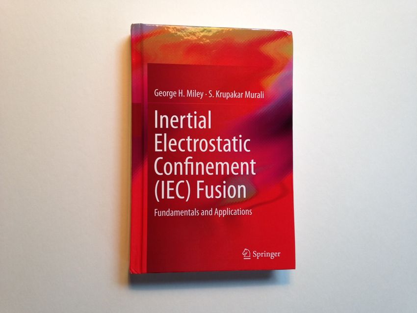
Major Current Projects in
      Nuclear Fusion

                                           Tokamak
                                       ITER, Cadarache, FR

Laser Inertial Confinement
National Ignition Facility, LLNL, US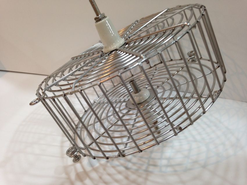
Some Other (Smaller) Approaches to Nuclear Fusion

  Z‐Pinch (Sandia Laboratories Z‐Machine)
                                            “Field Reversed Configuration” (Tri Alpha Energy)

Dense Plasma Focus             Magnetized Target Fusion       Stellarators
(Lawrenceville Plasma Physics) (General Fusion Inc.)    (e.g. Wendelstein 7‐X in Germany)
The topic of this presentation (still smaller devices):

Inertial Electrostatic Confinement (IEC) Fusion:

    Farnsworth‐Hirsch Fusor
    Polywell® (EMC2)
    Other gridless IEC designs
    Lockheed’s new device (IEC?)

   ( IEC is NOT “Cold Fusion” !!!)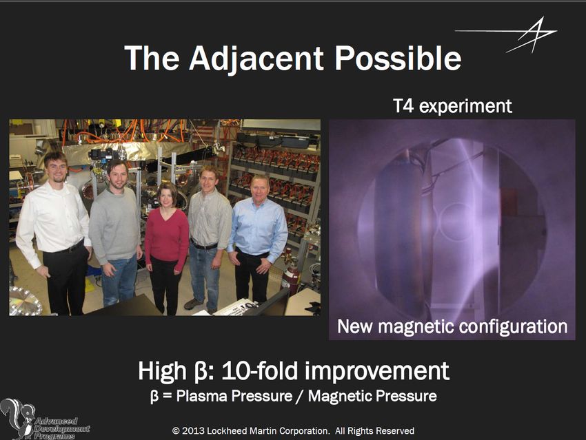
Nuclear Fusion Reactions

2H   + 3H → 4He (3.5 MeV) + n0 (14.1 MeV)

2H + 2H → 3H (1.01 MeV) + p+ (3.02 MeV) [50%]
2H + 2H → 3He (0.82 MeV) + n0 (2.45 MeV) [50%]

2H   + 3He → 4He (3.6 MeV) + p+ (14.7 MeV)

p+ + 6Li → 4He (1.7 MeV) + 3He (2.3 MeV) *

p+ +   11B   → 3 4He (8.7 MeV) “aneutronic”

* where it all started – Cockcroft & Walton, 1932
Nuclear Fusion Cross Sections
     Temperature in degrees Kelvin
     1.1 X 10⁸    1.1 X 10⁹     1.1 X 10¹⁰
          l            l            l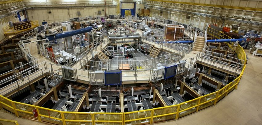
Beam‐Target Nuclear Fusion

ion source
               2H+   ion beam

     +

                                                    Ti target

                                Schlumberger Ltd.
Beam‐Target Nuclear Fusion – Gas Phase Target

       Philo Farnsworth
inventor of electronic television
     8/19/1906‐3/11/1971

                         The Farnsworth Invention
                         a play by Aaron Sorkin
                         Music Box Theatre
                         Broadway, New York
                         December 3, 2007 –
                         March 2, 2008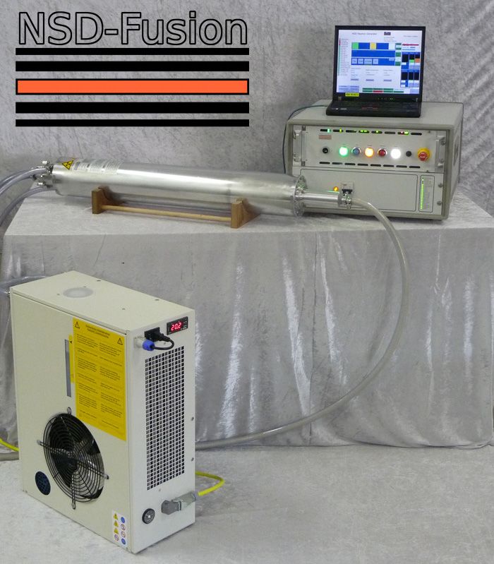
Farnsworth’s Other Invention ‐ IEC Fusion Device

        P. T. Farnsworth, U.S. Patent 3,258,402 June 28, 1966
Farnsworth wasn’t actually the first : As Professor Linder mentioned last week, Oleg Lavrentyev actually put forth the idea first (1950), but Andre Sakarov didn’t think it would work. After the secrecy surrounding fusion work was lifted, Lavrentyev ultimately published his idea: Lavrentyev, O.A. et al. (1963) Jenergiya i plotnost’ionov v jelektromagnitnoj lovushke. Ukrain. Fiz. 8:440–445.
Farnsworth Fusor

P. T. Farnsworth, U.S. Patent 3,386,883 A June 4, 1968
Farnsworth–Hirsch Fusor
                                                           high negative potential
                                                         (tens of kV.) on center “cathode”
“ion source” grid
(positive relative to
both cathode and anode)
                                                             ca. 1 Pa. deuterium gas

                                                                grounded shell “anode”

                                                                 Filament electron source

          G.A. Meeks, R.L. Hirsch, U.S. Patent 3,530,497 September 22, 1970
Basic “Farnsworth Fusor”
−H.V
vacuum & gas supplyArguments that IEC Fusion Cannot Yield Net Energy Bremsstrahlung losses exceed the fusion power produced. T. H. Rider, A general critique of inertial‐electrostatic confinement fusion systems, M.S. thesis, Massachusetts Institute of Technology, 1994. T.H. Rider, "A general critique of inertial‐electrostatic confinement fusion systems, Physics of Plasmas 2 (6), p. 1853‐1872 (Jun. 1995). Coulomb collisions →Maxwellian distribution on the ion–ion collisional time scale; power required to prevent this is greater than the fusion power produced. W.M. Nevins, Can inertial electrostatic confinement work beyond the ion‐ion collision time scale? Physics of Plasmas 2: 3804‐3819, 1995.
Applications of Nuclear Fusion

1. Energy production

2. Neutron and other energetic particle sources
      a. landmine detection
      b. nuclear materials detection
      c. neutron radiography
      d. neutron transmutation doping
      e. medical isotope production
      f. research applications

3. Spacecraft propulsion
IEC Neutron Source (107/sec) for Landmine Detection Institute of Advanced Energy, Kyoto University
Pulsed 200 kV IEC Device for Nuclear Materials Detection

Institute of Advanced Energy, Kyoto University
Commercial IEC Fusion Neutron Generator

                               NSD‐GRADEL‐FUSION, Luxembourg
Medical Isotope Production Using IEC Neutron Generator
Molybdenum‐99 precursor of Technetium‐99m
The most widely used isotope for medical imaging
2H + 2H → 3He (0.82 MeV) + n0 (2.45 MeV)
235U (low enrichment; water solution) + n0 → 99Mo (fission product)
Molybdenum‐99 (99Mo) → Techne um‐99m (99mTc)
Madison, Wisconsin, USAUniversity Research Groups Pursuing IEC Fusion Research
1. University of Wisconsin (US)
2. University of Illinois (US)
3. University of Maryland (US)
4. Tokyo Institute of Technology (Japan)
5. Kyoto University (Japan)
6. Tokai University (Japan)
7. Kansai University (Japan)
8. University of Sydney (Australia)
9. Shahid Beheshti University (Iran)
10. Gazi University (Turkey)
Primary scientific meeting: U.S.‐Japan Workshop on Inertial Electrostatic Confinement Fusion
11th – 2009 University of Wisconsin
12th – 2010 Kansai University, Osaka
13th – 2011 University of Sydney
14th – 2012 University of Maryland
15th – 2013 Kyoto University
16th – 2014 University of WisconsinProblems Presented by the Grid in a Gridded Fusor
1. Ion bombardment heats the grid leading to
thermionic electron emission.
2. Electron emission causes power loss and
neutralization of the fuel ions.
3. Grid heating eventually melts the grid.Grid Heating in Fusor
The Polywell®

                                   3D Magnetic Trap               Four Coil Polywell
    Robert W. Bussard                                             http://www.polywellnuclearfusion.com
     8/11/1928‐10/6/2007

                                                              Computer plot of magnetic
                                                               field lines from four coils
         Wiffle Ball                                          www.mare.ee

R. W. Bussard, 57th International Astronautical Congress (IAC) Valencia, Spain, October, 2006.
http://www.askmar.com/ConferenceNotes/2006‐9%20IAC%20Paper.pdf
Polywell Devices – EMC2 Inc.
WB‐1 permanent magnets
WB‐4
WB‐2
WB‐5
WB‐3
WB‐6
109 DD fusions/sec at a potential well of 10 kV.Polywell Research Support from the U.S. Navy
“R&D‐ ENERGY: NUCLEAR (APPLIED RESEARCH/EXPLORATORY DEVELOPMENT)”
www.fpds.gov/ezsearch/
May 21, 2013 $780,000 “Plasma Wiffleball 8.0”
April 29, 2013 $300,000 “Plasma Wiffleball 8.0”
Feb. 25, 2013 $600,000 “Incremental funding for Plasma Wiffleball 8.0”
Aug. 23, 2012 $1,120,000 “Plasma Wiffleball 8.0”
May 03, 2012 $1,200,000 “Plasma Wiffleball 8.0”
June 22, 2011 $2,022,678 “Plasma Wiffleball concept exploration”
June 08, 2011 $100,000 “R&D concept exploration on Plasma Wiffleball 8.0”
Jan. 20, 2011 $1,000,000 “Research & development of the AGEE Plasma Wiffleball”
Sept. 10, 2010 $1,350,000 “The contractor shall construct and test a small scale MG
insulated, Wiffleball Polyhedral device, WB8”
Sept.11, 2009 $3,216,825 “..concept exploration and technology demonstration of the
Advanced Gaseous Electrostatic Energy (AGEE) concept..WB8”
May 20, 2009 $331,174 “Wiffleball 7.1”
March 03, 2009 $299,843 “Wiffleball 7.1”
Dec. 17, 2008 $99,355 “Research study for the AGEE Development”
Dec. 08, 2008 $99,355 “Polywell Fusion Device Ion Injection Gun”
Nov. 5, 2008 $93,123 “Advanced Gaseous Electrostatic Energy ”
August 21, 2007 $1,750,000 “applied/exploratory engineering (fusion research)”
Total Polywell funding to date ‐ $17,558,191 (including 1997‐2005)Direct Energy Conversion
p+ + 11B → 3 4He (8.7 MeV)
electric
current
fusion
reactor
heliumThe first regular publication by the EMC2 group: J. Park, N.A. Krall, P.E. Sieck, D.T. Offermann, M. Skillicorn, A. Sanchez, K. Davis, E. Aldrson, G. Lapenta, High Energy Electron Confinement in a Magnetic Cusp Configuration, arXiv:1406.0133 (2014)
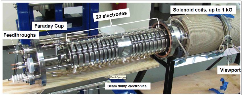
Multiple Ambipolar Beam Line Experiment (“MARBLE”)
10kV 0V   6.6kV 0V 5.1 kV 0V 3.1kV 0V 1.5kV   0V

Conical Focusing/ Accelerating Electrodes               Multiple Recirculating Beams

     A. Klein, The Multiple Ambipolar Beam Line Experiment (MARBLE), presented at the 13th
     U.S. ‐ Japan Workshop on Inertial Electrostatic Confinement Fusion, Sydney, 2011.
Linear Electrostatic Ion Trap L. H. Andersen, O. Heber, D. Zajfman, Physics with electrostatic rings and traps, Journal of Physics B 37, R57–R88, 2004. A. V. Ermakov and B. J. Hinch, An electrostatic autoresonant ion trap mass spectrometer, Review of Scientific Instruments 81, 013107, 2010.
Multiple Ambipolar Beam Line Experiment (“MARBLE”)
10kV 0V   6.6kV 0V 5.1 kV 0V 3.1kV 0V 1.5kV   0V

Conical Focusing/ Accelerating Electrodes               Multiple Recirculating Beams

     A. Klein, The Multiple Ambipolar Beam Line Experiment (MARBLE), presented at the 13th
     U.S. ‐ Japan Workshop on Inertial Electrostatic Confinement Fusion, Sydney, 2011.
Multiple Ambipolar Beam Line Experiment (“MARBLE”) A. Klein, The Multiple Ambipolar Beam Line Experiment (MARBLE), presented at the 13th U.S. ‐ Japan Workshop on Inertial Electrostatic Confinement Fusion, Sydney, 2011.
Turning Regions in Electrostatic Traps

                                                −H.V

              turning regions

Linear Electrostatic Trap

                                Hirsch ‐ Farnsworth Fusor
Fusor in “Star Mode”
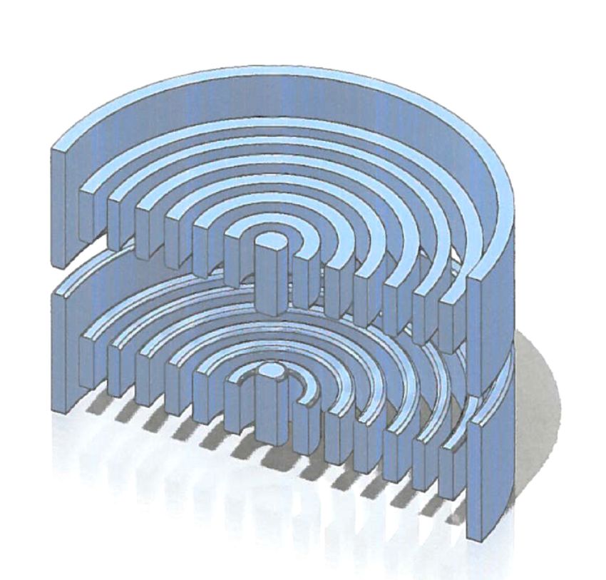
Photo from Wikipedia CommonsGridless Planar (Disc) Electrostatic Ion Trap turning region
Planar Electrostatic Ion Trap

   Rotate around vertical axis

D.R. Knapp, U.S. Patent Application Pending 2013.
Proposed Planar Electrostatic Ion Trap Mass Spectrometer
L. Ding, R. Badheka, Z. Ding, H. Nakanishi, A Simulation Study of the Planar Electrostatic Ion Trap
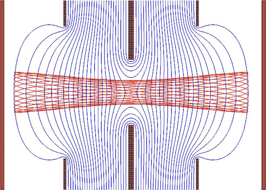
Mass Analyzer, J. Am. Soc. Mass. Spectrom. 24: 356‐364, 2013.Planar Electrostatic Ion Trap
Simulation of ion trajectories for
ions originating at single point with
0.1 eV tangential K.E
Rotate around vertical axis
Cutaway view with top electrode rings removedHow to Generate Ions with Tangential K.E. Inside the Trap?
Brooks Automation VQM 830 Residual Gas Analyzer
Prototype Single Potential Trap under Construction
What’s new in fusion development?
Recent Report of Work at the Lockheed Martin Skunkworks

          “Solve For X is a place to hear about and discuss radical
               technology ideas for solving global problems.”

            Posted January 11, 2013 www.solveforx.com
www.solveforx.com/moonshots/solve‐for‐x‐charles‐chase‐on‐energy‐for‐everyone
www.solveforx.com/moonshots/solve‐for‐x‐charles‐chase‐on‐energy‐for‐everyone
Summary

Several alternative approaches to nuclear fusion are under study.

Some offer the possibility of small power reactors.

Some are particularly useful for non‐energy applications.

IEC devices are particularly simple for such applications.

Gridless IEC devices could yield much improved performance.
End
Extra Slides
Cylindrical Geometry/Linear Electrostatic Trap IEC Device

   G. H. Miley, A portable neutron/tunable X‐ray source based on inertial
   electrostatic confinement, Nucl. Instrum. Meth. Physics Res. A 422, 16‐20, 1999.
Proposed Beam – Beam Collision Device

                 Ion Sources Biased at High Positive Potential

                           Magnetic Field Coils

              A Conceptual Drawing of the Neutron Generator

H. Momota and G. H. Miley, Neutron Source Based on a Counter‐Deuterium
Beam Linear IEC, J. of Fusion Energy 28, 191‐194, 2009.
The Wilhelm Bratwurst Institute for Applied Physics Research
Elmore‐Tuck‐Watson Device
                          −H.V                                            +H.V

     Hirsch ‐ Farnsworth Fusor                            Elmore ‐ Tuck ‐ Watson

W. C. Elmore, J. L. Tuck, K. M. Watson, On the Inertial‐Electrostatic Confinement of a Plasma,
Physics of Fluids 2(3)1959.
Farnsworth–Hirsch Fusor
high negative potential
(tens of kV.) on center “cathode”
“ion source” grid
(positive relative to
both cathode and anode)
ca. 1 Pa. deuterium gas
grounded shell “anode”
Filament electron source
G.A. Meeks, R.L. Hirsch, U.S. Patent 3,530,497 September 22, 1970 — “Hirsch–Meeks Fusor”IEC Fusor Science Fair Project Taylor Wilson explaining his fusor science fair project to Barak Obama. 2/7/2012
You can also read