ASCEND - Base Comfort - Glideaway
←
→
Page content transcription
If your browser does not render page correctly, please read the page content below
ASCEND
   OWNERS
    OWNERS MANUAL
            MANUAL
MANUAL DE INSTRUCCIONES

    Comfort Base
                          ®

       Lifestyle Series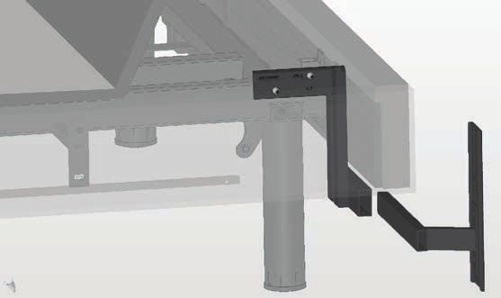
Contents

Safety Information ...........................................................................2
What Is Included ...............................................................................5
Assembly - Base ...............................................................................6
Assembly - Head Board Bracket...................................................9
Location of Controls - Remote ..................................................11
Operation - Main...........................................................................12
Operation - Sleep Enhancement ...............................................14
Operation - Setting the Memory Presets ..............................15
Available Accessories ....................................................................16
Operation - Linking the Remote................................................17
Troubleshooting .............................................................................18
Specifications..................................................................................20
Technical Assistance .....................................................................20
Service Requirements ..................................................................20
Cleaning ...........................................................................................20
Warranty ..........................................................................................21
Registration .....................................................................................22

Spanish starts on page 23.
Español comienza en la página 23.

User Info
Please take a moment and write down the serial number in the space provided below, in
case you need to refer to it in the future. This information can be found by raising the head
section of the bed.

SKU:                CBE2ASC
Serial Number ________________________________________________________
This number will be required for future service claims.

                                                             1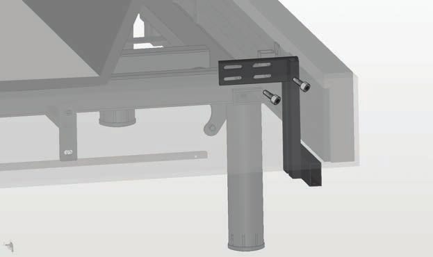
SAFETY INFORMATION
                         ATTENTION!
      IMPORTANT SAFETY INSTRUCTIONS. SAVE THIS MANUAL!
  PLEASE READ THESE INSTRUCTIONS THOROUGHLY BEFORE USING
  THIS PRODUCT. PROPER OPERATION OF YOUR ADJUSTABLE BED IS
    NECESSARY TO ENSURE THE LONG LIFE AND DURABILITY YOU
   EXPECT FROM A HIGH-QUALITY PRODUCT. THE MANUFACTURER
  HAS TESTED AND INSPECTED THIS PRODUCT PRIOR TO SHIPMENT.

RADIO FREQUENCY IS 2.4 GHZ.
FCC compliance device complies with part 15 of the FCC Rules.
Operation is subject to the following two conditions:
(1) This device may not cause harmful interference, and
(2) this device must accept any interference received, including interference that may cause
    undesired operation.

Any change to the antenna or the device could result in the device exceeding the RF exposure
requirements and void the user’s right to operate the device.
The input voltage is AC100-240 50/60HZ; the output voltage is DC29V 1.8A.

ELECTRICAL SAFETY
Always unplug this adjustable bed frame from the electrical outlet before any cleaning or
maintenance of the bed frame. To safely disconnect, remove the plug from the outlet.
Keep cord away from heated surfaces. Use only indoors.

WARNING: TO PREVENT FIRE OR SHOCK HAZARD, DO NOT EXPOSE THIS UNIT TO MOISTURE.

Discontinue use of this adjustable bed base and contact the manufacturer for repair if:
(1) it has a damaged cord or plug, (2) it is not working properly, (3) it has been dropped or
damaged.

FOR OPTIMAL SAFETY, YOUR ADJUSTABLE BED SHOULD BE PLUGGED INTO A SURGE
PROTECTOR (not supplied with this adjustable bed).

BATTERY PRECAUTIONS
Follow these precautions when using batteries in this device:
1. Warning – Danger of explosion if battery is incorrectly replaced. Replace only with the
   6LR61 9V batteries and LR03 AAA batteries.
2. Be sure to follow the correct polarity when installing the batteries as indicated in the
   battery compartment. A reversed battery may cause damage to the device.
3. Do not mix different types of batteries together (e.g. Alkaline, Rechargeable and
   Carbon-zinc) or old batteries with fresh ones.
4. If the device is not to be used for a long period of time, remove the batteries to prevent
   damage or injury from possible battery leakage.
5. Do not try to recharge a battery not intended to be recharged; it can overheat and
   rupture. (Follow battery manufacturer’s directions.)

                                                2
SAFETY INFORMATION
WARRANTY WARNING!
This bed is specifically designed to require no maintenance by you, the user. Any opening
or tampering with the control box, motors or hand controls (with the exception of
the battery compartment, if equipped) will void the warranty. Do not attempt to alter
component wiring or adjust or modify the structure of the product in any way or the
warranty will be void. Only those authorized may conduct repairs or part replacement on
your adjustable bed.

IN-HOME USE ONLY
This adjustable bed is designed exclusively for in-home use.

HOSPITAL/MEDICAL DISCLAIMER: This base is NOT designed for hospital or
medical use (In-Home or Commercial) and is NOT designed to meet medical or hospital
standards. Do not use this base with TENT TYPE oxygen therapy equipment or use near
explosive gases.

CONSUMERS WITH PACEMAKERS
It is possible that the vibrating feature of this bed may be interpreted falsely by some
pacemakers as movement and/or exercise. This is common with any product that
produces a vibrating motion, and may or may not affect your pacemaker. Please consult
your physician with any concerns.

PRODUCT RATINGS
Lift Motor Restrictions: The lift motors in this bed are NOT designed to operate
continuously for more than one (1) minute over an eight (8) minute time period, or
approximately 12% duty cycle. To ensure reliable functionality and full life of this product,
do not attempt to exceed these limits.
NOTE: Attempting to circumvent or exceed this rating will shorten the life expectancy
of the product and may void the warranty.
Weight Restrictions: The recommended weight limits on our adjustable beds are:
Queen: 600 lb Full/XL: 500 lb Twin/XL: 400 lb (800 lb if using two twins as a King)

The structure of the bed will support the recommended weight when distributed evenly
across the bed.
The head and foot sections are not designed to individually support or lift this
amount of weight.
For optimal performance and integrity of structure, entering and exiting the adjustable bed
with the bed in the flat position is recommended.
NOTE: Exceeding the recommended weight restrictions could damage your
adjustable bed and void your warranty.

Vibe Motor Restrictions:
Vibe motors are not designed for continuous, extended vibe motor operation. Vibe motor
systems are rated for a maximum of two hours of use within any six hour period.

The vibe motor feature will emit a minimal tone during operation. This is normal. When the
vibe motor level is increased, motor resonance will intensify accordingly.
                                             3
SAFETY INFORMATION

SMALL CHILDREN AND PETS WARNING
Immediately dispose of all packing materials as they can pose a smothering risk to small
children and pets. Injury could occur also if children or pets are permitted to play on or
under the bed. Do not allow children to operate this bed without adult supervision.

LUBRICATION AND CLEANING
This product is designed to be maintenance free. The lift motors are permanently
lubricated and sealed—no additional lubrication is required. Do not apply lubricant to lift
motor lead screws or any nylon nuts or the base may inadvertently creep downward from
the elevated position.

LIFT WARNING
DO NOT SIT ON THE HEAD OR FOOT SECTIONS WHILE IN THE RAISED POSITION, OR
DURING LIFT OR LOWERING CYCLES.

LOCATION ENVIRONMENT
The level of sound experienced during operation is directly related to the location
environment. For example, when a base is located on a hardwood floor with the vibe
feature in operation, a vibrating tone will be audible. To minimize this resonance, place a
piece of carpet under each leg of the base.
It is possible to experience vibration or noise from the headboard brackets, headboards or
foot boards if mounting bolts are not firmly tightened.

MOVING AFTER INSTALLATION
Do not place adjustable bed base vertically on its head or foot sections. This may cause
injury to persons or damage to base.

WARNING!
To reduce the risk of burns, fire, electric shock, or injury to persons:
• Unplug from outlet before putting on or taking off accessories.
• Close supervision is necessary when this base is used by, or near children, invalids,
    disabled persons, or pets.
• Use this base only for its intended use as described in these instructions. Do not use
    attachments not recommended by the manufacturer.
• Never operate this base if it has a damaged cord or plug, is not working properly, has
    been dropped or damaged, or dropped in water.
• Keep the cord away from heated surfaces.
• Never drop or insert any object into any opening.
• Do not use outdoors.
• Do not operate where aerosol (spray) products are being used or where oxygen is
    being administered.
• To disconnect, remove plug from outlet.
• DO NOT USE NEAR PEOPLE USING OR WEARING MEDICAL DEVICES. FOR
    HOUSEHOLD/RESIDENTIAL USE ONLY.

                                              4
WHAT IS INCLUDED
Before discarding any packing materials, check the adjustable base shipping carton and
verify the following items are included:
(1) Base
(1) Foot Mattress Retainer
(attached to the base)
(4) Legs
(1) Remote Control
(1) AC Cord (not attached to the base)
(1) Power Supply
(not attached to the base)
(1) DC Power Cord
(1) Sync Cable (Twin XLs only)
(1) Headboard Bracket Kit
Also included:
(3) AAA Batteries
(2) 9V Batteries
(1) Manual
5ASSEMBLY - BASE
It is HIGHLY recommended to use two people for the installation of this product. To
assemble, please perform the following steps:
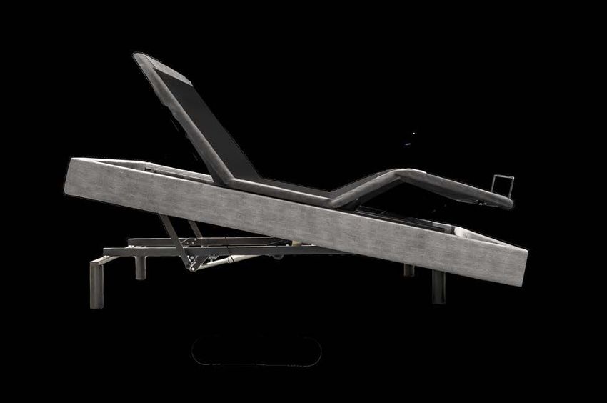
1 Carefully lift the base frame from the
shipping carton, keeping the unit top-
side-down. Remove the plastic wrapping
from the bottom to access the base.
To Control Box
2 Insert one end of the DC cord into the
power supply. Insert the other ends with
locking clips into the Control Box and USB
Charger cords. Lock the Control Box and
Locking Clips
USB Charger cords using the locking clips.
3 Insert the AC cord into the power supply.
IMPORTANT: DO NOT PLUG THE BASE
INTO THE AC OUTLET YET.
4 Insert the legs into the threaded holes
at each corner of the base by inserting
the leg and rotating clockwise until tight.
There must not be any gap or wobble
in the leg in order to avoid risk of injury
or damage to the base which may void
warranty.
Note: If setting two Twin XL’s bases to
use with one king size mattress, connect
the Sync cable to the control box (as
pictured) to one base. After bases are
arranged, connect the second Sync Cable
to other base’s control box.
6ASSEMBLY - BASE
5 Remove the Mattress Retainer Bar from
the bottom of the base. Finish removing
the plastic packaging from the base to
orient into final position. Carefully rotate
the base on its side, then lift and place on
legs.
IMPORTANT: DO NOT LEAN THE BED
AGAINST THE INSTALLED LEGS TO
TURN OVER.
6 Insert the Mattress Retainer Bar upright
as shown.
7 Replace the retainer clip securely.
7ASSEMBLY - BASE
REMOTE
8 Lift the battery cover and insert the
three AAA size batteries (included) into
+
READ USER MANUAL
BEFORE REMOVING
the remote as shown in the figure.
RE-LINK SWITCHES
UNDER LABEL
LABEL.
+
Replace the battery cover.
+ Remote is already linked with the base.
BASE POWER SUPPLY
9 Turn the power supply upside down to
access the battery cover, then slide the
battery cover off.
10 Insert the two 9V battery (included)
into the compartment and slide the
cover back on.
NOTE: The battery backup will allow
for the bed to be lowered if a power
outage occurs. It is not recommended
to do anything except lower the bed as
the battery backup will not last if the
features are continually used.
11 Insert AC plug into an AC outlet having
100-240V AC, 50/60Hz.
AC Plug AC Outlet
If attaching a headboard to the base, see the included instructions. Otherwise, place the
desired mattress onto the base and enjoy your new adjustable base!
8Assembly - Head Board Bracket
Headboard brackets may not be standard with purchase of adjustable base and can be
purchased separately.
IMPORTANT: The head board bracket must be assembled to the base AFTER the bed
base has been completely assembled. After assembling the bed according to the
owner’s manual, see this sheet to assemble the head board bracket.
Unpack the kit and make sure the following is included:
Bed Attachment Horizontal Shaft Head Board Attachment Plate M8x16mm Hex Bolt
PART A PART B PART C PART D
Qty: 8
Qty: 2 Qty: 2 Qty: 2
M8 Bolt M8 Nut Washer 10 Zinc Allen Key
PART E PART F PART G PART H
Qty: 4 Qty: 4 Qty: 4 Qty: 1
11 Completely
Completely
section
frame
raise raise
the head
headsection oftothe
of the bed
the
access
bed the
Fig. 1
toto whichthe
access theframe
headboard
to
bracket will mount.
which the headboard Identify the
two bracket
threadedwill holes that will be
mount.
usedIdentify
to mount bed attachment
the two thread-
( PartedA)holes
in Step #2.
that will be used
to mount bed attach-
ment ( Part A) in Step #2
acket
22 Line up the holes in the bed
attachment (Part A) with the
two threaded holes on the bed
Fig. 2 PART A
base. Insert two screws (Part
D) provided with the kit into
the threaded holes and tighten
with the Allen key (Part H)
provided with the kit.
PART D
9Assembly - Head Board Bracket
33 Attach the head
Attach
attachment
the horizontal
plate
boardboard
the head
attachment plate C) toC) Fig. 3
(Part (Part
shaft (Part B) PART G
PART C
to the horizontal shaft PART B
using(Part
the two flat head self
B) using the two flat PART F PART E
locking screws
head (Part E),screws
self locking two
washers
(Part E), two washers nuts
(Part G) and two (Part
(PartG)
F) and
provided with(Part
two nuts the kit.
F)
provided with the kit.
44
Insert, from the
Insert, from the outside of the
outside
bed, the of the
horizontal bed,
shaft (Part Fig. 4
B) intothe
thehorizontal shaft of
horizontal fitting PART B
the bed(Part B) into the
attachment (Part A).
horizontal fitting of
the bed attachment
(Part A).
PART A
5
Adjust the position of
the head board Fig. 5
5
PART C
Adjustattachment
the positionplates
of the (Part
head
boardC)attachment
to the right plates (Part
or the left
C) to the right or the left of the PART A
of the bed as desired by PART B
bed as desired by moving the
moving the horizontal
horizontal shaft (Part B) left
shaftin(Part
and right B) left and
the horizontal fitting
of theright in the horizontal
bed attachment (Part
fitting
A). Once of the bed
positioned correctly
tighten screws (Part
attachment D) to
(Part A).hold PART D
in place.
Once positioned
To adjust the position
correctly tighten of screws
the head board attachment plates (Part C) vertically, loosen
nuts and screws from step
(Part D) to hold in place. 3. Tighten when the appropriate height for your head
boardTo is adjust
met. the position of the head board attachment plates (Part C)
Install the head board using the line of 3 oval holes on the outside of the head board
vertically, loosen nuts and screws from step 3. Tighten when the
attachment plate.
appropriate height for your head board is met.
WARNING: The end of the horizontal shaft (Part B) must always extend beyond the
end ofInstall the headfitting
the horizontal board ofusing the
the bed line of 3 oval
attachment! holes
(Part on the
A) (See Fig. outside
5 Arrow)
of the head board attachment plate.
WARNING: The end of the horizontal shaft (Part B) must always
extend beyond the end of the horizontal fitting of the bed
attachment! (Part A) (See Fig. 5 Arrow)
10LOCATION OF CONTROLS - REMOTE
Foot Down
Head Up Elevate Up
Head Down Elevate Down
Foot Up Lay Flat
Anti-Snore
Zero-Gravity Position Position
Saved Position A Saved Position B
Length of Time for
Sleep Enhancement
Set Timer for Sleep
Enhancement/Turn Off All Torch Light
Sleep Enhancement Sleep Enhancement
Wave Up Intensity Up
Sleep Enhancement Sleep Enhancement
Wave Down Intensity Down
11OPERATION – MAIN
Press and hold the Head Up ( ) button
to raise the Head position. Release button
when desired position is reached.
Press and hold the Head Down ( ) button
to lower the Head position. Release button
when desired position is reached.
Press and hold the Foot Up ( ) button
to raise the foot position. Release button
when desired position is reached.
Press and hold the Foot Down ( ) button
to lower the foot position. Release button
when desired position is reached.
The patented Elevate feature allows the user even more customization of the sleeping position.
It allows the entire base to raise at an incline of up to 12 degrees. This lift feature can be used
in tandem or be operated separately from the head and foot incline. For example, the Elevate
feature can be used to tilt the base up while still in the flat position to help alleviate snoring
without inclining the head position up, or it can be used to place the base in a different viewing
position for television.
Press and hold the Elevate Up ( )
button to raise the entire base. Release
button when desired position is reached.
Press and hold the Elevate Down ( )
button to lower the entire base. Release
button when desired position is reached.
The Zero-Gravity position raises both the head
ZG and foot to a set position that distributes the
users weight so that it may provide a feeling
of weightlessness and possibly relieve stress
to the body. Press the Zero Gravity ( )
ZG
button and the Head/Foot positions will go
to the Zero Gravity position. This action can
be stopped at any time by pressing another
button.
12OPERATION – MAIN
The Anti-Snore position raises the head
ANTI
SNORE slightly so that it may allow relief to
snoring. Press the ANTI-SNORE ( ) button
ANTI
SNORE
and the Head position will go to the Anti-
Snore position. This action can be stopped at
any time by pressing another button.
Press the FLAT ( ) button and the bed
will level. This action can be stopped at
any time by pressing another button.
Press the MEMORY A ( ) or MEMORY B
( ) button and the Head/Feet positions
will go to the preset position. This preset
can be changed as shown later. This
action can be stopped at any time by
pressing another button.
Press and hold the Flashlight ( )
button and the remote will act as a mini
flashlight. Release the button and after a
few seconds, the flashlight will turn off.
Notes:
• When a button is pressed on remote,
all buttons will light to make it easier
to view in low light conditions.
• EMERGENCY LOWERING: If you
cannot find the remote control,
locate and press the red Emergency
Lowering button located on the main
control box on the bottom of the bed
(shown to the left).
13OPERATION – SLEEP ENHANCEMENT
Sleep Enhancement may help to ease the body to sleep and creates a white noise effect
through total body vibration.
1 Before starting a the total body vibration,
select the duration. To do this, repeatedly
press the TIMER/ALL OFF ( ) button to
select a duration; the respective Sleep
Enhancement LED (10MIN, 20MIN or
30MIN) will briefly light.
2 To start the total body vibration, press
the INTENSITY + ( ) button once. Press
up to three more times to increase the
massage intensity (up to four levels of
intensity). Press the INTENSITY – ( )
button to decrease the intensity.
3 There are 4 Wave modes available (Low,
Medium, High, and Constant). To increase
the Wave mode, press the WAVE + ( )
button once. Press up to three more times
to change the WAVE mode. It will increase
in order of Low, Medium, High, and
Constant. Press the WAVE - ( ) button
to lower the wave mode. Experiment with
different Wave and Intensity settings to
find what is most comfortable to you. The
higher the intensity, the more beneficial it
will be to your body.
4 The total body vibration will last for the
duration of time set in step 1. To turn off
the massage before the time is up, simply
press the TIMER/ALL OFF ( ) button.
14OPERATION - SETTING THE MEMORY PRESETS
To set the Memory A and/or Memory B
presets, perform the following steps:
1 Press the Flat (
is flat.
) button so the bed
2 Adjust the head and feet positions as
desired.
3 Press and hold the TIMER/ALL OFF ( )
button until the remote’s backlight starts
blinking (approximately three seconds),
then release the button.
4 Press the desired button to memorize:
MEMORY A ( ) or MEMORY B ( );
the backlight will stop blinking to confirm
that the memorizing was successful.
5 To restore the Memory Presets to
their factory positions, press and hold
the TIMER/ALL OFF ( ) button for
approximately six seconds; the remote’s
backlight will blink after three seconds,
and then turn off after another three
seconds to confirm that the remote
was reset.
15AVAILABLE ACCESSORIES
Item Part Number
18.5” High Profile Legs CBE2LEG18.5
To order an accessory, please call 1-800-428-5222.
16Linking the Remote
How do I link my remote control to the Comfort Base?
Connecting one Remote to one base
1 Press and hold the Link button (the black
round button on the control box located
on the bottom of the base) until the LED
light on the control box turns on and then
off. Release the button and the LED light
will blink.
2 Simultaneously press and hold the Head
Up and Foot Up buttons (the left button
and middle button located on the top row
of the remote) until the remote’s backlight
starts blinking. Release the two buttons
and the backlight and the LED light on the
control box will blink until linked, then they
will turn off.
3 Test the bed to make sure it is working,
and repeat the steps if it is not.
How do I Re-Program the Zero-Gravity button back to factory setting?
The Zero-Gravity button has the capability to be re-programmed. In case you would like to
set it back to the original Zero-Gravity setting follow the below instructions:
1. Raise Head to 17 degrees.
2. Raise Foot to 25 degrees.
3. Press and hold the program button labeled “TIMER/ALL OFF button” until the remote
starts to flash.
4. Release program button.
5. Press Zero Gravity button once.
6. Done.
Continued on the Next Page
17TROUBLESHOOTING
In the event the Comfort Base’s base fails to operate, investigate the symptoms and
possible solutions provided below:
Remote control • Unplug power cord, wait 30 seconds and plug in to reset
illuminates and appears electronic components.
to be operable, but no • Defective surge protection device or electrical outlet. Test
features of the base will outlet by plugging in another working appliance.
activate. • Electrical circuit breaker may be tripped. Check electrical
service breaker box to verify.
• Re-link the remote control (see Remote Control
Re-Linking section of this manual for programming
procedures).
Remote control will not • Replace batteries in the remote control.
illuminate.
Head, foot section • Base mechanism may be obstructed. Elevate base and
or Elevate will lift, check for obstruction. Remove obstruction.
but will not return to • Headboard may be too close to the edge of the mattress.
the horizontal (flat) Verify that the distance between headboard brackets and
position. mattress is sufficient. Adjust if necessary.
• If base is located on hard surface flooring, place carpet
Excessive massage pieces or rubber cups under each leg of the base.
motor noise. • Verify that the base is not positioned against a wall,
nightstand, or other object that may cause vibration or
noise.
• If base is installed inside a wood bed frame, verify
vibe motor is not causing bed frame (or bed frame
components) to vibrate.
• Verify that headboard attachment hardware is tightened
firmly (if used).
Continued on the Next Page
18TROUBLESHOOTING
Head, Foot or Elevate • Check batteries in remote; replace if necessary.
Function has minor • Make sure that you are following the duty cycle of the
interference during motor (do not operate more than one (1) minute over
operation. an eight (8) minute period, or approximately a 12% duty
cycle).
• Press the lift buttons squarely and accurately.
• Control box may be experiencing common radio frequency
interference from other radio transmitting devices (see
Remote Control Re-Linking section).
The remote is causing • Lift the battery cover on remote and remove the yellow
interference with sticker to expose the DIP switches. Slide the switches
appliances, TV, garage to different positions. See page 17 for remote re-linking
door opener, another instructions.
base in a different
room, etc.
19SPECIFICATIONS
Weight Capacity ......................................................................................................... Queen: 600 lb
................................................................ Twin/XL: 400 lb (800 lb if using two twins as a King)
Power Input .................................................................................................. AC100-240 50/60HZ
Power Transformer Output......................................................................................... DC29V 1.8A
Radio Frequency ......................................................................................................................2.4 GHZ
Overall Height of Bed .......................................................................................................... 15 inches
Elevate Incline ..................................................................................................................................12°
Incline............................................................................................................Head - 65°, Feet - 40°
Included Accessories ....................... Sync Cable (Twin XL size only), Mattress Retainer Bar,
.......................................................... Headboard Bracket Kit, Remote Control, Power Supplies,
................................................ AC and DC Power Cords, (2) 9V Batteries for Battery Backup,
...................................................................................... (3) AAA Batteries for Remote, (1) Manual
TECHNICAL ASSISTANCE
For any questions, claims, or technical assistance, please contact Glideaway at
1-855-581-3095 or comfortbase@glideaway.com.
SERVICE REQUIREMENTS
Service technicians are not responsible for moving furniture, removing headboards and
foot boards, or any items required to perform maintenance on your adjustable bed. In the
event the technician is unable to perform service due to lack of accessibility, the service
call may be billed to the purchaser and the service will be re-scheduled.
CLEANING
Spot clean with upholstery shampoo, foam from a mild detergent, or mild dry cleaning
solvent. Pre-test a small inconspicuous area before proceeding. Do not saturate. Pile
fabrics may require brushing with a non-metallic bristle brush. Hot water extraction or
steam cleaning is not a recommended cleaning method.
20WARRANTY
Glideaway Comfort Base® Twenty Year Limited Warranty 1022.C
Glideaway Sleep Products (“Glideaway”) warrants to the original consumer purchaser that the motorized bed frame, motorized bed
foundation and adjustable bed (hereinafter referred to as “adjustable bed” or “adjustable beds”) are free from defects in workmanship
and material as provided herein. To the extent permitted by law, this Limited Warranty is not transferable and coverage terminates if the
original consumer purchaser (“purchaser”) sells or otherwise transfers the product.
If you wish to make a claim
You must contact the Glideaway dealer from whom the product was purchased, or if not available, Glideaway 1 855 581-3095 within
thirty days of discovery of the problem with the serial number and the original sale receipt which identifies the date of purchase. Any
information or materials to be returned upon authorization should be sent to Glideaway at 8226 Lackland Road, St. Louis, MO 63114.
What we will do
Year 1: Full coverage parts and labor warranty This adjustable bed is warranted against defects in the workmanship or materials for
a period of up to one (1) year from the date of purchase for adjustable beds bought new and for up to one (1) year from the date of
manufacture for those beds that were originally floor samples. Glideaway will send replacement parts (at no cost to the purchaser) for
any defective adjustable bed part to the purchaser, and Glideaway will pay all pre-authorized labor and transportation costs associated
with the repair or replacement of any parts which Glideaway determines to be defective. This one (1) year warranty shall not apply if
purchaser does not return any and all defective parts to Glideaway within 15 days of purchaser’s receiving of replacement part(s).
Years 2 and 3: Full coverage of parts only warranty If the defect occurs in the second or third year following purchase for
adjustable beds bought new and following the date of manufacture for adjustable beds that were originally floor samples, Glideaway
will offer replacement parts (upon terms and conditions set forth in this paragraph) for any mechanical adjustable bed part found to be
defective or malfunctioning. This limited warranty shall not apply if purchaser does not return any and all defective or malfunctioning
parts to Glideaway within 15 days of purchaser’s receipt of replacement parts. To the extent permitted by law, the purchaser shall
bear all service, transportation, labor, shipping and handling costs related to the delivery and/or replacement of the defective or
malfunctioning parts.
Years 4 through 20: Prorated coverage of non-electrical parts only warranty If the defect occurs in the fourth through
twentieth year following purchase for adjustable beds bought new and following the date of manufacture for adjustable beds that
were originally floor samples, Glideaway will offer replacement parts (upon terms and conditions set forth below) for any mechanical
adjustable bed part found to be defective or malfunctioning. Electronics, electrical components, massage motors and lift motors are
excluded. Purchaser shall pay 1/17th of the then current replacement cost of the defective part multiplied by the number of years past
the third year the purchaser has owned the adjustable bed for those beds bought new or multiplied by the number of years past the
third year the purchaser has owned the adjustable bed since the adjustable bed was manufactured for those adjustable beds which were
floor samples. Glideaway shall bear the remainder of the cost of the replacement part. This limited warranty shall not apply if purchaser
does not return any and all defective parts to Glideaway within 15 days of purchaser’s receipt of replacement parts. To the extent
permitted by law, the purchaser shall bear all service, transportation, labor, shipping and handling costs related to the delivery and/or
replacement of the defective or malfunctioning parts.
This limited warranty does not cover or apply to
This Limited Warranty does not apply: (a) to any damage caused to the adjustable bed by the purchaser; (b) if there has been any
unauthorized repair or replacement of the adjustable bed or parts; (c) if the adjustable bed has been mishandled whether in transit or
by other means, subjected to physical or electrical abuse or misuse, or otherwise operated in any way inconsistent with the operation
and maintenance procedures outlined in the Owner’s Manual, this limited warranty, and any other applicable document published or
approved by Glideaway; (d) in relation to damage to mattresses, fabric, cables, electrical cords or items supplied by dealers (also known
as retailers or resellers); (e) if there has been any unnecessary service calls, including costs for inhome service calls solely for the purpose
of educating the purchaser about the adjustable bed and/or for finding an unsatisfactory power connection; (f) if the recommended
weight restrictions (Twin/TXL/Split Queen/Split CA King: 400 pounds/ 181 kilograms, Full/FXL: 500 Pounds/ 227 kilograms, Queen:
600 Pounds/ 272 kilograms) and guidelines for proper distribution of weight as stated in the Owner’s Manual are not followed; (g) for
adjustable beds used in commercial type settings, such as but not limited to dormitories, hotels and rentals.
Additional terms and conditions
No reimbursement will be made to the purchaser for the inconvenience, removal, installation, setup time, lack of use, shipping, or any
other costs or expenses not covered by this limited warranty. Glideaway holds no responsibility for in-home service on adjustable beds.
Purchaser should contact their dealer for any terms and conditions relating to purchaser’s in-home service if any.
Removal of product tag shall void warranty. The product tag has both the model and serial numbers, which serves as a means of
identification to establish one’s warranty rights. It is attached to the metal substructure visible when one lifts the head of the base.
TO THE EXTENT PERMITTED BY APPLICABLE LAW, THIS LIMITED WARRANTY REPLACES ALL OTHER REPRESENTATIONS, WARRANTIES
OR CONDITIONS, WHETHER EXPRESSED, IMPLIED OR LEGAL, ARISING FROM STATUTE COURSE OF DEALING, USAGE OF TRADE OR
OTHERWISE INCLUDING ANY IMPLIED WARRANTIES OR CONDITIONS OF MERCHANTABILITY, DURABILITY, QUALITY AND FITNESS
FOR A PARTICULAR PURPOSE AND NO ONE IS AUTHORIZED TO ASSUME OR UNDERTAKE FOR GLIDEAWAY OTHER LIABILITY IN
CONNECTION WITH THE SALE OF THE PRODUCT. GLIDEAWAY SHALL NOT BE LIABLE FOR ANY DAMAGES, WHETHER DIRECT,
INDIRECT OR CONSEQUENTIAL OR ANY OTHER DAMAGES OF WHATEVER KIND, INCLUDING PERSONAL INJURIES OR DAMAGE TO
PROPERTY, EXCEPT AS PROVIDED HEREIN.
This warranty is made by Glideaway and is not made by or on behalf of its distributors, retailers or any other party. Some states or
provinces do not allow the exclusion or limitation of incidental or consequential damages or the exclusion of implied warranties or the
limitation on how long an implied warranty lasts, so the above limitations or exclusions may not apply to you. This warranty gives you
specific legal rights, and you may also have other rights which vary from state to state or province to province. To the extent that the
provisions of any applicable legislation expressly replaced, eliminate, amend, extend or prohibit any term or terms contained in this
warranty, such term or terms shall be accordingly replaced, eliminated, amended or extended, as the case may be, in accordance with
such legislation.
21REGISTRATION
Thank you for purchasing a Comfort Base!
Register your Comfort Base by completing the form below or registering online at
www.glideaway.com
Warranty Service
Filling out this form will help you obtain more efficient warranty service in case there is a
problem with your product.
Confirmation of Ownership
In case of an insurance loss such as fire, flood, or theft, your registration could serve as
your proof of purchase.
For Your Safety
Registering your Comfort Base will allow us to contact you in the unlikely event a safety
notification is required.
Please mail the form and send with a copy of your proof of purchase to:
Glideaway
Attn: Warranty/Claims Department
8226 Lackland Drive
St. Louis, MO 63114
Customer Info:
First Name: ___________________________________________________________
Last Name: __________________________________________________________
Address: _____________________________________________________________
City: ________________________________________________________________
State: __________________________________ Zip: _________________________
Email: _______________________________________________________________
Phone Number: ______________________________________________________
Date of Birth: _________________________________________________________
Purchase Info:
Date of Purchase: ________________ Model Number: ______________________
Serial Number: _______________________________________________________
Did you buy online? Yes ____ No _____
Name of Retailer You Purchased From: ___________________________________
City of Retailer: ________________ State of Retailer: ____________________
Size of Base: ___________________ Price Paid: ____________________
22Contenido
Información de Seguridad ...........................................................24
¿Qué está incluido?.......................................................................27
Ensamblaje - Base .........................................................................28
Ensamblaje - Soporte del Cabecero .........................................31
Ubicación de los controles - Control Remoto ........................33
Funcionamiento - Principal .........................................................34
Funcionamiento - Mejora del sueño.........................................36
Funcionamiento - Configuración de la Memoria
Preprogramada ...............................................................................37
Accesorios Disponibles.................................................................38
Vincular el Control Remoto .........................................................39
Resolución de Problemas .............................................................40
Especificaciones .............................................................................42
Soporte Técnico .............................................................................42
Servicio ............................................................................................42
Limpieza ...........................................................................................42
Garantía............................................................................................43
Registro ............................................................................................44
Información para el Usuario
Tómese unos minutos y anote el número de serie en el espacio provisto a continuación, en
caso de que lo necesite en el futuro. Encontrará esta información levantando la cabecera
de la cama.
SKU: CBE2ASC
Serial Number ________________________________________________________
Número de Serie ______________________________________________________
Necesitará este número para solicitar en el futuros servicio técnico.
23INFORMACIÓN DE SEGURIDAD
ATENCIÓN
INSTRUCCIONES IMPORTANTES DE SEGURIDAD. CONSERVE ESTE
MANUAL LEA DETENIDAMENTE ESTAS INSTRUCCIONES ANTES
DE UTILIZAR ESTE PRODUCTO. EL USO CORRECTO DE SU CAMA
REGULABLE ES NECESARIO PARA GARANTIZAR LA RESISTENCIA
Y DURABILIDAD QUE USTED ESPERA DE UN PRODUCTO DE ALTA
CALIDAD. EL FABRICANTE HA PROBADO E INSPECCIONADO ESTE
PRODUCTO ANTES DEL ENVÍO.
LA FRECUENCIA DE RADIO ES 2.4 GHZ.
Este aparato cumple con la sección 15 de las normas de la FCC.
El funcionamiento está sujeto a las dos condiciones que figuran a continuación:
(1) Este aparato probablemente no provoque interferencia perjudicial y
(2) Este aparato aceptará cualquier interferencia que reciba, incluyendo la interferencia que pueda
causar un funcionamiento no deseado.
Los cambios a la antena o al aparato pueden ocasionar que el aparato exceda los requerimientos de
exposición a RF y anular el derecho del usuario a operar el aparato.
El voltaje de entrada es AC100-240 50/60HZ; el voltaje de salida es DC29V 1.8A.
SEGURIDAD ELÉCTRICA
Siempre desenchufe esta cama regulable del tomacorriente antes de realizar trabajos de
limpieza o mantenimiento de la cama. Para desconectar de manera segura, quite el enchufe
del tomacorriente.
Evite el contacto del cable con superficies calientes. Utilice solo en interiores.
. ADVERTENCIA: PARA EVITAR INCENDIOS O PELIGROS DE DESCARGA, NO EXPONGA ESTA
UNIDAD A LA HUMEDAD.
Suspenda el uso de esta cama regulable y comuníquese con el fabricante para su
reparación si: (1) un cable o enchufe está dañado, (2) no funciona correctamente, (3) se
cayó o se dañó.
PARA UNA SEGURIDAD ÓPTIMA, LE ACONSEJAMOS QUE ENCHUFE SU CAMA REGULABLE
A UN PROTECTOR DE SOBREVOLTAJE (el cual no se incluye con esta cama regulable)
PRECAUCIONES CON LAS PILAS
Tenga en cuenta estas precauciones cuando utilice pilas con este dispositivo:
1. Advertencia - Peligro de explosión si la pila se reemplaza incorrectamente. Reemplace
únicamente con las pilas 6LR61 de 9V y las pilas LR03 AAA.
2. Asegúrese de respetar la polaridad correcta cuando coloque las pilas, tal como se indica
en el compartimiento de las mismas. Si coloca las pilas al revés, el dispositivo se puede
dañar.
3. No mezcle diferentes tipos de pilas (por ejemplo alcalinas, recargables y de zinc-carbono)
o pilas viejas con nuevas.
4. Si el dispositivo no se utiliza por un largo período de tiempo, quite las pilas para prevenir
daños o lesiones debido a una posible pérdida de las mismas.
5. No intente recargar pilas que no fueron diseñadas para ese fin; pueden recalentarse y
romperse. (Siga las instrucciones del fabricante de las pilas.)
24INFORMACIÓN DE SEGURIDAD
ADVERTENCIA DE GARANTÍA
Esta cama está específicamente diseñada para no requerir mantenimiento de su parte,
el usuario. No abra ni manipule indebidamente la caja de control, motores o controles
manuales (con excepción del compartimiento de las pilas, si estuviera equipado) dado
que ello anulará la garantía. No intente alterar el cableado de los componentes o ajustar o
modificar la estructura del producto de manera alguna dado que ello anulará la garantía.
Solo quienes estén autorizados podrán realizar trabajos de reparación o reemplazo de
piezas en su cama regulable.
SOLO PARA USO HOGAREÑO
Esta cama regulable está diseñada exclusivamente para uso hogareño.
EXENCIÓN DE RESPONSABILIDAD MÉDICA/ DE HOSPITALES: Esta base NO está
diseñada para uso médico u hospitalario (En el hogar o Comercial) y NO está diseñada
para cumplir con los estándares del hospital o médicos. No utilice esta base con equipos de
oxigenoterapia por carpa ni cerca de gases explosivos.
USUARIOS CON MARCAPASOS
Es posible que la funcionalidad vibratoria de esta cama sea interpretada en falso por
algunos marcapasos como movimiento y/o ejercicio. Esto es común con todo producto que
produzca un movimiento vibratorio, y puede afectar o no su marcapasos. Consulte a su
médico si tiene inquietudes al respecto.
CLASIFICACIONES DEL PRODUCTO
Restricciones de los motores de elevación: Los motores de elevación de esta cama NO
están diseñados para funcionar de manera continua por más de un (1) minuto a lo largo
de un período de ocho (8) minutos, o aproximadamente un ciclo de trabajo del 12%. Para
garantizar un funcionamiento confiable y la vida plena de este producto, no intente exceder
estos límites.
NOTA: Intentar evadir o exceder esta clasificación acortará la vida útil
del producto y podría anular la garantía.
Restricciones de Peso: Los límites de peso recomendado para nuestras camas regulables son:
Queen: 600 libras 2 Plazas/XL: 500 libras 1 Plaza/XL: 400 libas (800 libras si se utilizan
dos camas de 1 plaza como una King)
La estructura de la cama soportará el peso recomendado cuando el mismo esté distribuido
uniformemente en toda la cama.
La cabecera y pie de cama no están diseñados para soportar o levantar
individualmente este peso.
Para un rendimiento e integridad óptimos de la estructura, se recomienda subirse y bajarse
de la cama regulable con la cama en posición horizontal.
NOTA: Exceder las restricciones de peso recomendado podría dañar su cama
regulable y anular su garantía.
Restricciones de los Motores de Vibración:
Los motores de vibración no están diseñados para un funcionamiento continuo y prolongado.
Los sistemas del motor de vibración están clasificados para un máximo de dos horas de uso
dentro de un período de 6 horas. El motor de vibración emitirá un tono mínimo cuando esté
en funcionamiento. Esto es normal. A medida que se aumente el nivel del motor de vibración,
se intensificará la resonancia del motor.
25INFORMACIÓN DE SEGURIDAD
ADVERTENCIA PARA NIÑOS PEQUEÑOS Y MASCOTAS
Deseche inmediatamente todos los materiales del embalaje puesto que pueden presentar
riesgo de asfixia para niños pequeños y mascotas. Si permite que niños o mascotas jueguen
sobre o debajo de la cama, pueden resultar heridos. No permita que los niños operen esta
cama sin la supervisión de un adulto.
LUBRICACIÓN Y LIMPIEZA
Este producto está diseñado para no requerir mantenimiento. Los motores de elevación se
encuentran permanentemente lubricados y sellados -no se requiere lubricación adicional.
No aplique lubricante en los tornillos madre del motor de elevación o en las tuercas de
nylon, ya que la base podría deslizarse accidentalmente hacia abajo desde la posición
elevada.
ADVERTENCIA DE ELEVACIÓN
NO SE SIENTE SOBRE LA CABECERA O PIE DE CAMA CUANDO ÉSTA ESTÉ EN
POSICIÓN ELEVADA O DURANTE LA ELEVACIÓN O DESCENSO.
LUGAR DE USO
El nivel de sonido experimentado durante el funcionamiento está directamente relacionado
con el lugar donde esté ubicada la unidad Por ejemplo, cuando una base se encuentra
ubicada sobre un piso madera con la función de vibración activada, se escuchará un tono
de vibración. Para minimizar esta resonancia, coloque un pedazo de alfombra debajo de
cada pata de la base.
Es posible que se experimente vibración o ruido desde los soportes de los cabeceros, los
cabeceros o pieceros si los tornillos de montaje no están ajustados firmemente.
TRASLADO DESPUÉS DE LA INSTALACIÓN
No coloque la base de la cama regulable en posición vertical sobre su cabecera o pie. Ello
podría ocasionar lesiones a personas o dañar la base.
ADVERTENCIA
Para disminuir el riesgo de quemaduras, incendio, descarga eléctrica o lesión a personas::
• Desenchufe del tomacorriente antes de colocar o retirar accesorios.
• Se requiere supervisión de cerca cuando esta base sea utilizada por niños, personas
enfermas, personas con discapacidades o mascotas, o cerca de ellos.
• Utilice esta base sólo para su uso previsto, tal como se describe en estas instrucciones.
No utilice complementos no recomendados por el fabricante.
• Nunca opere esta base si un cable o enchufe está dañado, no funciona correctamente, se
cayó o dañó, o se cayó al agua.
• Evite el contacto del cable con superficies calientes.
• Nunca deje caer ni inserte objetos en ninguna abertura.
• No utilice la unidad en exteriores.
• No opere la unidad donde se estén utilizando productos de aerosol o donde se esté
administrando oxígeno.
• Para desconectar, retire el enchufe del tomacorriente.
• NO UTILICE CERCA DE PERSONAS QUE ESTÉN UTILIZANDO DISPOSITIVOS MÉDICOS.
SOLO PARA USO DOMÉSTICO/RESIDENCIAL.
26¿QUÉ ESTÁ INCLUIDO?
Antes de descartar los materiales de embalaje, revise la caja de envío de la base regulable y
verifique que se hayan incluido los siguientes artículos:
(1) Base
(1) Sujetador de colchón en la piecera
(adherido a la base)
(4) Patas
(1) Control Remoto
(1) Cable de CA (no adherido a la base)
(1) Alimentación
(no adherido a la base)
(1) Cable de Alimentación de CC
(1) Cable de sincronización
(solo para camas de 1 plaza XL)
(1) Kit de Soporte del Cabecero
También se Incluye:
(3) Pilas AAA
(2) Pilas de 9V
(1) Manual
27ENSAMBLAJE - BASE
Es ALTAMENTE recomendado que dos personas realicen la instalación de este producto.
Para ensamblar, siga los pasos que se describen a continuación:
1 Levante cuidadosamente la base de la
caja de envío, manteniendo la unidad con
la parte superior hacia abajo. Retire el
envoltorio de plástico de la parte inferior
para acceder a la base.
A la caja de control
2 Introduzca un extremo del cable de CC en
la fuente de energía. Introduzca los otros
extremos que tienen llaves de bloqueo
Llaves de bloqueo
en la Caja de Control y en los cables del
cargador USB. Bloquee la Caja de Control
y los cables del cargador USB utilizando
las llaves de bloqueo.
3 Introduzca el cable de CA en la fuente de
energía.
IMPORTANTE: TODAVÍA NO ENCHUFE
LA BASE EN EL TOMACORRIENTE DE
CA.
4 Introduzca las patas en los orificios
roscados en cada esquina de la base,
insertando la pata y girando en el sentido
de las agujas del reloj hasta que esté bien
ajustada. No debe haber ningún espacio o
bamboleo en las patas para evitar el riesgo
de lesiones o daños a la base que puede
anular la garantía.
Nota: Si está instalando dos bases
de 1 plaza XL para utilizar con un
colchón tamaño King, conecte el cable
de sincronización a la caja de control
(como se muestra en el dibujo) de una
de las bases. Después de colocar las
bases, conecte el segundo cable de
sincronización a la caja de control de la
otra base.
28ENSAMBLAJE - BASE
5 Retire la barra sujetadora del colchón de
la parte inferior de la base. Termine de
remover el embalaje plástico de la base
para orientarlo a la posición final. Con
cuidado, gire la base sobre el costado,
luego levante y coloque sobre las patas.
IMPORTANTE: NO APOYE LA CAMA
SOBRE LAS PATAS INSTALADAS PARA
DARLA VUELTA.
6 Inserte la barra sujetadora del colchón en
posición vertical como se muestra.
7 Vuelva a colocar el gancho de retención
firmemente.
29ENSAMBLAJE - BASE
CONTROL REMOTO
8 Levante la tapa del compartimiento
de las pilas y coloque las tres pilas
+
READ USER MANUAL
BEFORE REMOVING
tamaño AAA (incluidas) en el control
RE-LINK SWITCHES
UNDER LABEL
LABEL.
+
remoto, tal como se muestra en la
figura. Vuelva a colocar la tapa de dicho
+ compartimiento.
El control remoto ya está enlazado con
la base.
FUENTE DE ENERGÍA DE LA BASE
9 Dé vuelta la fuente de energía para
acceder a la tapa del compartimiento
de las pilas y luego deslice para retirar
la tapa.
10 Coloque las dos pilas de 9V (incluidas)
en el compartimiento y deslice la tapa
para volver a colocarla..
NOTA: La reserva de energía permitirá
que la cama pueda bajarse si ocurre un
corte de electricidad. No se recomienda
hacer otra cosa más que bajar la cama
puesto que la reserva de energía no
durará si se siguen utilizando el resto de
las funciones.
11 Introduzca el enchufe de CA en un
tomacorriente de CA que tenga 100-
240V CA, 50/60Hz.
Enchufe de CA Tomacorriente
de CA
Si desea fijar un cabecero en la base, remítase a las instrucciones. Caso contrario, coloque
el colchón sobre la base y ¡disfrute de su nueva base regulable!
30Ensamblaje - Soporte del Cabecero
Los soportes del cabecero tal vez no sean compatibles con la base ajustable y pueden
comprarse por separado.
IMPORTANTE: El soporte de cabecero debe ensamblarse con la base LUEGO de haber
ensamblado completamente la base de la cama. Después de ensamblar la cama según el
manual del usuario, consulte esta hoja para ensamblar el soporte del cabecero.
Desembale el kit y asegúrese de que esté incluido lo siguiente:
Tornillo hexagonal
Sujeción de la cama
Bed Attachment Eje horizontal
Horizontal Shaft Placa
Headde sujeción
Board del cabecero
Attachment Plate M8x16mm
M8x16mm Hex Bolt
Parte
PART A A Parte
PART B B Parte
PART C C Parte
PART D C
Qty: 8
Qty: 2
Cantidad 2 Qty: 2
Cantidad 2 Qty: 2
Cantidad 2 Cantidad 2
Tornillo
M8 Bolt M8 Tuerca
M8 NutM8 Arandela
Washer 10de cinc 10
Zinc llaveKey
Allen Allen
PART E PART F PART G PART H
Parte
Qty: 4 E Parte
Qty: 4 F Parte
Qty: 4 G Parte
Qty: 1 H
Cantidad 4 Cantidad 4 Cantidad 4 Cantidad 1
11 Levante
camato
completamente
Completely
sección
headsection
para acceder
access
raise thela
de la cabeza de labed
of the
al marco
the frame to
Fig. 1
al cualwhich
se montará el soporte
the headboard
del cabecero. Identifique
bracket will mount. los
dos orificios
Identifyroscados que
the two thread-
se usarán parathat
ed holes montar
will la
be used
sujeción de la cama
to mount (Parte A)
bed attach-
en el ment
paso 2.
( Part A) in Step #2
acket
22
PARTE
PART AA
Alinee los orificios en la Fig. 2
sujeción de la cama (Parte
A) con los dos orificios
roscados de la base de la
cama. Introduzca dos tornillos
(Parte D) que vienen con el
kit en los orificios roscados y
ajuste con la llave Allen (Parte PARTE
PART DD
H) que viene con el kit.
31Ensamblaje
ssembly -- Head
Soporte del Bracket
Board Cabecero
3Adhiera la placa de sujeción
del cabecero (Parte C) al eje
horizontal (Parte B) usando los
)
Fig. 3
PARTE
PART GG
PARTE
PART CC
PARTE
PART BB
dos tornillos de autobloqueo PARTE PARTE
PART EE
t PART FF
del cabezal (Parte E), dos
s
arandelas (Parte G) y dos
art
tuercas (Parte F) que vienen
con el kit
4 Introduzca, desde afuera de la
cama, el eje horizontal (Parte
B) en la colocación horizontal
Fig. 4
PART B
de la sujeción de la cama
(Parte A).
PARTE
PART AA
djust the position of
Fig. 5
PARTE
PART CC
art
t or the left
5 Ajuste la posición de las placas
de sujeción del cabecero (Partey
C) a la derecha o izquierda tal
PARTE
PART AA
PARTE
PART BB
de la cama según desee,
moviendo el eje horizontal tal
(Parte B) a la derecha e
izquierda en la colocación PARTE
PART DD
horizontal de la sujeción de
la cama (Parte A). Una vez posicionado correctamente, ajuste los tornillos (Parte
D) para mantenerlo en su lugar. Para ajustar la posición de las placas de sujeción del
cabecero (Parte C) en forma vertical, afloje las tuercas y tornillos del paso 3. Ajuste
cuando se alcance la altura adecuada para su cabecero. Instale el cabecero utilizando
la línea de 3 orificios ovalados en la parte exterior de la placa de sujeción del cabecero.
ADVERTENCIA: El extremo del eje horizontal (Parte B) debe siempre extenderse más
allá del extremo de la colocación horizontal de la sujeción de la cama (Parte A) (Ver la
Fig. 5).
32UBICACIÓN DE LOS CONTROLES-CONTROL REMOTO
Bajar pies
Levantar cabeza Elevar hacia arriba
Bajar cabeza
Elevar hacia abajo
Levantar pies Horizontal
Posición Anti-
Posición Gravedad Cero ronquido
Posición A guardada Posición B guardada
Duración para
mejora del sueño
Fijar Temporizador para
mejora del sueño - Apagar
todos Linterna
Subir Onda de Aumentar Intensidad de
mejora del sueño mejora del sueño
Bajar Onda de Reducir Intensidad
mejora del sueño de mejora del sueño
33FUNCIONAMIENTO - PRINCIPAL
Oprima y mantenga presionado el botón
Levantar cabeza ( ) para levantar la
posición de la cabeza Suelte el botón
cuando llegue a la posición deseada.
Oprima y mantenga presionado el botón
Bajar cabeza ( ) para bajar la posición de
la cabeza Suelte el botón cuando llegue a la
posición deseada.
Oprima y mantenga presionado el botón
Levantar pies ( ) para levantar la posición
de los pies. Suelte el botón cuando llegue a
la posición deseada.
Oprima y mantenga presionado el botón
Bajar pies ( ) para bajar la posición de
los pies. Suelte el botón cuando llegue a la
posición deseada.
La función patentada Elevate (Elevar) permite al usuario una mejor personalización de la posición
para dormir. Permite que toda la base se eleve a una inclinación de hasta 12 grados. Esta función
de elevación se puede usar en grupo o bien se pueden operar por separado la inclinación de la
cabeza y la de los pies. Por ejemplo, la función Elevate (Elevar) se puede usar para inclinar la base
hacia arriba mientras aún se encuentra en posición horizontal para ayudar a aliviar el ronquido sin
inclinar la posición de la cabeza hacia arriba, o se puede usar para colocar la base en una posición de
visualización diferente para ver la televisión.
Oprima y mantenga presionado el botón
Elevar hacia arriba ( ) Suelte el botón
cuando llegue a la posición deseada.
Oprima y mantenga presionado el botón
Elevar hacia abajo ( ) para bajar toda la
base. Suelte el botón cuando llegue a la
posición deseada.
La posición de Gravedad cero (Zero-Gravity)
eleva los pies y la cabeza hasta una posición
ZG establecida que distribuye el peso de los
usuarios de forma tal que puede proporcionar
una sensación de ingravidez y posiblemente
alivie el estrés del cuerpo. Presione el botón
Gravedad Cero ( ) para que la posición de
ZG
cabeza y pies pase a la posición de Gravedad
Cero. Esta acción puede detenerse en
cualquier momento presionando otro botón.
34You can also read


