Volkswagen Golf GTI MK6 2010 - Fitment Guide
←
→
Page content transcription
If your browser does not render page correctly, please read the page content below
Fitment Guide
Volkswagen Golf GTI MK6 2010
                                                   V1.0

                                       www.ecliptech.com.au

You need 3 wires to fit the Shift-I to the GTI. Power and Ground from the diagnostics port (near
driver’s side knee) and the RPM signal from the engine bay. I’ve included a heap of pictures,
stepping through the installation. Use this guide at your own risk.

This is fitted to a right hand drive vehicle. Routing of a left hand drive car would be a little more
straight forward.

First step is to install the RPM wire. I started in the passenger foot well. Poking one end of the wire
through to the engine bay, and the other end through the centre console to the driver’s side.

  RPM wire will
  come from the                                                                         Liner was easy to
  engine bay (top                                                                       put back.
  left corner of
  foot well), and                                                                       However when
  travel to the                                                                         you put the
  right, through                                                                        screws in, get
  the centre                                                                            your head in there
  console.                                                                              with a torch.

  Unscrew these                                                                         Make sure to
  by hand.                                                                              screw them in at
                                                                                        the right angle to
                                                                                        look after the
  Pull the top liner                                                                    screw thread.
  mat out.

 Picture shows                                                                           Cables
 top left of foot
 well (behind
 liner mat),                                                                             Cable hole
 looking up.

 RPM wire is                                                                             You will need an
 threaded                                                                                extra 3m of wire
 through this                                                                            for this RPM
 cable grommet,                                                                          connection. Ask
 into the engine                                                                         Ecliptech for
 bay.                                                                                    some when
                                                                                         ordering.
No easy to poke
the wire through
the grommet, so
I taped it to a
short skewer.
Doesn’t need to
be very long.
I snapped the
sharp tip off, as
preferred to use
a very blunt tip.
Cable hole.
This is the view
RPM wire that
in the engine
was fed
bay, just behind
through.
the battery.
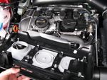
The RPM wire is The engine post
going to one of positions are
the coil packs, circled for
which is under reference.
the engine
cover. When you later
put it back on,
Pull the engine pop all four into
cover off place.
(vertically up).
It has four posts
that sit in rubber
grommets that
holds it on.The wiring is This cover snaps
held in place back on very
with a plastic cleanly. Just
cover. Need to make sure when
take this off to you fit it back on,
get easy access that the cover sits
to the wires over the coil pack
inside. plug.
Start at one
end. Push the
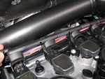
retaining tabs in Coil packs.
one at a time
while levering
the cover off.
If you don’t have Route the wire
cable ties, ask from behind the
Ecliptech to battery, under
pack some in for the duct and to
you when the closest coil.
ordering.
Cable tie at
short intervals.
Need little bit of
slack between
cable tie points,
but not enough
for the wire to
swing around.
Connect the RPM The Shift-I comes
wire to the with wire snap on
PURPLE/YELLOW clips, but you’re
wire. best to solder this
join as I don’t think
It’s a thin wire, the clip would fit
which goes to that under the wiring
first coil pack. cover.
Tape the join up.Back to the
passenger foot The bolt to take
well. the panel off is a
T20 torx bit
I took the side (typical six point
panel off to feed spline type).
the wire through
the centre I used a skewer
console. You to feed the wire
might be able to through. If you
blindly poke it have some light
through without from the other
having to side, it’s easy to
remove the see where to
panel. feed through.
Plenty of space.
RPM wire
through to drivers
side.
I cable tied it up
higher (above red
dashed line), out
of sight, then run
it in front of the
pedals (to avoid
the mechanisms).
Then cable tied
over on the right
side.
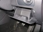
Remove the Squeeze sides in, and drop
drawer. drawer to a lower position.
Pull off hingesLower the This starts to
steering wheel pull the trim out
(tilted down) for of the clips.
better access.
Now pull the
I used a flat trim towards you
screw driver to to dislodge it
pry one side of from the clips.
the trim out.
Came out easier
than I’d
expected.
Didn’t mark.
Trim dislodged.
Feed the
Shift-I’s wire
through.Feed the
wires further
down, towards
the
diagnostics
connector.
Cable tie
these wires to
the nearby
cable bundle.
Shift-I’s wire. Torx bolt
holding
diagnostics
connector
bracket in
place.
Diagnostics
Connector
I removed the Don’t confuse this
diagnostics connectors
connector from the black/blue with the
mounting bracket Shift-I’s black/blue
so I could get a RPM wire.
clear photo.
You could use the
You can access red snap on clips
the wires without that the Shift-I comes
doing this. with here.
Connect the Shift- Join the RPM wire
I’s Black wire to you have feed
the connectors through from the
Brown wire. engine bay to the
There are two Shift-I’s Black/Blue
brown wires, both wire. If you get the
are ground. extra wire from
Ecliptech, they’ll fit
Connect the Shift- bullet terminals so
I’s Black/Red to these two can just be
the connectors connected. Insulate
Black/Blue. any joins.Fit the adhesive
strip (included) to Probably best
the bottom rear to not fully
edges of the Shift-I. push the trim in
until you get it
When you push the positioned just
trim back in place, how you want
you will sandwich it. Then snap
the Shift-I’s wires in into place.
place, which
anchors it nicely in
position.
Fits the dash area
really well. Looks
OEM.
I set the Calibration
to 0.5 and the
Sensitivity to 4.
I have the first light
set to turn on at
2,200rpm, and
finish at 6,000rpm.
Still running engine
in, so set a bit
shorter than I
otherwise plan.You can also read


