Toon Boom Harmony21 Scan Application User Guide - TOON BOOM ANIMATION INC.
←
→
Page content transcription
If your browser does not render page correctly, please read the page content below

Toon Boom
Harmony21
Scan Application
User Guide

TOON BOOM ANIMATION INC.           +1 514 278 8666
4200 St.Laurent Blvd, Suite 1020   contact@toonboom.com
Montreal, Quebec, Canada           toonboom.com
H2W 2R2
Harmony 21 Scan Documentation

Legal Notices
Toon Boom Animation Inc.
4200 Saint-Laurent, Suite 1020
Montreal, Quebec, Canada
H2W 2R2

Tel: +1 514 278 8666
Fax: +1 514 278 2666

toonboom.com

Disclaimer

The content of this document is the property of Toon Boom Animation Inc. and is copyrighted. Any
reproduction in whole or in part is strictly prohibited.

The content of this document is covered by a specific limited warranty and exclusions and limit of liability
under the applicable License Agreement as supplemented by the special terms and conditions for
Adobe®Flash ® File Format (SWF). For details, refer to the License Agreement and to those special terms and
conditions.

Trademarks

Toon Boom® is a registered trademark. Harmony™ and the Toon Boom logo are trademarks of Toon Boom
Animation Inc. All other trademarks of the property of their respective owners.

Publication Date

07-03-2021

Copyright © 2021 Toon Boom Animation Inc., a Corus Entertainment Inc. company. All rights reserved.

                                                           1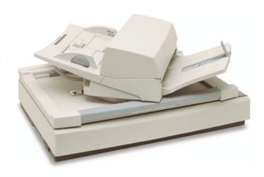
Table of Contents

Table of Contents
Table of Contents                                                               2

About the Scan Application                                                      4

Chapter 1: Scanner Set Up                                                       6

    About Scanner Configuration                                                 7

      About Scanner Configuration for Windows                                   8

        Using the Scan Configuration Editor                                     9

        Running the Findscanner Utility                                        13

        Configuring the Scanner Using the Configuration Wizard                 14

      About Scanner Configuration for GNU/Linux                                17

        Identifying the Name of the Scanner Device Driver                      18

        Setting the Permissions for the Scanner                                20

      About Configuring Scanners for Mac OS X                                  21

        Modifying the Scan.conf File                                           22

    Establishing Communication                                                 24

    About Adapting the Scanner Hardware                                        27

      Removing Paper Chute Cog Wheels                                          28

      Adding Paper Guides to Scanners                                          29

      Installing Tape on ADF Paper Paths                                       30

      Creating Off-set Scanning                                                34

    Calibrating Scanners with Peg Bars                                         35

Chapter 2: User Interface                                                      38

    Scan Module Top Menu                                                       41

Chapter 3: Pre-scanning Process                                                44

    Launching the Scan Application                                             45

    Creating Scenes in the Scan application                                    47

    Creating Elements from the Scan Module                                     50

    Loading Drawings                                                           52

    Editing Drawing Lists                                                      55

    Setting Up Scanning Sessions                                               57

                                                    2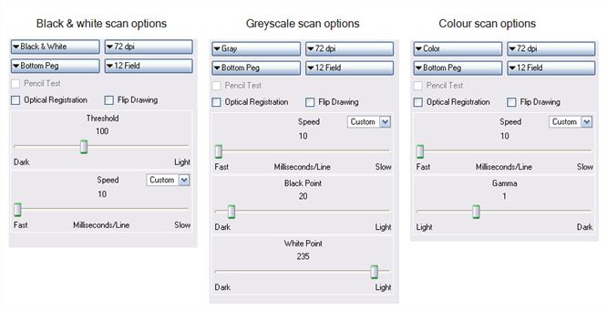
Harmony 21 Scan Documentation

      Displaying Scanner Information                  59

    Performing Trial Scans                            60

Chapter 4: Scanning                                   64

    Scanning with the Automatic Document Feeder       65

    Scanning Manually                                 68

    Scanning Pan Cels                                 70

    Stopping the Scanning Process                     72

Chapter 5: Advanced Scanning Techniques               74

    Scanning Drawings without Matching Frames         75

    Loading Previously Scanned Drawings               78

    Setting the Vectorization Style                   79

                                                  3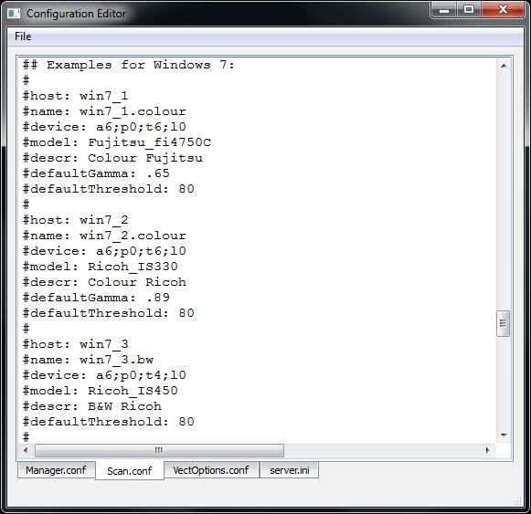
About the Scan Application

About the Scan Application

Toon Boom Harmony is a complete animation solution that offers a variety of tools to suit your needs, from pre-
production steps to the end of production. Some of these tools are provided in specialized modules, such as the
Paint, Scan and Play modules, which are designed to help you focus on a specific task to ensure the efficiency of
the entire production.

In this guide, you will learn how to use the Scan module and integrate it in your production workflow.

                                                        4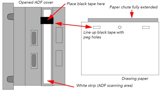
Harmony 21 Scan Documentation

                                5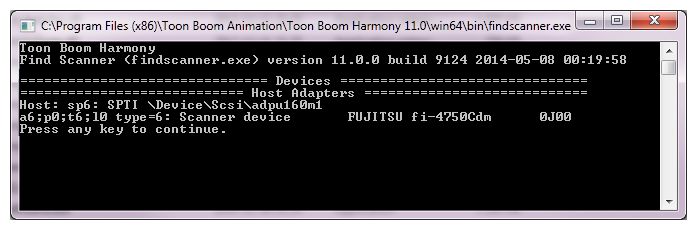
Chapter 1: Scanner Set Up

Chapter 1: Scanner Set Up
Before you can start scanning drawings, you will need to connect, configure, and calibrate your scanner to
work with Harmony. It is important that you install the scanner hardware according to the manufacturer's
instructions.

  About Scanner Configuration                                                                                 7

    About Scanner Configuration for Windows                                                                   8

       Using the Scan Configuration Editor                                                                    9

       Running the Findscanner Utility                                                                       13

       Configuring the Scanner Using the Configuration Wizard                                                14

    About Scanner Configuration for GNU/Linux                                                                17

       Identifying the Name of the Scanner Device Driver                                                     18

       Setting the Permissions for the Scanner                                                               20

    About Configuring Scanners for Mac OS X                                                                  21

       Modifying the Scan.conf File                                                                          22

  Establishing Communication                                                                                 24

  About Adapting the Scanner Hardware                                                                        27

    Removing Paper Chute Cog Wheels                                                                          28

    Adding Paper Guides to Scanners                                                                          29

    Installing Tape on ADF Paper Paths                                                                       30

    Creating Off-set Scanning                                                                                34

  Calibrating Scanners with Peg Bars                                                                         35

                                                       6
Harmony 21 Scan Documentation
About Scanner Configuration
Before you can start scanning drawings, you will need to configure your scanner to work with Harmony. The
instructions for this procedure are different depending on which platform you are using: Windows, macOS or
GNU/Linux.
About Scanner Configuration for Windows 8
Using the Scan Configuration Editor 9
Running the Findscanner Utility 13
Configuring the Scanner Using the Configuration Wizard 14
About Scanner Configuration for GNU/Linux 17
Identifying the Name of the Scanner Device Driver 18
Setting the Permissions for the Scanner 20
About Configuring Scanners for Mac OS X 21
Modifying the Scan.conf File 22
7Chapter 1: Scanner Set Up
About Scanner Configuration for Windows
After you have installed the hardware, you will need to configure your scanner. The findscanner utility will
help you obtain information about your scanner for the Configuration Wizard.
Using the Scan Configuration Editor 9
Running the Findscanner Utility 13
Configuring the Scanner Using the Configuration Wizard 14
8Harmony 21 Scan Documentation
Using the Scan Configuration Editor
Once you have recorded information about the scanner attached to your computer, you are ready to configure
your scanner to communicate with Harmony. Use the Harmony Configuration Editor to configure your scanner.
How to configure the scanner with the Configuration Editor
1. From the Start menu, select All Programs >Harmony 21 [edition] >Tools > Configuration Editor.
The Configuration Editor dialog box opens.
3. In the Configuration Editor dialog box, select the Scan.conf tab.
4. Scroll down the text until you reach the Examples for Windows 7 section.
9Chapter 1: Scanner Set Up
5. Using the list, locate the model of scanner connected to your computer.
l When you find the models that matches, edit the file to remove the pound signs (#) in front of each
lines of that example.
10Harmony 21 Scan Documentation
l If none of the models match the scanner connected to your computer, highlight all the lines of the
example that is the closest to your scanner model and paste them below that example. Once the
lines are pasted, edit the file by removing the pound signs (#) in front of each line of that new
example.
NOTE
Make sure that a pound sign (#) separates the pasted example from the one above and below
it.
6. Edit the following lines of the example:
host: Enter the hostname of the computer the scanner is connected to.
11Chapter 1: Scanner Set Up
NOTE
If you do not know the hostname of the computer, open a Command Prompt window, type the
"hostname" command and press Enter to obtain the name of the computer.
name: Enter a name for the scanner configuration that will appear in the Scan application.
device: Enter the information returned by the findscanner utility. Ex.: a6;p0;t5;l0
l If the example you just edited matches the scanner model connected to your
computer, read the information entered for the host, name and device, and decide if
you want to continue.
l If the configuration is accurate, then go to the File menu, save the changes made and
close the Configuration Editor.
l If the example you just edited did not match the scanner model connected to your
computer, you will need to edit the following lines as well:
model: Enter the model of the scanner connected to the computer.
NOTE
Make sure the scanner model is included in the supported scanner list found at the beginning
of the Scan.conf document and that the syntax is identical as well.
descr: Enter a short, but meaningful description of the scanner. Ex: B&W Ricoh or Colour Fujitsu.
7. If the information entered for the host, name, device, model and descr entry are accurate, then go to
the File menu, save the changes made to the file and close the Configuration Editor.
NOTE
Other configurations, like the default Threshold, Gamma, Black&White point and Resolution
can also be edited later if needed.
12Harmony 21 Scan Documentation
Running the Findscanner Utility
To configure your scanners using the Harmony Configuration Wizard, you need the following scanner
information:
l Adapter ID number
l Path ID
l Target ID
l Logical unit number (LUN)
To obtain this information, run the findscanner utility provided with Harmony. findscanner issues a report
including all this information.
How to run the Findscanner utility
1. Locate findscanner.exe. It is stored in \Program Files (x86)\Toon Boom
Animation\Harmony 21 [edition]\win64\bin.
2. Double-click on the file to start it.
A terminal or command prompt opens and displays a report. In this example, the scanner is on the
last line. The information you need is contained in this segment:
a6;p0;t6;l0.
‣ a6: The Adapter ID number. Its value is 6.
‣ p0: The Path ID. The value is 0.
‣ t6: The Target ID. The value is 6.
‣ l0: The logical unit number (LUN). The value is 0.
3. Record this information so you can enter it into the Harmony Configuration Wizard.
13Chapter 1: Scanner Set Up
Configuring the Scanner Using the Configuration Wizard
After upgrading your SCSI adapter and recording information about the scanner attached to your computer,
you are ready to configure the scanner to communicate with Harmony. Use the Harmony Configuration Wizard
to configure your scanner.
How to start the Harmony Configuration Wizard
1. From the Start menu, select All Programs > Harmony 21 [edition] > Tools > Configuration
Wizard.
The Harmony Configuration dialog box opens.
How to configure the scanner
1. In the Harmony Configuration dialog box, click Scanners Configuration.
The Scanner dialog box opens.
14Harmony 21 Scan Documentation
2. In the Name menu, type or select the scanner's name.
3. In the Model menu, select the scanner model.
4. In the Interface menu, select the scanner interface type.
5. From the SCSI controller number menu, select the SCSI number that identifies your SCSI Adapter.
6. From the SCSI ID menu, select the SCSI number of the scanner.
7. From the logical unit number (LUN) menu, select logical unit number. Due to a scanner's default
configuration and the nature of the device, the LUN should always be zero (0).
8. After you have completed all the fields in this dialog box, click Add.
9. Repeat the previous steps in this procedure for each scanner you want to add.
To remove a scanner from the list, select the scanner from the Name field and click Remove.
10. After you have added all your scanners, click Next.
The Review dialog box opens.
15Chapter 1: Scanner Set Up
11. Read the summary of how you have configured your scanner and decide if you want to continue.
l If the summary is accurate, click Finish to complete the configuration.
l If you want to change the configuration, click Back until you reach the dialog box where you can
change the option.
l After you make your changes, click Next until you reach the Review dialog box again.
A confirmation message appears when your Scanner configuration file (Scan.conf) is updated.
16Harmony 21 Scan Documentation
About Scanner Configuration for GNU/Linux
After you have installed the hardware, you will need to identify the name of the scanner device driver and set
permissions for the scanner.
Identifying the Name of the Scanner Device Driver 18
Setting the Permissions for the Scanner 20
17Chapter 1: Scanner Set Up
Identifying the Name of the Scanner Device Driver
You must identify the name of the SCSI device that is working with your scanner so that you can configure
Harmony to communicate with it.
Device drivers all have names starting with /dev/sg. If your scanner is the only generic SCSI device
connected to your system, it is likely that the name of its driver is
/dev/sga.
If you are uncertain about the device name, you can use the findscanner utility provided with Harmony. Use
the findscanner utility to probe your SCSI bus for devices. It will tell you the name of the device being used
by scanners attached to your system.
NOTE
The device name of your scanner will change if you add, remove or swap other generic SCSI
devices.
How to use the findscanner utility to identify the scanner
‣ Start the findscanner utility. While in the bin folder of your Harmony installation, type the
following in a terminal or command prompt:
./findscanner
The findscanner utility is installed in //usr/local/ToonBoomAnimation/harmony
[Edition]_21grep/ln86_64/bin/
If there are scanners connected to your computer and they are properly installed, the
findscanner utility will return information like the following:
/dev/sga type=6: Scanner device RICOH IS450 Vers:1R04
/dev/sgb type=6: Scanner device FUJITSU fi-4750Cdm Vers:0G00
If findscanner cannot find SCSI scanners attached to your computer, it will return a statement
like this:
No scsi devices attached
If you get this message, it may indicate that your system could not initialize your SCSI adapter at
boot time.
How to make sure the SCSI devices are initialized correctly when booting GNU/Linux
1. Go to the /boot directory and rename the initrd-[version].img file, where [version]
represents the version of your kernel. You can run the uname -r command to find out the version
18Harmony 21 Scan Documentation
of your kernel.
cd /boot
mv initrd-2.4.18-3.img noscsi-initrd-2.4.18-3.img
2. Type the following command:
/sbin/mkinitrd initrd-2.4.18-3.img 2.4.18-3
This command recreates a new "init ramdisk" image that will load your SCSI driver when your
system starts.
3. Reboot your system.
19Chapter 1: Scanner Set Up
Setting the Permissions for the Scanner
If you want multiple user accounts to be able to access your scanner, you must modify the permissions on the
device driver.
How to change the permissions on the scanner
1. On a command line, type the following:
chmod 666 /dev/sga
/dev/sga must represent the device driver of your scanner.
How to set the permissions on the scanner each time you boot
1. Open /etc/rc.d/rc.local in a text editor.
2. Add the following line:
chmod 666 /dev/sga
3. Save and close the file.
t and replace it with your own content.
20Harmony 21 Scan Documentation
About Configuring Scanners for Mac OS X
This chapter explains how to configure your scanner to work with Harmony on macOS.
Before you can configure your scanner, your scanner should already be configured, switched on, and connected
to your system.
After your scanner is configured, you must modify the hardware so Harmony can align images scanned using
autofeed.
Modifying the Scan.conf File 22
21Chapter 1: Scanner Set Up
Modifying the Scan.conf File
After you have installed your scanner hardware, you must configure your scanner to communicate with
Harmony. To do this, you must find the name of your scanner using the Find Scanner Utility. Then, you must
add this name to the Scan.conf file.
How to modify the Scan.conf file
1. Open a terminal and type the following:
findscanner.
IMPORTANT
The path to the Harmony's terminal applications must be registered for this process to work.
Refer to the macOS Installation chapter to learn how to register the path to the Terminal
application.
The findscanner utility reports the following information:
Device found:
The device found must be copied into the Scan.conf file, including the angle brackets.
2. Modify the Scan.conf file with the Harmony Configuration Editor. Open a Finder and select
Applications > Harmony 21 [edition] > Tools > Configuration Editor.
3. In the Harmony Configuration Editor, select the Scan.conf tab.
The following is an example of entries in a Scan.conf file for a Fujitsu scanner on macOS.
host: scan1
name: Fujitsu BW
model: Fujitsu_M4097D
device:
descr: The scanner to use for black & white and greyscale scans.
defaultGamma: .89
defaultResolution: 200
The following options must be included in the Scan.conf file:
• host: [hostName]
where [hostName] is the name of the machine that the scanner is attached to.
• name: [scannerName]
where [scannerName] is the name you want the scanner to be listed as in the scanner drop-list in
the Harmony.
• device:
22Harmony 21 Scan Documentation
where is the name the findscanner utility reports. You must include the angle
brackets.
• model:[modelName]
where [modelName] is the model name of your scanner (the name is case sensitive and there can be
no spaces separating the name and the number). Following is a list of supported scanners.
Epson_836XL
Epson_1640XL
Epson_GT-15000
Fujitsu_M3096G
Fujitsu_M4097D
Fujitsu_fi4750C
Fujitsu_fi5750C
Fujitsu_fi6770
Ricoh_IS330
Ricoh_IS420
Ricoh_IS430
Ricoh_IS450
Ricoh_IS760
TWAIN
23Chapter 1: Scanner Set Up
Establishing Communication
Once your scanner is set up and you know the device driver name, brand and model, you are ready to configure
the Scan.conf file so that the Harmony can communicate with it. The Scan.conf file contains a number of
configuration parameters you can use to control the communication between your scanner and the Harmony.
The Harmony Configuration Wizard updates the Scan.conf file with the required information. If there are
other variables you want to modify in this file, use the Harmony Configuration Editor.
Location of the Scan.conf File
Windows: C:\Program Files (x86)\Toon Boom Animation\Toon Boom Harmony 21
[Edition]\etc
macOS: /Applications/Toon Boom Harmony 21 [Edition]/Harmony
[Edition].app/Contents/tba/etc
GNU/Linux: /usr/local/ToonBoomAnimation/harmony[Edition]_21/etc
Location of Original Default Scan.conf File
Windows 7: C:\Program Files (x86)\Toon Boom Animation\Toon Boom Harmony 21
[Edition]\resources\samples
macOS: /Applications/Toon Boom Harmony 21 [Edition]/Harmony
[Edition].app/Contents/tba/resources/samples
GNU/Linux: /usr/local/ToonBoomAnimation/harmony[Edition]_21/resources/samples
Here is an example of entries in a Scan.conf file for a Ricoh scanner on Linux.
host: scan-1
name: My_Ricoh_IS450DE_Scanner
descr: The scanner to use for black & white and greyscale scans.
device: /dev/sga
model: Ricoh_IS450DE
defaultThreshold: 80
defaultResolution: 200
registrationStrictness: Loose
The following options must be included in the Scan.conf file:
l host: [hostName]
where [hostName] is the name of the machine the scanner is attached to.
l name: [scannerName]
where [scannerName] is the name you want the scanner to be listed as in the Scanner menu in the Scan
application.
l device:
l GNU/Linux: /dev/[filename]
24Harmony 21 Scan Documentation
where [filename] is the filename of the device driver for your scanner.
l Windows: scX;dY;lZ
The SCSI identifier for the scanner.
X=controller number (normally 0)
Y= device number (as set on the scanner)
Z= The logical unit (normally 0)
ex: device: sc0;d5;l0 (if the scanner is set to scsi id 5)
l macOS:
where is the name findscanner reports. You must include the angle
brackets.
l model:[modelName]
where [modelName] is model name of your scanner (the name is case sensitive and there can be no
spaces separating the name and the number). Following is a list of supported scanners.
Epson_1640XL
Epson_GT-15000
Fujitsu_M3096G
Fujitsu_M4097D
Fujitsu_fi4750C
Fujitsu_fi5750C
Fujitsu_fi6770
Ricoh_IS330
Ricoh_IS420
Ricoh_IS430
Ricoh_IS450
Ricoh_IS760
TWAIN
The following are optional additions to the scanner description.
l descr: [scannerDescription]
Where [scannerDescription] is a description of the scanner, which appears in the Scanner Information
dialog box in the Scan window. This text must be all on one line.
l defaultThreshold: [value]
Where [value] is the default value for threshold for black and white scanning. The value should be an
integer (0 £ [value] £ 255). The default threshold value at installation is 100 if no value is specified.
l defaultBlackPoint: [value]
25Chapter 1: Scanner Set Up
Where [value] is the colour value (0 < [value] < 255) that the Scan application considers to be black. The
Scan application forces any colour darker than this value to black. If no value is specified, it defaults to
20.
l defaultWhitePoint: [value]
Where [value] defines the colour value (0 < [value] < 255) that the Scan application considers white.
The Scan application forces any colour lighter than this value to white. If no value is specified, it defaults
to 235.
l defaultGamma: [value]
Where [value] is the default value for colour and grayscale gamma correction
(0.0 < [value] £ 2.55) on the scanner. The default gamma value at installation is 1.0 if no value is
specified.
l defaultResolution: [value]
Where [value] is the default resolution in dpi (dots per inch) for the scanner. The value should be an
integer that is one of the scanner's legal resolutions. The default resolution value at installation is 300.
For Fujitsu and Ricoh scanners, 300 DPI is appropriate. For colour scanners, like the Epson, 150 DPI is
suggested.
l defaultPegSide: [value]
Where [value] defines the default value in the Peg-Side menu when you select the scanner. You can
choose between Top, Right, Left or Bottom.
l registrationStrictness: [level]
Where [level] defines how exact the location of the peg holes must be for the software to recognize
them. You have two values to choose from:
l Strict: The peg holes must be in a tightly defined area to be recognized. This is the
default setting.
l Loose: The peg holes can be anywhere in a larger area to be recognized. This setting is
recommended.
l pegPitch: [value]
Where [value] is the number of decimal places permitted when defining the distance in inches between
side pegs. The peg pitch can be defined to fix splicing problems when aligning pan cels. The default
value is 8 (e.g., a distance of 0.12345678 could be defined).
side0CleanSize: [value]
side1CleanSize: [value]
side2CleanSize: [value]
side3CleanSize: [value]
Where [value] is the distance in inches from the edge of the drawing that will not be included in the
scan. Including these values can save vectorization time and remove dirtiness at the edges of a drawing.
Side "0" is the side with peg holes. Remaining sides are numbered in clockwise fashion.
26Harmony 21 Scan Documentation
About Adapting the Scanner Hardware
Before using your scanner, you must make a few minor adjustments to make sure it can handle the special
types of animation paper you will be using.
On the ADF paper chutes of supported Fujitsu scanners, the paper guides are connected to each other by a cog
wheel that keeps the paper guides and the drawings centred on the chute. Adjustments must be made to this
type of Fujitsu scanner to avoid problems during the scanning process.
To compensate for the centred scanning on the ADF chute of Fujitsu scanners, there are several things you can
do.
Removing Paper Chute Cog Wheels 28
Adding Paper Guides to Scanners 29
Installing Tape on ADF Paper Paths 30
Creating Off-set Scanning 34
27Chapter 1: Scanner Set Up
Removing Paper Chute Cog Wheels
If you don't want to modify the Scan.conf file, you can remove the cog wheel so the paper guides can slide
independently. This allows you to position the paper guide closest to the back of the scanner as far as it can go
towards the back of the scanner. You can then slide the other paper guide up to meet the bottom edge of the
stack of drawings to keep them aligned.
How to remove the cog wheel
1. Remove the paper chute from the scanner.
2. Remove the screw that attaches the cog wheel to the paper chute.
After you remove the cog, the paper guides should be able to slide independently of each other.
28Harmony 21 Scan Documentation
Adding Paper Guides to Scanners
Instead of removing the cog wheel on the ADF paper chute, you can make a paper guide to place between the
existing paper guides to keep the stack of drawings in the proper alignment in the paper chute.
To perform this procedure, you will need the following materials:
l A paper guide made of cardboard, a block of wood, or similar material.
l Adhesive tape to secure the paper guide to the paper chute.
How to place a paper guide on the scanner
1. Open the ADF paper guides to their widest position.
Place the paper guide closest to the back of the scanner as far out as it can go (toward the back of
the scanner).
If you did not remove the cog wheel, this will make for a very wide paper chute, wider than most of
your animation paper.
Now you must create an intermediate paper guide to hold your drawings in place.
2. Place a stack of drawings in the paper chute so that they are touching the back paper guide. Make
sure the back paper guide is as far back as it can go.
3. Position the paper guide you created to secure the other edge of the paper stack.
4. Secure the paper guide with tape.
29Chapter 1: Scanner Set Up
Installing Tape on ADF Paper Paths
When you scan drawings with the Scan application, drawings on paper become digital images in the Harmony
system. These digital images must be properly aligned during the scan process to ensure that the animation
flows smoothly from frame to frame in the final output.
• If you want to scan many drawings using the ADF chute on your scanner, you must use the Optical
Registration option in the Scan application to automatically align your drawings.
When you select the Optical Registration option, the Scan application identifies the peg holes to align
the drawings.
You can also use the Optical Registration option if you want to manually scan a drawing on the flatbed
part of the scanner.
• If you have a peg bar attached to your scanner, you don't have to use optical registration because the
drawings will be aligned by the peg bar. However, you will have to scan your drawings one at a time.
Peg holes in your drawings must be filled with black in the final scanned image for the optical registration to
be able to locate them. Your scanner must be modified prior to scanning to ensure black peg holes appear in
the scanned image.
For ADF Scanning
Tape a piece of dark paper to the ADF feeder in the position where the peg holes will pass as they are
scanned.
If you don't place the black tape on the ADF paper path, the peg holes in the drawing pass in front of a white
background. This does not provide enough contrast for the Scan application to distinguish where the peg
holes are and it will not be able to register and align the autofeed drawings.
For Manual Scanning
Tape a piece of dark paper to the scanner cover above the position of the peg holes.
30Harmony 21 Scan Documentation
RICOH Scanner
Fujitsu Scanner - ADF
31Chapter 1: Scanner Set Up
Fujitsu Scanner - Cover
Before you perform this procedure, you need the following materials:
l A strip of black adhesive tape approximately 1.25 inches (3.5 cm) by 0.75 inches (2 cm). Black plastic
electrician's tape is fine.
l A sheet of drawing paper with field size and peg hole locations identical to the type that you intend to
scan with the autofeeder.
How to install the tape on the ADF paper path
1. Turn off the scanner's power and open the ADF cover.
2. Place the paper guides in their scanning position. This will depend on your scanner and any
modifications you made to it.
3. Place the drawing paper in the paper chute with the peg holes toward the back of the scanner.
The top edge of the paper should touch the paper guide closest to the back of the scanner.
4. Slide the paper into ADF chute.
5. Place the strip of black tape across the width of the white strip on the inside of the ADF cover. Use
the peg holes in the drawing paper as a visual guide.
32Harmony 21 Scan Documentation
6. Close the ADF cover and scan a few test drawings to see that the Scan application can identify the
peg holes.
33Chapter 1: Scanner Set Up
Creating Off-set Scanning
Modifying the Scan.conf File for Centred ADF Scanning
If you do not want to modify the ADF chute so that it is aligned towards the back of the scanner, you can use
the leftOffset option in the Scan.conf file. To calculate the leftOffset option, consider that the paper
chute on all supported Fujitsu scanners are 12 inches (2.54 cm) wide . If your paper is 10.5 inches (26.67 cm)
wide, the difference between the chute and the paper is 1.5 inches (3.81 cm). Since this difference is
distributed on both sides of the paper chute, the offset from either edge is 0.75 inches (1.90 cm). Therefore, the
leftOffset option is 0.75 inches (1.90 cm).
The leftOffset option was added to this sample of the Scan.conf file:
host: scan-1
name: Fujitsu10.5
descr: The scanner to use for black & white and greyscale scans.
device: sc1;d5;l0
model: Fujitsu_fi4750C
defaultThreshold: 80
defaultResolution: 200
registrationStrictness: Loose
leftOffset: 0.75
You can add additional entries in the Scan.conf file to support paper of different sizes. For example:
host: scan-1
name: Fujitsu8
descr: The scanner to use for black & white and greyscale scans.
device: sc1;d5;l0
model: Fujitsu_fi4750C
defaultThreshold: 80
defaultResolution: 200
registrationStrictness: Loose
leftOffset: 2
34Harmony 21 Scan Documentation
Calibrating Scanners with Peg Bars
Autofed and manually pegged drawings must register against each other if you intend to use both scanning
methods. Therefore, you must calibrate the scanner so that it can register the peg holes accurately using the
peg bar.
Before you perform this procedure, you will need the following materials:
l An ultra-thin peg bar. Suggestion: Audio-Visual Stainless Steel Pegbar (catalog number AP105)
l Accurate ACME standard registration
l 3-peg, single-field length (0.05" x 1.5" x 12.0") (1.27mm x 38 mm x 304.7mm)
l Low brass pegs (1/16" in height) (1.58 mm in height)
l Lightweight sprung stainless steel base
l Ideal for work requiring exposure on a process camera, print down frame or scanning bed
This is obtainable from Chromacolour International www.chromacolour.com
l A drawing with field size and peg hole locations identical to the type you intend to scan.
Instead of using a drawing of a character or object, you may find it helpful to create a test "drawing" by
placing a sheet of drawing paper over a field chart and tracing several heavy line segments from the
field chart.
For more accurate calibration, draw lines from the centre to the edges of the paper. This will give more
reference points at various locations on the paper. For example, trace over the centre X and several
corners of the fields from the centre out towards the edges of the field chart. Then peg and autofeed the
test drawing as described in the following procedure.
Before calibrating the scanner:
l Create a small scene in Harmony using the test drawing.
l Using Control Center, create a job that has one scene.
l Using Harmony, create an exposure sheet for the job that has two drawing columns (one for the
drawing you will autofeed and one for the drawing you will manually peg before scanning).
35Chapter 1: Scanner Set Up
How to calibrate a scanner with a peg bar
1. Create a test scene.
2. Open the Scan application and open the elements you created.
3. Perform an Autofeed scan of the test drawing in the autofeed element, with Optical Registration
enabled.
4. After the drawing has vectorized, load it in Stage by reopening the scene.
5. Loosely tape the peg bar to the scanner bed (centre the bar horizontally on the scanner bed; move
the bar vertically on the top of the scanner bed).
6. Scan the pegged drawing with the Autofeed feature off.
7. After the drawings has vectorized, load it in Harmony by reopening the scene, and comparing its
alignment with the drawing scanned in step 4.
8. If the two images do not align, move the peg bar and rescan the pegged drawing again.
9. Repeat these steps until you have aligned the drawings. When the peg bar is in the desired
position, securely attach the peg bar to the scanner bed. Keep the test drawing for future use.
36Harmony 21 Scan Documentation
37Chapter 2: User Interface
Chapter 2: User Interface
It is important to become familiar with the following elements of the user interface as it will help you get
started using the Scan application. You can learn more about the highlights described here, and how to use
them in a production context throughout this guide.
When you start the Scan application for the first time, the default workspace is displayed. It contains all of the
main elements you need to use.
The Scan application has five major components.
Top Menu
The top menu contains most of the commands available in the Scan application.
38Harmony 21 Scan Documentation
The menu categories are:
Menu Description
File Lets you load drawings and manage exposure sheet elements.
Lets you modify the Drawing List, apply vectorization options and create a text
Edit
file of scan details for each scanned drawing.
Scanner Lets you eject a page from the scanner and display scanner information.
Lets you access the integrated help system and Scan application version
Help
information.
NOTE
In macOS, there is a Scan menu with the following commands: About Scan and Quit.
Control Panel
The Control panel allows you to set up the scan.
When you select a scan type, you can control the following:
l Exposure
l Contrast
l Time required to scan a line, measured in lines per millisecond.
39Chapter 2: User Interface
Drawing List
The Drawing list displays the names of the drawings loaded for scanning. As each drawing is scanned, this is
indicated.
Frame Preview Panel
The Frame Preview panel shows the upcoming frame to be scanned.
Image Panel
The Image panel displays the current drawing being scanned.
40Harmony 21 Scan Documentation
Scan Module Top Menu
The menu commands in the Scan application let you access commands for executing many different tasks.
Scan Menu
If you are using macOS, the Scan menu commands let you display product and version information, and close
the Harmony.
Command Description
About Scan Displays product and version information.
Exit In macOS, closes the Harmony and ends the current session.
File Menu
The File menu commands let you open drawings, select scanned drawings to load, create a list of labelled cells
and close your session.
Command Description
Opens the Database Selector dialog box in which you select the drawings to be
Open Drawings
scanned or add new scenes and elements to a job.
Load From File Lets you select a previously scanned drawing to load into the Scan module.
Build Manual List Opens the Manual List dialog box for you to create a list of labeled cells.
Exit In Windows or Linux, closes the Scan module and ends your current session.
41Chapter 2: User Interface
Edit Menu
The Edit menu commands let you open the drawing list, reverse the drawing list, select the vectorization style,
and create a plain text file for each scan.
Command Description
Drawing List Opens the Drawings Selector dialog box for labelling cells to accept drawings.
Reverse Drawing List Reverses the sequence of drawings in the Drawing List.
Opens the Vectorization Styles dialog box for selecting the vectorization style to
Vectorize Style
apply when scanning drawings.
Creates a plain text file for each subsequent scan. This file contains information
such as the paper size and DPI used during scanning. Each plain text file is
Create ScanInfo File
located in the same directory and has the same file name as the scanned image
with the file extension SI.
Scanner Menu
The Scanner menu commands let you eject paper from a scanner and access scanner information.
Command Description
Opens the Scanner Information dialog box to view scanner name, device, model,
Info
and description information.
Ejects a page from a scanner’s automatic document feeder (ADF). This command
Eject Page is only activated when a paper jam occurs. This option is not available on all the
scanners.
Help Menu
The Help menu commands let you access scanner information, identify problems when scanning and access
the documentation.
Command Description
About In Windows or Linux, displays product and version information.
42Harmony 21 Scan Documentation
Debug Mode Identifies a problem encountered in Harmony.
Help Opens the online help product documentation.
43Chapter 3: Pre-scanning Process
Chapter 3: Pre-scanning Process
Toon Boom Harmony's dedicated Scan application lets you scan drawings fast. It creates a drawing list from
the previously created exposure sheet. To use this module, you must create your exposure sheet in Harmony
before the scan process.
Usually, when you're ready for scanning, a scene has been created containing the elements to be scanned and
the exposure sheet has been filled.
If you have not previously prepared your scene’s exposure sheet or created your elements or scenes, you can
always create drawing lists, elements or scenes directly from the Scan application without having to go
through the Control Center.
Launching the Scan Application 45
Creating Scenes in the Scan application 47
Creating Elements from the Scan Module 50
Loading Drawings 52
Editing Drawing Lists 55
Setting Up Scanning Sessions 57
Displaying Scanner Information 59
Performing Trial Scans 60
44Harmony 21 Scan Documentation
Launching the Scan Application
You can launch the Scan application using the desktop icon of the application menu.
How to launch the Scan application
1. Depending on your operating system, do one of the following:
l Windows: Open the Start menu and, in the list of programs, select Harmony 21 [Edition] >
Scan.
l macOS: Do the following:
a. In Finder, proceed to Applications > Toon Boom Harmony 21 [Edition] and
double-click Harmony [Edition].
The main Harmony application launches.
b. In the top menu, select Harmony [Edition] > Tools > Scan.
l GNU/Linux: In the GNOME top menu, select Applications > Harmony 21 [Edition] >
Scan.
If no scanner is connected to your computer, or if a scanner is connected but its driver is not
installed, the following message will appear:
l Click Continue to open the Scan application. Note that you will not be able to scan.
l Click Exit Scan Program to quit the Scan application.
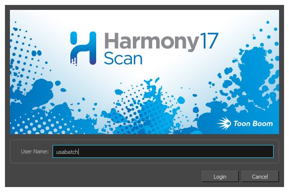
The database login dialog appears.
45Chapter 3: Pre-scanning Process
2. In the User Name field, enter your Harmony Server username.
3. Click Login.
46Harmony 21 Scan Documentation
Creating Scenes in the Scan application
Before you can scan drawings, you must have a scene, element and drawing list ready. You can create these
directly from the Scan application without having to go through the Control Center.
How to create a scene from the Scan application
1. Start the Scan application and log on to the database using your Harmony user name.
The Database Selector dialog box opens, displaying the Environments available from the Harmony
database.
2. Select the Environment and Job in which you want to add a scene.
3. Click Create Scene.
The Create Scene dialog box opens.
47Chapter 3: Pre-scanning Process
4. In the Scene Name(s) field, type the new scene’s name. Press Enter/Return after each scene’s name
to create additional scenes.
5. From the File System list, select the file system. Click the Other File System button to select
another file system to use.
To learn more about creating a project in the database, refer to the Control Center Guide.
6. Select where you want to place the new scenes in the database scene list using the Add Scenes
menu.
l At Bottom: Places new scenes at the bottom of the scenes list.
l At Top: Places new scenes at the top of the scenes list.
48Harmony 21 Scan Documentation
l Name Sort: Sorts new scenes alphabetically.
7. Click OK.
The new scenes appear in the Database Selector.
49Chapter 3: Pre-scanning Process
Creating Elements from the Scan Module
Elements don't need to be created in the Control Center, they can also be created in the Scan application.
How to create elements from the Scan application
1. Start the Scan application and log in to the database with your username.
The Database Selector dialog box opens, displaying the Environments available from the Harmony
database.
2. Select the Environment, Job and Scene in which you want to add elements.
3. Click Create Element.
NOTE
If your system administrator did not complete the resolution configuration tasks, a warning
message displays. This message notifies you that the resolution.conf file was not
properly inserted in the configuration folder.
4. Click OK.
50Harmony 21 Scan Documentation
The Scan application opens and the Create Element dialog box opens.
5. In the Name field, type the new element’s name.
6. Select Vector option if the element is to be vectorized.
7. Select the bitmap format of your element; this list is only available if you did not select the Vector
option.
8. Select a scan type.
l Colour: Creates a colour bitmap element.
l Greyscale: Creates a greyscale bitmap element.
l B&W: Creates a vector-based element that is going to be painted using the Harmony
or Paint modules.
9. Select the field chart size of your element.
10. When you're done:
l Click OK to add the element and return to the Database Selector.
l Click Add to add the element and keep the dialog box open to add more.
l Click Close to cancel and return to the Database Selector without adding an element.
51Chapter 3: Pre-scanning Process
Loading Drawings
There are two ways that you can load drawings from the Scan application.
How to load drawings from launch
1. Launch the Scan application and login.
2. The Database Selector dialog box opens, displaying the Environments available form the Harmony
database.
3. Select the Environment, Job, Scene and then the Element you want to scan.
4. Click Open.
The Drawings Selector dialog box opens, listing all the drawings contained in the selected
element.
52Harmony 21 Scan Documentation
The Drawing column displays the names of the drawings. The Scanned column indicates if the
drawing has been scanned.
5. If needed, add new drawings to the list by typing in a drawing name in the Add Drawing field and
click Add Drawing.
The new drawing appears in the list.
6. Select the drawings to scan.
‣ Select the specific drawings from the list. You can select several drawing using Shift + click.
l Click All to select all the drawings in the list.
l Click None to unselect all drawings.
l Click Scanned to select only the drawings that are indicated as scanned (Yes) in the
list.
l Click Unscanned to select only the drawings that are indicated as not scanned (No) in
the list.
7. Click OK.
The selected drawings appear in the Drawing List column.
53Chapter 3: Pre-scanning Process
Once your session is started, you can open the Database Selector window at any time to load other
drawings.
How to load drawings inside the Scan application
1. Select File > Open Drawings.
2. Follow steps 4 to 7 in the previous procedure: "How to start the Scan application and load your
scene".
54Harmony 21 Scan Documentation
Editing Drawing Lists
There are two ways you can edit a drawing list from the Scan application.
l Editing a drawing list when loading an element or
l Editing a drawing list when the element is already loaded.
How to edit a drawing list
1. In the Scan application, select Edit > Drawing List.
The Drawing Selector dialog box opens listing all the drawings contained in the loaded element.
l The Drawing column lists the name of the drawings.
l The Scanned column indicates if the drawing has been scanned.
2. In the Add Drawing field, type a drawing name.
3. Click Add Drawing.
The new drawing appears in the list.
4. Select the drawings you want to scan.
l Select specific drawings from the list. You can select several drawings using Shift +
click.
55Chapter 3: Pre-scanning Process
l Click All to select all the drawings in the list.
l Click None to unselect all drawings.
l Click Scanned to select only the drawings that are stated as scanned (Yes) in the list.
l Click Unscanned to select only the drawings that are stated as not scanned (No) in
the list.
5. Click OK.
The selected drawings appear in the Scan application Drawing List.
56Harmony 21 Scan Documentation
Setting Up Scanning Sessions
Once you have launched the Scan application and loaded your drawing list, you can set up your scan session
with the different scanner options in the Control panel.
How to set up the scan session
1. Start the Scan application and load your drawing list.
2. In the Control panel, select a scanner from the Scanner menu.
3. From the Scan Type menu, select a scan type. If there is more than one scanner connected to your
computer, only the scanners that support the selected scan type are displayed.
l Black & White: Scans a line art drawing that you will paint in the Paint or Harmony
modules.
l Greyscale: Captures the shades of grey in drawings.
l Colour: Scans a pre-coloured drawing, such as a background or overlay.
When you select a scan type, additional context-sensitive options appear on the lower part of the
Control panel.
4. From the Peg Position menu, set the location of the pegs or registration holes on the paper you are
scanning. The images will be automatically rotated based on your selection.
l Bottom Peg: The peg holes appear below the drawing.
l Top Peg: The peg holes appear above the drawing.
l Left Peg: The peg holes appear on the left of the drawing.
l Right Peg: The peg holes appear on the right of the drawing.
5. From the Resolution menu, select a resolution. This determines the quality and size of scanned
images. The resolutions that appear in the list depend on the selected scanner.
6. From the Field Size menu, select the size of the paper you are scanning. The different choices
appear in field units. Note that the autofeed mode does not support paper larger than 12 field.
7. Select the Pencil Test option if you want to perform a line test. A black and white image will be
created with no paintable colour art regions. If you select this option, the Scan: Pencil Test
57Chapter 3: Pre-scanning Process
Confirmation dialog box opens.
l Press Yes to confirm.
l Press No to cancel.
1. Select the Optical Registration option to automate the alignment of the drawings using the registration
holes on the drawing paper.
2. Select the Flip Drawing option to flip the scanned image horizontally and realign the registration holes.
Once you set up the main scanner options from the Control panel, you are ready for a test scan to
calibrate the scanned images.
58Harmony 21 Scan Documentation
Displaying Scanner Information
You can display the scanner information, such as the scanner name, device, model and description with the Info
command.
To display scanner information
1. From the top menu, select Scanner > Info.
The Scanner Information dialog box opens.
59Chapter 3: Pre-scanning Process
Performing Trial Scans
The Scan application allows you to perform test scans to determine the proper threshold or gamma setting for
a drawing. A test scan lets you preview the scanned image without saving it. You can perform a trial scan by
auto feeding the drawing through the scanner or by pegging the drawing on the scanner.
How to perform a trial scan
1. Start the Scan application and load your drawing list.
2. Place the drawing on the scanner pegs or in the automatic document feeder (ADF).
3. On the Control panel, select the appropriate feeding type from the Feed menu.
l Autofeed: Feeds the drawings through the ADF.
l Autofeed (One): Accepts one drawing from the ADF when the Scan button is pressed.
l Pegged: Scans a drawing from the flatbed each time the Scan button is pressed.
l Pegged (Many): Automatically scan a drawing from the flatbed every five to ten
seconds (depending on the time required to process the drawings).
l Pan Cel: Scans a drawing that is bigger than the scanner window in separate
sections.
4. Click Preview. If you are manually pegging the drawing, make sure to close the scanner cover
before you click the Preview button. When the scan is complete, the drawing appears in the Frame
Preview panel of the Harmony.
5. Adjust the image parameters. Different options appear on the Control panel depending on the scan
type you selected—see Setting Up Scanning Sessions on page 57.
60Harmony 21 Scan Documentation
Scan Type Parameter
Speed: Adjusts the time required to scan a line (measured in lines per
millisecond) at which to scan drawings, if your scanner supports variable
All
speeds. Use the drop-down menu to set predefined speeds of Fast, Normal,
or Custom.
Black & White Threshold: Adjusts the exposure.
Black Point: Use this slider with the White Point slider to adjust the
contrast. Greyscale values that are less than the selected value are
converted to black.
Greyscale
White Point: Use this slider with the Black Point slider to adjust the
contrast. Greyscale values that are greater than the selected value are
converted to white.
Colour Gamma: Adjusts the colour contrast.
Scan Type Parameter
Speed: Adjusts the time required to scan a line (measured in lines per
millisecond) at which to scan drawings, if your scanner supports variable
All
speeds. Use the drop-down menu to set predefined speeds of Fast, Normal,
or Custom.
Black & White Threshold: Adjusts the exposure.
Greyscale Black Point: Use this slider with the White Point slider to adjust the
61Chapter 3: Pre-scanning Process
contrast. Greyscale values that are less than the selected value are
converted to black.
White Point: Use this slider with the Black Point slider to adjust the
contrast. Greyscale values that are greater than the selected value are
converted to white.
Colour Gamma: Adjusts the colour contrast.
6. Click Preview to view the changes.
7. Keep adjusting these values until you get the effect you want. These values will be applied to all
the subsequent drawings you scan.
NOTE
To keep the image from a trial scan without having to rescan the drawing, click Save to assign the
image to the currently selected drawing name in the Drawing list and mark it as scanned.
62Harmony 21 Scan Documentation
63Chapter 4: Scanning
Chapter 4: Scanning
After building your exposure sheet, opening the cells in the Harmony, configuring the scanner, fine tuning the
scan settings and previewing the scanned drawings, you are now ready to begin the final scanning process.
There are five ways to feed drawings through the scanner:
l Autofeed: Scans all drawings in the automatic document feeder (ADF).
l Autofeed (One): Scans the drawings in the ADF one at a time, and click Scan for each drawing.
l Pegged: Scans a drawing on the scanner. Click Scan each time you change the drawing on the scanner.
l Pegged (Many): Automatically scans the drawing in the scanner every five to ten seconds (depending
on the time required to process the drawings).
However, this mode does not scan each drawing automatically when you click the Preview button.
l Pan Cel: Scans a drawing into the system in separate sections because the drawing is bigger than the
scan window.
You may find that the Autofeed option is not available on your system, since your scanner may not support it.
The field size you select can also determine which mode is available.
l All scanning modes support 12 field.
l The Autofeed modes do not support 16 field or higher.
Drawings are scanned in the order in which they appear in the Drawing list.
NOTE
l If you want to reverse the order of the drawings, select Edit > Reverse List Order.
l If you want to make any other sorting changes, reselect the drawings from the Drawing
Selector dialog box.
l You may need to re-enter your list of drawings using the File > Build Manual List command.
Scanning with the Automatic Document Feeder 65
Scanning Manually 68
Scanning Pan Cels 70
Stopping the Scanning Process 72
64Harmony 21 Scan Documentation
Scanning with the Automatic Document Feeder
If the selected scanner supports an automatic document feeder (ADF), you can set your scanner to
automatically feed the drawings for scanning. There are two options for doing this: automatically scanning the
drawings or scanning drawings one at a time.
You can use the ADF to scan a stack of drawings continuously on a black and white scanner. Many scanner
models support up to A3-sized paper in the ADF (15 field). If you are scanning a 16-field drawing, you may
have to manually peg it on the scanner.
Since you must splice multiple drawings in a pan cel together once you have scanned them all, you cannot feed
pan drawings through the ADF. When you use the black and white scanner’s ADF to scan a stack of drawings,
the scanner optically detects the peg holes on the drawing and registers the image accordingly.
How to scan your drawing using the automatic document feeder (ADF)
1. Start the Harmony and load your drawing list.
2. In the Control panel, select a feed type from the Feed menu:
l Autofeed: Scans all the drawings in the automatic document feed (ADF).
l Autofeed (One): Accepts one drawing from the ADF when the Scan button is pressed.
3. Sort the paper drawings in your scanner in the same order as they appear in the Drawing List.
The Scan application uses the Drawing list order to scan the drawings.
4. If need be, reorder the Drawing list:
l To reselect the drawings you want to scan, select Edit > Drawing List.
l To reverse the Drawing list order, select Reverse List Order
65Chapter 4: Scanning
5. Before placing the drawings in the ADF paper chute, position the paper guide closest to the back of
the scanner as far out as it can go (towards the back of the scanner).
6. Place the drawings in the ADF paper chute (either face up or face down, depending on the type of
scanner you have).
l The first drawing to scan must be at the bottom of the stack once you put it on the
scanner, with the registration holes towards the back of the scanner (where the pegs
are).
l When you place the drawings in the ADF paper chute, insert them so that they are
slightly touching the paper guide closest to the back of the scanner, and the edge of
the drawings lightly touch the inside of the ADF.
NOTE
Do not insert the drawings too tightly on the inside of the ADF or multiple drawings may feed
through at the same time, causing registration errors.
1. Slide the other paper guide over (closest to the front of the scanner) so that it slightly touches the
drawings. You are now ready to scan the drawings.
2. Select a scanning mode from the Feed menu:
l Autofeed: Scans all the drawings in the automatic document feed (ADF).
l Autofeed (One): Accepts one drawing from the ADF when the Scan button is pressed.
3. Click Scan.
The scanner begins to capture the drawings. You can interrupt the scan by clicking the Stop button—
see Stopping the Scanning Process on page 72.
As the scanner captures the drawings:
l The drawing appears in the Image panel.
l You should check the drawings as the scanner captures them to ensure that the line
quality is consistent from drawing to drawing. If necessary, adjust the threshold for a
drawing.
l You can modify the scale to better view the drawings.
l If you selected the Autofeed option, the animator’s label for the drawing you just scanned
appears in the Last Scanned panel, which appears only when using the Autofeed or
Autofeed (One) modes. A portion of the entire scanned image appears in this window.
Scroll to the animator’s label using the scroll bars.
l The entire drawing appears in Frame Preview panel.
66Harmony 21 Scan Documentation
l When the scan is complete, the Drawing List tags the drawing as Scanned and highlights
the next drawing.
l If an optical registration error occurs, a dialog box appears.
- Make sure to place the drawing correctly in the ADF and there are no tears or rips on the
drawing’s registration holes. Try feeding and scanning the drawing again by clicking Retry.
- The size of the paper you used may not be close enough to a standard 12-field paper size.
Harmony looks for the centre peg hole at a specific distance from the leading edge of the paper (give
or take an inch).
- To correct this error, you must scan these drawings on a flatbed scanner instead of using an ADF
scanner.
- To continue scanning and fix the drawing later, click Skip Drawing. The scanner marks the
drawing as "Not Scanned" and the autofeed takes the next drawing.
When the scanner captures the last drawing in the Drawing List, the Scan and Preview buttons
become active again.
4. If you want to rescan a drawing, simply select the cell name from the Drawing List and click Scan.
l Remember to change the feed mode you selected before clicking the Scan button. If you
are scanning one drawing, select Autofeed (One) from the Feed menu.
l If you are rescanning more than one drawing, select Edit > Drawing List, type the names
of the drawings you want to rescan, and click OK.
NOTE
If a paper jam occurs in the ADF (with the compatible scanners), use the Eject Page command to
eject the jammed page. Select Scanner > Eject Page. If the option is not compatible with your
scanner, the command will be greyed out.
67You can also read