S8000 -100 Chilled Mirror Hygrometer User Manual - 97606 Issue 1 June 2021 - Process ...
←
→
Page content transcription
If your browser does not render page correctly, please read the page content below
S8000 -100
Chilled Mirror Hygrometer
       User Manual

         97606 Issue 1
           June 2021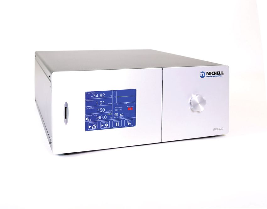
Please fill out the form(s) below for each instrument that has been purchased.

 Use this information when contacting Michell Instruments for service purposes.

Product Name

Order Code

Serial Number

Invoice Date

Installation Location

Tag Number

Product Name

Order Code

Serial Number

Invoice Date

Installation Location

Tag Number

Product Name

Order Code

Serial Number

Invoice Date

Installation Location

Tag Number
S8000 -100

          For Michell Instruments' contact information please go to
                             www.michell.com

                             © 2021 Michell Instruments
  This document is the property of Michell Instruments Ltd and may not be copied or
otherwise reproduced, communicated in any way to third parties, nor stored in any Data
Processing System without the express written authorization of Michell Instruments Ltd.
S8000 -100 User Manual

Contents
Safety................................................................................................................................vii
     Electrical Safety...........................................................................................................vii
     Pressure Safety............................................................................................................vii
     Toxic Materials.............................................................................................................vii
     Repair and Maintenance...............................................................................................vii
     Calibration...................................................................................................................vii
     Safety Conformity........................................................................................................vii
Abbreviations..................................................................................................................... viii
Warnings........................................................................................................................... viii

1      INTRODUCTION.................................................................................................1
       1.1      Operating Principle.............................................................................................. 1

2      INSTALLATION...................................................................................................3
       2.1    Safety................................................................................................................. 3
       2.2    Unpacking the Instrument.................................................................................... 3
       2.3    Transit Bolts........................................................................................................ 4
       2.4    Operating Requirements...................................................................................... 5
       2.4.1     Environmental Requirements.......................................................................... 5
       2.4.2     Electrical Requirements.................................................................................. 5
       2.4.2.1         Front Panel.............................................................................................. 6
       2.4.2.2         Rear Panel Connections............................................................................ 7
       2.4.3     Power Supply Input........................................................................................ 8
       2.4.4     Microscope installation................................................................................... 9
       2.4.5     Analog Output Connections........................................................................... 10
       2.4.6     Alarm Output Connections............................................................................ 11
       2.4.7     Remote Temperature Probe ......................................................................... 11
       2.4.8     Remote Pt100 connections............................................................................ 12
       2.4.9     USB Communications Port Connector............................................................. 12
       2.4.10    Ethernet/RS232/RS485 Port (optional)........................................................... 13

3      OPERATION.....................................................................................................14
       3.1    General Operational Information......................................................................... 14
       3.1.1     Sample Flow Adjustment.............................................................................. 14
       3.2    Operational Functions........................................................................................ 15
       3.2.1     Operating Cycle........................................................................................... 15
       3.3    Operating Guide................................................................................................ 16
       3.3.1     Automatic Mode........................................................................................... 16
       3.3.1.1       Description............................................................................................ 16
       3.3.1.2       Operating Practice.................................................................................. 17
       3.3.1.3       Flood Recovery...................................................................................... 17
       3.4    Manual Mode.................................................................................................... 18
       3.4.1     Description.................................................................................................. 18
       3.4.1.1       Operating Practice.................................................................................. 18
       3.4.2     Shutdown Procedure.................................................................................... 19
       3.4.3     DCC – Dynamic Contamination Control.......................................................... 20
       3.4.4     MAXCOOL Function...................................................................................... 20
       3.4.5     Pressure Input............................................................................................. 21
       3.4.6     Data Logging............................................................................................... 21
       3.4.7     Frost Assurance Technology (FAST)............................................................... 21
       3.4.8     STANDBY Mode........................................................................................... 21

iv
   97606 Issue 1, June 2021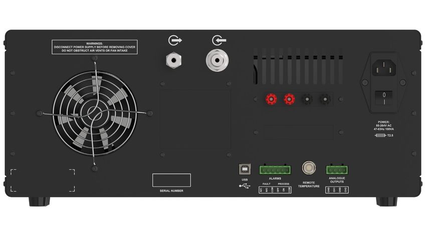
S8000 -100 User Manual

    3.5    User Interface................................................................................................... 22
    3.5.1     Main Screen................................................................................................. 22
    3.5.2     Customizable Readouts................................................................................ 23
    3.5.2.1        Full-Screen Mode................................................................................... 23
    3.5.3     Operational Status Display............................................................................ 24
    3.5.4     Cooler Setup................................................................................................ 25
    3.5.5     Setup Menu Screen...................................................................................... 26
    3.5.5.1        Numeric Input....................................................................................... 27
    3.5.5.2        Leaving Menus....................................................................................... 27
    3.5.6     Menu Structure ........................................................................................... 28
    3.5.7     DCC............................................................................................................ 29
    3.5.8     LOGGING.................................................................................................... 30
    3.5.9     OUTPUTS.................................................................................................... 31
    3.5.10    ALARM........................................................................................................ 32
    3.5.11    DISPLAY . ................................................................................................... 33
    3.5.12    CLOCK........................................................................................................ 34
    3.5.13    Inputs......................................................................................................... 34
    3.5.14    Comms....................................................................................................... 35
    3.5.15    Network Settings......................................................................................... 35
    3.5.16    Extended Settings........................................................................................ 36

4   WARNINGS AND FAULTS...................................................................................37
    4.1      Fault Codes....................................................................................................... 38
    4.2      Optics Warning.................................................................................................. 38

5   MAINTENANCE.................................................................................................39
    5.1      Sensor Mirror Cleaning....................................................................................... 39
    5.2      Fuse Replacement............................................................................................. 41

6   APPLICATION SOFTWARE.................................................................................42

Tables
Table   1            Front Panel Controls.....................................................................................6
Table   2            Rear Panel Connections................................................................................7
Table   3            Main Screen Description.............................................................................. 23
Table   4            Operational Status Display ......................................................................... 24
Table   5            Cooler Setup Parameters............................................................................. 25
Table   6            Cooler Alarm Warnings............................................................................... 25
Table   7            DCC Parameters......................................................................................... 29
Table   8            Logging Parameters.................................................................................... 30
Table   9            Outputs Parameters.................................................................................... 31
Table   10           Alarm Parameters....................................................................................... 32
Table   11           Display Parameters..................................................................................... 33
Table   12           Clock Parameters........................................................................................ 34
Table   13           Inputs Parameters...................................................................................... 34
Table   14           Comms Parameters.................................................................................... 35
Table   15           Network Parameters................................................................................... 35
Table   16           Extended Settings Parameters..................................................................... 36

Michell Instruments		                                                                                                                v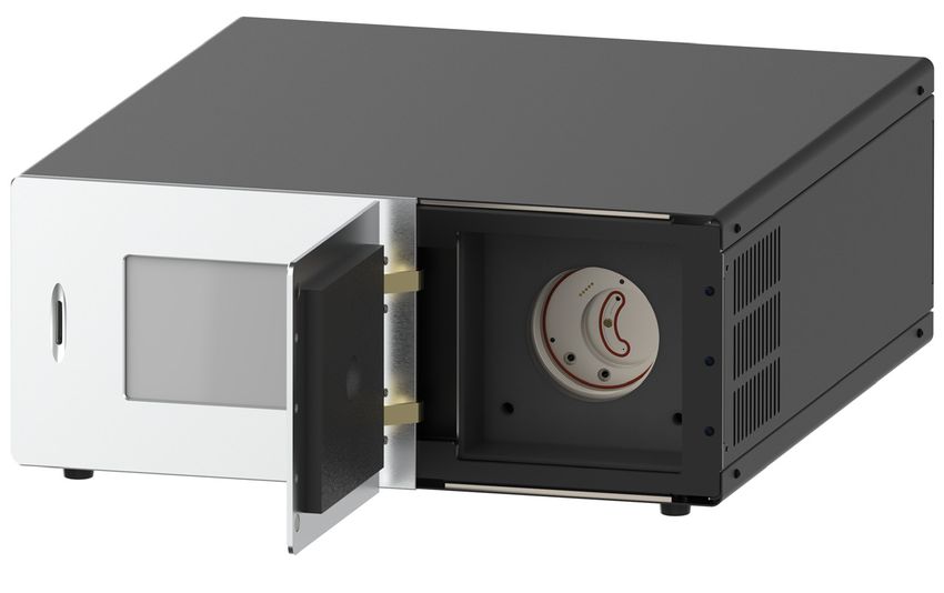
S8000 -100 User Manual

Figures
Figure   1    Operating Principle......................................................................................2
Figure   2    Transit Bolt Locations...................................................................................4
Figure   3    Front Panel.................................................................................................6
Figure   4    Rear Panel..................................................................................................7
Figure   5    Microscope Installation Procedure.................................................................9
Figure   6    Alarm and Analog Output Connection..........................................................10
Figure   7    USB Port Connection..................................................................................12
Figure   8    Ethernet Port............................................................................................13
Figure   9    RS232/485 Port (optional)..........................................................................13
Figure   10   Typical Operating Cycle..............................................................................15
Figure   11   Main Screen..............................................................................................22
Figure   12   Cooler Setup Screen..................................................................................25
Figure   13   Setup Menu Screen...................................................................................26
Figure   14   Virtual Keyboard . .....................................................................................27
Figure   15   Menu Structure.........................................................................................28
Figure   16   DCC Screen...............................................................................................29
Figure   17   Logging Screen.........................................................................................30
Figure   18   Outputs Screen.........................................................................................31
Figure   19   Alarm Screen............................................................................................32
Figure   20   Display Screen..........................................................................................33
Figure   21   Clock Screen.............................................................................................34
Figure   22   Inputs Screen...........................................................................................34
Figure   23   Comms Screen..........................................................................................35
Figure   24   Network Settings Screen............................................................................35
Figure   25   Extended Settings Screen...........................................................................36
Figure   26   System Alarm Screen.................................................................................37
Figure   27   Power Supply Fuse Replacement................................................................41

Appendices
Appendix A    Technical Specifications............................................................................... 43
              A.1       Dimensions.................................................................................. 44
Appendix B    Modbus Register Map................................................................................. 46
Appendix C    Quality, Recycling & Warranty Information.................................................... 55
Appendix D    Return Document & Decontamination Declaration......................................... 57

vi
   97606 Issue 1, June 2021
S8000 -100 User Manual

Safety
The manufacturer has designed this equipment to be safe when operated using the procedures
detailed in this manual. The user must not use this equipment for any other purpose than that
stated. Do not apply values greater than the maximum value stated.

This manual contains operating and safety instructions, which must be followed to ensure the safe
operation and to maintain the equipment in a safe condition. The safety instructions are either
warnings or cautions issued to protect the user and the equipment from injury or damage. Use
competent personnel using good engineering practice for all procedures in this manual.

Electrical Safety
The instrument is designed to be completely safe when used with options and accessories supplied
by the manufacturer for use with the instrument.

Pressure Safety

DO NOT permit pressures greater than the safe working pressure to be applied to the instrument. The
specified safe working pressure is 0.06 MPa (0.6 barg / 8.7 psig). Refer to the Technical Specifications
in Appendix A.

Toxic Materials

The use of hazardous materials in the construction of this instrument has been minimized. During
normal operation it is not possible for the user to come into contact with any hazardous substance
which might be employed in the construction of the instrument. Care should, however, be exercised
during maintenance and the disposal of certain parts.

Repair and Maintenance

The instrument must be maintained either by the manufacturer or an accredited service agent. For
Michell Instruments’ contact information please go to www.michell.com.

Calibration

The recommended calibration interval for this instrument is 12 months. The instrument should be
returned to the manufacturer, Michell Instruments Ltd, or one of their accredited service agents, for
re-calibration.

Safety Conformity

This product meets the essential protection requirements of the relevant EU and US standards
and directives. Further details of applied standards may be found in the Technical Specifications in
Appendix A.

Michell Instruments		                                                                                vii
S8000 -100 User Manual

Abbreviations

      The following abbreviations are used in this manual:
      barg            bar gauge (100 kPa or 0.987 atm)
      ºC              degrees Celsius
      ºF              degrees Fahrenheit
      DC              direct current
      g               grams
      in              inch(es)
      µm              micrometer
      m/sec           meters per second
      mA              milliampere
      mm              millimetres
      MPa             megapascal
      Nl/min          normal liters per minute
      Nm              Newton meter
      oz              ounces
      psig            pounds per square inch
      RH              relative humidity
      scfh            standard cubic feet per hour
      fps             feet per second
      T               temperature
      V               Volts
      Ω               Ohms
      ø               diameter

Warnings

      The general warnings listed below are applicable to this instrument. They are repeated
      in the text in the appropriate locations.

            !
                         Where this hazard warning symbol appears in the following
                       sections, it is used to indicate areas where potentially hazardous
                                        operations need to be carried out.

                       Where this symbol appears in the following sections it is used to
          DANGER
          Electric
                              indicate areas of potential risk of electric shock.
         Shock Risk

viii
     97606 Issue 1, June 2021
S8000 -100 User Manual                                                  INTRODUCTION

1     INTRODUCTION

      The S8000 -100 is a high-precision laboratory reference instrument for the measurement
      of moisture content in air and other gases. Relative humidity and other calculated
      parameters based on dew point, pressure and temperature of the sample gas can also
      be displayed. Gases can be sampled at a maximum pressure of 0.06 MPa (0.6 barg /
      8.7 psig).

      The S8000 -100 is capable of measuring dew points as low as -100 °C (-148 °F), and
      up to a maximum of +20 °C (+68 °F).

1.1   Operating Principle

      The system operates on the chilled mirror principle, whereby a gas sample is passed
      into the sensor housing and flows over the surface of the chilled mirror contained
      within. At a temperature dependent upon the moisture content in the gas, and the
      operating pressure, the moisture in the gas condenses out on the surface of the mirror.

      An optical system is used to detect the point at which this occurs, and this information
      is used to control the mirror temperature and maintain a constant thickness of the
      condensation layer on the mirror surface.

      A light-emitting diode (1) provides a light beam of constant intensity which is focused
      by a lens system (2) to become the incident beam on the mirror surface (3), flooding it
      with a pool of light.

      Before the light beam reaches the mirror (3), a beam splitter (4) directs part of the
      beam via a lens system (5) onto a sensor (6), which monitors the intensity of the LED
      light and provides a feedback loop to keep this at a constant level.

      Two sensors (7 and 8) monitor the light level reflected by the mirror. One of these
      sensors (7) measures the light level due to the reflected incident beam, and the other
      (8) measures the degree of light scatter due to the formation of water/ice on the mirror
      surface. Each sensor has its own optical lens system (9 and 10) to concentrate the
      reflected light onto the sensor.

      The output from each of these sensors is compared and then used to control the drive to
      a Thermo-electric cooler (11). Dependant on the result of this comparison, the control
      system will cause the heat pump (11) to either heat or cool the mirror (3) in order to
      maintain the desired condensation film thickness on the mirror surface.

      At an equilibrium point, where the evaporation rate and condensation rate on the surface
      of the mirror are equal, the mirror temperature, read by a Pt100 platinum resistance
      thermometer (12) embedded in the mirror, represents the dew point.

Michell Instruments		                                                                       1
INTRODUCTION                                                 S8000 -100 User Manual

    The ‘hot’ side of the Thermo-electric cooler is coupled to an auxiliary cooling system
    through a thermal mass (13), which smooths its response. The cooling system removes
    heat from the hot side of the Thermo-electric cooler, by cooling it to an appropriate
    temperature. This supplements the depression capabilities and enables measurement
    of very low dew points.

                                             4         9          7

                 1

            5
     6

                              2
                                                                                       8

                              3
                                                                                 10

                                                                       12
                     11

                                                                            13

                                  Figure 1       Operating Principle

2
  97606 Issue 1, June 2021
S8000 -100 User Manual INSTALLATION
2 INSTALLATION
2.1 Safety
It is essential that the installation of the electrical and gas
! supplies to this instrument be undertaken by competent
personnel.
2.2 Unpacking the Instrument
The S8000 -100 is a heavy instrument and should be unpacked by two people. Carefully
open the crate and check for any signs of transit damage before touching the instrument.
Remove the accessories before removing the instrument.
Carefully lift the unit out, holding the case and not the foam.
Ensure one person has a good grip of the unit whilst the other removes the foam
protectors.
Save all the packing materials for the purpose of returning the instrument for
re-calibration or any warranty claims.
Failure to return the instrument in the original packing, or failure to return the instrument
with the transit bolts engaged, may result in warranty claims being denied.
The accessories crate should contain the following items:
• UKAS Accredited calibration certificate
• Pressure transmitter calibration certificate
• SD card
• USB or Ethernet communications cable
• IEC power cable
• Microscope + lens cover
• Remote Pt100 temperature probe (optional)
• Optics cleaning kit (optional)
If there are any shortages, please notify the supplier immediately.
Michell Instruments 3INSTALLATION S8000 -100 User Manual
2.3 Transit Bolts
WARNING: The sensor assembly is equipped with transit
! bolts to prevent vibration damage during shipping. These
must be released prior to operation.
To release:
1. Open enclosure door.
2. Insert 5mm Allen key through each access hole in the insulation in turn
(see Figure 2).
3. Rotate clockwise until lock bolts reach their end stops.
Figure 2 Transit Bolt Locations
If the instrument needs to be shipped, then the transit bolts should be engaged before
placing into the original packaging.
To engage:
1. Open the enclosure door.
2. Insert 5mm Allen key through each access hole in the insulation in turn
(see Figure 2).
3. Rotate anti-clockwise until lock bolts reach their end stops.
4
97606 Issue 1, June 2021S8000 -100 User Manual INSTALLATION
2.4 Operating Requirements
2.4.1 Environmental Requirements
It is important to operate the S8000 -100 within the following environmental conditions:
Minimum Operating Temperature 5°C
Maximum Operating Temperature 30°C
Maximum Relative Humidity 80%
2.4.2 Electrical Requirements
The S8000 -100 requires the following electrical supply:
• 85...264 V AC, 47/63 Hz, 185 VA max.
• Alarm outputs comprise two sets of changeover relay contacts, one set
for a PROCESS alarm and one set for an INSTRUMENT FAULT. Both sets
of contacts are rated at 30 V, 1A. NOTE: THIS RATING MUST NOT BE
EXCEEDED.
Michell Instruments 5INSTALLATION S8000 -100 User Manual
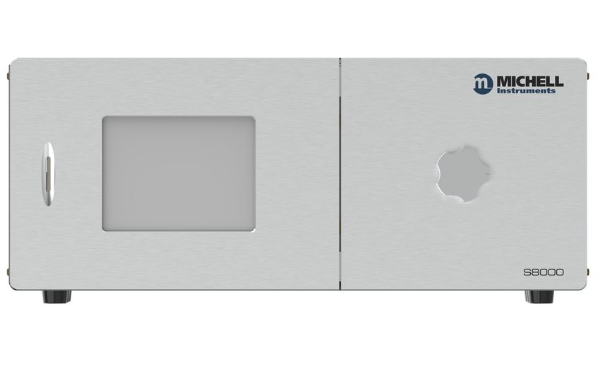
2.4.2.1 Front Panel
1 2 3 4
Figure 3 Front Panel
No Name Description
Takes an SD card used to store logged data
1 SD Card Slot See Section 3.5.8 for more details on how to use the logging
features
Displays measured values and enables the user to control the
Touch Screen operation of the instrument
2
Display See Section 3.5 for information about the touch screen and
menu system
Door covering the sensor chamber
3 Sensor Housing See Section 5.1 for instructions on how to open the sensor and
clean the mirror
Cap covering the microscope port when not in use. Also used
Microscope port
4 as the key to open the sensor window. See Section 5.1 for
cap
further details.
Table 1 Front Panel Controls
6
97606 Issue 1, June 2021S8000 -100 User Manual INSTALLATION
2.4.2.2 Rear Panel Connections
1 2 3 4
9
5 6 7 8
Figure 4 Rear Panel
No. Name Description
¼” Swagelok Connection for venting sample gas to atmosphere or vent line
1 once it has passed through the instrument
Gas Outlet
Connection for supplying the instrument with sample gas, usually
¼” VCR Gas
2 at a pressure slightly higher than atmospheric to maintain flow
Inlet through the instrument
Banana sockets for external 4-wire measurement of the internal
External PRT
3 PRT
Connection
See Section 2.4.8 for more information.
Universal power input 85...264 V AC, 47/63 Hz
Mains power
4 Fuse - 3.15 A, Anti-Surge, Glass, 20mm x 5mm
IEC Socket
Features integrated power ON/OFF switch
USB Type B Used for communication with the instrument via the application
5 software
socket
Process and Fault alarm outputs
6-Way Alarm See Section 2.4.6 for general information on the alarm relays
6
Relay Connector See Section 3.5.10 for instructions on how to configure the process
alarm
Remote
6-Pin Lemo socket for connection of remote Pt100 temperature
7 Temperature
probe
Probe Connector
Two configurable 2-wire channels providing 0...20 mA or 4...20 mA
4-Way Analog output. The outputs are active (sourcing) and must be connected
8 Output to a passive (sinking) input on the receiving equipment.
Connector See Section 3.5.9 for instructions on how to configure the analog
outputs
Either a DB9 socket (RS232 or RS485 comms option), or RJ45
Additional
(ethernet comms option). Used for digital communication.
9 Comms Socket
See Section 2.4.10 for details on how to configure the network
(Optional) settings
Table 2 Rear Panel Connections
Michell Instruments 7INSTALLATION S8000 -100 User Manual
These tasks should only be undertaken by competent
! personnel.
All the connections to the rear panel are electrical
connections.
DANGER
Exercise due caution, particularly when connecting to
Electric external alarm circuits which could be at high potential.
Shock Risk
Connections to the rear panel of the instrument are explained in the following sections.
2.4.3 Power Supply Input
The AC power supply is a push fit into the IEC C13 power input socket.
! Ensure the power switch is OFF before connecting the cable.
The voltage range is 85...264 V AC, 47/63 Hz.
8
97606 Issue 1, June 2021S8000 -100 User Manual INSTALLATION
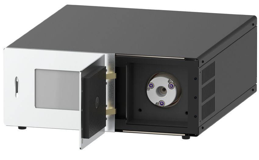
2.4.4 Microscope installation
To prevent any disturbance to the frost formation on the mirror, when required the
microscope should be installed prior to starting a measurement. The microscope lens
cover should be placed over the eyepiece when the mirror is not being observed.
1. Remove the gas block key from the enclosure door by rotating it until the
retaining lugs align with the slots in the panel.
2. Open the enclosure door.
3. Remove the microscope blanking plug from the sensor cap and close the
enclosure door.
4. Install the microscope in the sensor cap by inserting through the opening
in the enclosure door.
5. Place the lens cover over the eyepiece.
Figure 5 Microscope Installation Procedure
Michell Instruments 9INSTALLATION S8000 -100 User Manual
2.4.5 Analog Output Connections
The two analog outputs can be configured to represent any of the directly measured
or calculated output parameters. They are provided as 2-wire signals from a 6-way
connector located on the rear panel of the instrument.
Each of these outputs provide a current loop signal (4...20 mA or 0...20 mA). The
0/4...20 mA outputs are active (sourcing) and must be connected to a passive (sinking)
input on the receiving equipment. The configuration of these outputs, i.e. parameter
represented, output type (current loop or voltage) and upper/lower span levels are set
up via the Setup Menu Screen (refer to Section 3.5.5).
These signals may be used to control external systems. During a DCC cycle, and for
the hold period following a DCC cycle, they are held at the level that they were at
immediately prior to the start of the cycle. When the dew-point measurement is stable,
or if the maximum hold period has expired, they are released and will track the selected
parameter throughout the measurement cycle.
The default settings of these analog outputs are:
Channel 1: Dew point, -100...+20ºC
Channel 2: ppmV, 0...3000
NOTE: The analog outputs are only active during the MEASURE phase. They
will, therefore, be off after switch-on and remain off until the system enters
the MEASURE phase.
The two analog output port connections are made via a single 4-way push fit connector
block. All outputs are 2-wire, positive-going signals referenced to a common 0 V line. To
differentiate between the outputs it is recommended that a black lead be used for each
of the COM (common) lines and a separate color for each of the positive lines.
Figure 6 Alarm and Analog Output Connection
10
97606 Issue 1, June 2021S8000 -100 User Manual INSTALLATION
2.4.6 Alarm Output Connections
Two alarm outputs are provided from a terminal block, located on the rear panel of
the instrument, as two pairs of potential free, change-over relay contacts. These are
designated as a PROCESS alarm and a FAULT alarm.
Under the Setup Menu Screen, (refer to Section 3.5.5), the PROCESS alarm can be configured
to represent any one of the measured or calculated parameters and set up to operate when
a pre-set parameter threshold level is exceeded. By default, the PROCESS alarm is set to
monitor the dew-point parameter.
The two alarm output ports are connected to the instrument via a single 6-way, push-fit
connector block as shown in Figure 6. Each output comprises a 3-wire set of potential
free, change-over relay contacts.
Each contact set is labelled COM (common 0 V), N/O (normally open with respect to
COM) and N/C (normally closed with respect to COM).
To differentiate between the alarm output channels, it is recommended that a black lead
is used for each of the COM (common) lines and a separate color for each of the N/O
and N/C lines.
WARNING: Alarm leads MUST be potential free when wiring
to the connector block. Both sets of contacts are rated at
DANGER 30 V, 1A. THIS RATING MUST NOT BE EXCEEDED.
Electric
Shock Risk
2.4.7 Remote Temperature Probe
1. Align the red dot on the body of the temperature probe connector with the
red dot on the socket labelled REMOTE TEMPERATURE (see Figure 6).
2. Push the connector into the socket until it locks. NOTE: Do not
attempt to force it into the socket. If it does not fit in, rotate
it until the key locks and it pushes in easily.
3. To remove the connector, slide the connector’s body collar (1) back
along its axis, away from the instrument, to release the lock. Gently
pull the connector body out of the socket. NOTE: Do not attempt
to pull the connector out with the cable – make sure that
the collar is released first.
Michell Instruments 11INSTALLATION S8000 -100 User Manual
2.4.8 Remote Pt100 connections
External connections are provided to allow direct impedance measurement of
the mirror Pt100 by an external device. The connections are as follows:
Sense
Supply
Note that during DCC cycles, the instrument electronics will temporarily switch back to
Internal monitoring. Once the measurement phase resumes, the connections will be
switched back to External.
The Pt100 can be toggled between Internal and External monitoring in the Extended
Settings screen (see Section 3.5.16).
2.4.9 USB Communications Port Connector
The instrument features a USB port for communication with the application software.
The appropriate cable will be supplied with the instrument.
1. Check the orientation of the connector and gently push it into the
communications socket (see Figures 6 and 7).
2. To remove the connector, pull it out of the socket by holding the
connector body. Do not attempt to remove the connector
from the socket by pulling on the cable.
Figure 7 USB Port Connection
The application software includes a virtual serial port driver allowing the customers own
software to be used with the device. The communications protocol used is Modbus RTU.
Refer to Appendix B for the Modbus register map.
12
97606 Issue 1, June 2021S8000 -100 User Manual INSTALLATION
2.4.10 Ethernet/RS232/RS485 Port (optional)
The instrument features an optional additional digital communication point. If Ethernet
is selected, then an RJ45 socket is present. The protocol used is Modbus TCP.
Figure 8 Ethernet Port
If RS232 or RS485 are selected, then a standard 9-pin D-sub connector is fitted. The
communications protocol used is Modbus RTU. Refer to Appendix B for the Modbus
register map.
Figure 9 RS232/485 Port (optional)
RS232 RS232 Pinout (9-pin female)
Pin 2 TXD Pin 1 Pin 5
Pin 3 RXD
Pin 5 GND
Pin 6 Pin 9
RS485
RS485 Pinout (9-pin female)
Pin 3 A
Pin 1 Pin 5
Pin 5 GND
Pin 8 B
Pin 6 Pin 9
Michell Instruments 13OPERATION S8000 -100 User Manual
3 OPERATION
As supplied, the S8000 -100 is ready for operation and a set of default parameters has
been installed. This section describes both the general operation of the instrument and
the method of setting it up and changing the default parameters, should this become
necessary.
3.1 General Operational Information
While the instrument can physically operate in a flowing gas stream of between 500 and
1000 ml/min (1 and 2.1 scfh), Michell Instruments recommends operating at 750 ml/
min (1.6 scfh), which is the flow rate used during calibration. Operating at an alternative
rate could impact the instrument’s response time.
The sample inside the sensor is passed over a Peltier chilled, gold-plated mirror. The
instrument controls the mirror temperature to a point where a level of condensate is
maintained on the mirror surface. The temperature of the mirror is then measured as
the dew point.
The S8000 -100 is suitable for the measurement of moisture content in a wide variety
of clean, non-corrosive gases. It will not contaminate high-purity gases and is safe for
use in critical semi-conductor and fiber optic manufacturing applications.
3.1.1 Sample Flow Adjustment
• The sample flow is measured by the internal flow meter installed
into the sample line.
• The recommended flow setting is 750 ml/min (1.6 scfh).
• The sample flow can be adjusted by the installation of a valve in the
sample line. Ideally the valve should be installed downstream of the
sensor to avoid any influence of moisture ingress on the readings;
however, in this configuration care needs to be taken to ensure
the flow rates in the system are balanced, otherwise differences in
pressure are possible between the hygrometers in the system.
• If the flow control valve needs to be installed upstream of the
sensor, a bellows-type valve should be used.
14
97606 Issue 1, June 2021S8000 -100 User Manual OPERATION
3.2 Operational Functions
3.2.1 Operating Cycle
The default parameters set up for the instrument define an operating cycle, see
Figure 10.
Figure 10 Typical Operating Cycle
At initial switch-on, the instrument enters a DCC cycle for 2 minutes. By default, this
heats the mirror 20 °C (36 °F) above the previously measured value – at the time of
switch-on, this will be ambient temperature. This ensures that all moisture is driven off
the surface of the mirror.
The mirror is maintained at this temperature for the DCC duration (default 4 minutes) or
2 minutes on switch-on. During the DCC process, Data Hold fixes the analog outputs at
the value(s) read before DCC commenced. Data Hold typically lasts 4 minutes from the
end of a DCC cycle, or until the instrument has reached the dew point. This procedure
is in place to prevent any system which is connected to the outputs from receiving a
'false' reading.
After the DCC period has finished, the measurement (MEASURE) period commences,
during which the control system decreases the mirror temperature until it reaches the
dew point. The sensor will take a short amount of time to settle on the dew point. The
length of this stabilization time depends upon the temperature of the dew point. When
the measurement is stable, the Sensor area of the display will indicate CONTROL.
If the sensor cooler is in automatic mode, the set point will automatically be adjusted if
the dew point is determined to be outside of the mirror's current measurement range.
The end of a DCC cycle re-sets the interval counter, meaning that another DCC will start
(by default) in 4 hours' time. Once the measurement is stable, HOLD will release and
the analog outputs will resume their normal operation. At this point, the STATUS area
of the display will change to MEASURE.
Michell Instruments 15OPERATION S8000 -100 User Manual
3.3 Operating Guide
3.3.1 Automatic Mode
3.3.1.1 Description
When the instrument is switched on, the cooler set-point will initially be +20 °C
(+68 °F). The instrument will initialize by running a DCC cycle. After the DCC cycle is
complete, the system will cool the mirror. As soon as moisture is detected on the mirror,
the instrument will calculate the required sensor temperature set-point, which will be
displayed in yellow in the top right of the sensor temperature readout on the Main
Screen.
If the dew point is -40 °C (-40 °F) or higher, the sensor temperature set point will be
set to +20 °C (+68 °F). If the system does not detect moisture on the mirror on the
first attempt, it will change the sensor temperature to -50 °C (-58 °F) and repeat the
process of cooling the mirror until condensation is detected.
The instrument will attempt to maintain the sensor temperature around +30 °C
(54 °F) above the dew point, increasing or decreasing the sensor temperature set point
as appropriate.
If the sensor temperature is less than the 10 °C (18 °F) above the dew point, the sensor
cooler set point will increase by 10 °C (18 °F).
If the sensor temperature is greater than 30 °C (54 °F) below the dew point, the cooler
set point will decrease by 10 °C (18 °F).
If there is a sudden large increase in dew point and the dew point rises rapidly by more
than 20 °C (36 °F), the instrument will wait for the dew-point reading to stabilize before
changing the sensor temperature. This will ensure that short dew-point disturbances do
not cause the sensor temperature to change unnecessarily.
Sensor temperature will only change during measurement mode, never during DCC.
16
97606 Issue 1, June 2021S8000 -100 User Manual OPERATION
3.3.1.2 Operating Practice
Avoid situations in your operating cycle where a dew point is introduced to the
instrument which is greater than the current sensor temperature. Precautions should be
taken to either gradually increase the sample humidity, or manually change the cooler
temperature in advance. If precautions are not taken, condensation may form in the
inlet tubing – see Section 3.3.1.3, Flood Recovery, for more detail.
Purge Times
When measuring very dry frost points, the instrument needs to be adequately purged
with the sample while the sensor is in standby mode. If a measurement is attempted
before the instrument internal sample path and associated inlet tubing are close to
equilibrium, then a poor frost formation may result. Recommended purge times are as
follows:
Frost Point (°C) Time (hours)
-80 12
-90 24
-100 48
3.3.1.3 Flood Recovery
If the sensor has detected that a flooding event has occurred, the following steps will
be taken to recover the measurement:
1. The sensor cooler will be switched off, and the sensor temperature will rise to
+20 °C (+68 °F).
2. The mirror temperature will be increased.
3. Once the sensor temperature has reached +20 °C (+68 °F), a DCC will be initiated.
4. Once a DCC cycle has been completed, normal measurement will resume.
The instrument will indicate when flood recovery is active by displaying Flood as the
Mode in the Operational Status Display.
Michell Instruments 17OPERATION S8000 -100 User Manual
3.4 Manual Mode
3.4.1 Description
When the instrument is switched on, the cooler set-point will initially be +20 °C
(+68 °F). The user is responsible for selecting the appropriate sensor temperature set-
point via the Cooler Setup Page.
3.4.1.1 Operating Practice
The S8000 -100 will only be capable of measuring dew points down to -50 °C
(-58 °F) with the cooler temperature set to +20 °C (+68 °F). When measuring dew points
below -50 °C (-58 °F), it is necessary to set the sensor temperature to approximately
30 °C (54 °F) above the dew point to be measured in order to maintain a fast speed of
response.
If the dew point is not known, then it is advisable to operate in automatic mode to
allow the instrument to find the correct temperature autonomously. If manual cooler
operation is essential, the following steps should be taken to determine the dew point,
before setting the cooler temperature:
1. Ensure that the mirror is clean and the sample flow rate is correctly set to 750ml/
min (1.6 scfh).
2. Switch the instrument on.
3. Ensure the sensor temperature is set to +20 °C (+68 °F).
4. After the DCC is complete, the S8000 -100 will cool the mirror down:
a. If the dew point is wetter than -55 °C (-67 °F):
i. The instrument will cool the mirror below -55 °C (-67 °F).
Frost will then begin to form on the mirror, after which the
mirror temperature will start to increase and settle on the
dew point.
ii. The S8000 -100 will only measure this dew point for
approximately 40 minutes with the cooler temperature set
to +20 °C (+68 °F). Once the dew point has been found,
set the cooler temperature to approximately 30 °C (54 °F)
above the dew point.
b. If the dew point is dryer than -55 °C (-67 °F):
i. The instrument will cool the mirror down to approximately
-55...-65 °C (-67...-85 °F) (depending on the actual sensor
temperature). When the mirror has been cooled to the
minimum temperature possible, it will remain at that value.
However, due to heat generated by the Thermo-electric cooler
cooling at the limit of its capacity, the mirror temperature
will gradually increase.
ii. Observing the mirror through the microscope will confirm
that there is no frost on the mirror, and therefore the dew
point is lower than the displayed mirror temperature.
18
97606 Issue 1, June 2021S8000 -100 User Manual OPERATION
iii. Switch the instrument to Standby.
iv. Set the sensor temperature to -50 °C (-58 °F) and wait for
it to stabilize.
v. Switch the instrument to Operate.
vi. The instrument will cool the mirror below the dew point.
Frost will then begin to form on the mirror, after which the
mirror temperature will increase to that of the dew point.
Purge Times
When measuring very dry frost points, the instrument needs to be adequately purged
with the sample while the sensor is in standby mode. If a measurement is attempted
before the instrument internal sample path and associated inlet tubing are close to
equilibrium, then a poor frost formation may result. Recommended purge times are as
follows:
Frost Point (°C) Time (hours)
-80 12
-90 24
-100 48
3.4.2 Shutdown Procedure
To prevent damage to the instrument, follow this procedure each time the unit needs
to be powered off:
1. Set the instrument to Standby.
2. Set the sensor temperature control to manual.
3. Set +20 °C (+68 °F) sensor temperature.
4. Allow the sensor temperature to reach +20 °C (+68 °F) before powering
the instrument off.
Michell Instruments 19OPERATION S8000 -100 User Manual
3.4.3 DCC – Dynamic Contamination Control
Dynamic Contamination Control (DCC) is a system designed to compensate for the loss
of measurement accuracy which results from mirror surface contamination.
During the DCC process, the mirror is heated to a default temperature of 20 °C (36 °F)
above the dew point to remove the contamination that has formed during measurement.
The surface finish of this mirror, with the contamination which remains, is used by
the optics as a reference point for further measurements. This removes the effect of
contamination on accuracy.
After switch-on, the mirror is assumed to be clean, therefore the instrument will only
run a DCC for 2 minutes to quickly establish a clean mirror reference point. By default,
every subsequent DCC is 4 minutes in duration and will automatically occur every 4
hours.
At certain times, it may be desirable to disable the DCC function in order to prevent it
from interrupting a measurement cycle, e.g. during a calibration run.
A manual DCC can be initiated or cancelled by touching the DCC button on the Main
Screen. The DCC button is context sensitive, i.e. if DCC is on, the Main Screen shows
DCC OFF as being selectable. Similarly, if DCC is off, DCC ON is shown.
It is possible to change the parameters relating to the DCC cycle on the DCC Setup
Screen; refer to Section 3.5.7.
3.4.4 MAXCOOL Function
The MAXCOOL function over-rides the dew-point control loop and applies maximum
cooling drive to the Peltier heat pump. It can be used:
• to determine what temperature the mirror can be driven down to with
reference to the sensor body. This temperature is indicated on the display.
• to determine whether or not the instrument is controlling at the dew point
and whether it is able to reach it. This situation could, for instance, arise
when attempting to measure very low dew points where, possibly due to
a high ambient temperature, the Peltier heat pump is unable to depress
the temperature far enough to reach the dew point.
• to determine whether the instrument is controlling by switching
MAXCOOL on for a short period and then switching back to MEASURE.
This will depress the mirror temperature briefly and when it is switched
back to MEASURE, the control loop should be able to stabilize the mirror
temperature at the dew point again.
The MAXCOOL function can be turned on by touching the MAXCOOL button on the
Main Screen.
20
97606 Issue 1, June 2021S8000 -100 User Manual OPERATION
3.4.5 Pressure Input
The S8000 -100 is fitted with an internal pressure sensor that measures the sample gas
pressure. The pressure measured by this sensor is then used internally as the basis for
calculation of all of the pressure-related parameters, ppmV, ppmW, g/m3 and g/kg. The
internal pressure transducer is ranged 0...1.6 bara (0...23.2 psia).
3.4.6 Data Logging
The data logging function allows all of the measured parameters to be logged at a
user-specified interval on the supplied SD card via the SD card slot on the front of
the instrument. The filename for each log file is generated automatically from the
instrument date and time.
Log files are saved in CSV (comma separated value) format. This allows them to be
imported easily into Excel or other programs for charting and trend analysis. To set up
data logging, refer to Section 3.5.8.
3.4.7 Frost Assurance Technology (FAST)
Theoretically, it is possible for water to exist as a super-cooled liquid at temperatures
down to -40 °C (-40 °F).
A gas in equilibrium with ice is capable of supporting a greater quantity of water vapor
at a given temperature than a gas in equilibrium with liquid water. This means that a
measurement below 0 °C (+32 °F) taken over water will read approximately 10% lower
than the same measurement taken over ice.
When turned on and FAST is enabled, the S8000 -100 makes an initial dew-point
measurement. If the initial measurement is between 0 °C and -40 °C (+32 °F and
-40 °F) then the mirror is driven down to below -40 °C (-40 °F) to ensure the formation
of ice on the mirror surface. The instrument then continues operation as normal – once
ice has formed it will remain as ice until the temperature is raised above 0 °C (+32 °F).
If required, the instrument’s FAST function can be switched on and off. To enable or
disable the FAST function, refer to Section 3.5.7.
3.4.8 STANDBY Mode
In STANDBY mode, drive to the Thermo-electric cooler is removed. While STANDBY
mode is enabled, the sensor temperature will remain constant.
The main use for this feature is to allow the instrument to dry down and set the sensor
temperature before beginning a measurement.
Alternatively, it may be used in applications requiring infrequent manual measurements
to be taken, where it is preferable to have the sensor disabled between measurements.
Michell Instruments 21OPERATION S8000 -100 User Manual
3.5 User Interface
The S8000 -100 features a 5.7” color touch-screen display.
When the instrument is switched on, an Initialising overlay will be shown while the
menu system loads.
After the menu system has loaded, the Main Screen will show.
3.5.1 Main Screen
3
1
4
2
5 6 7 8
Figure 11 Main Screen
No Name Description
Readouts Display measured and calculated parameters. See Section
1
(Customizable) 3.5.2 for additional information
The main figure in this display is the measured sensor
body temperature.
The temperature set-point is displayed in yellow in the top
right of the readout.
Sensor Temperature The cooler mode of operation – automatic or manual – is
2
Readout indicated by a small A or M on the left.
Refer to Section 3.5.4 for cooler setup parameters.
Touch the readout once to display the cooler setup menu.
Plots measured dew point over time. Time base can be
3 Stability Graph changed in display settings. Touch the readout once to
enter full-screen mode.
Operational Status A detailed description of each item displayed in this area
4
Display is in Section 3.5.3.
22
97606 Issue 1, June 2021S8000 -100 User Manual OPERATION
Initiates or cancels a DCC. See Section 3.4.3 for a detailed
5 DCC Button explanation of the DCC function.
See Section 3.5.7 for DCC setup parameters.
Initiates or cancels MAXCOOL mode. See Section 3.4.4
6 MAXCOOL Button
for a detailed explanation of the MAXCOOL function.
Toggles between Measure and Standby mode.
Measure/STANDBY
7
Button See Section 3.4.8 for a detailed explanation of standby
mode.
Access the Setup Menu.
8 SETUP Button See Section 3.5.6 for information on the menu structure
and options.
Table 3 Main Screen Description
3.5.2 Customizable Readouts
The three readouts on the Main Screen can be configured by the user to show any of
the following parameters:
• Dew Point
• Temperature
• Pressure
• % Relative Humidity
• g/m3
• g/kg
• ppmV
• %Vol
• Twb
• wvp (water vapor pressure)
• Dew Point (pressure corrected)
The parameters displayed by default are Dew point, Pressure and Flow.
Follow these instructions to change the parameter:
1. Touch the readout once to enable parameter selection.
2. Touch the left or right arrows to select the parameter to be displayed.
3. Touch the center of the readout to confirm selection.
3.5.2.1 Full-Screen Mode
Any of the readouts can be shown in full-screen mode by touching and holding the
readout.
Michell Instruments 23OPERATION S8000 -100 User Manual
3.5.3 Operational Status Display
The Operational Status display includes the following:
Reports current operational mode.
Mode
This will either be Measure, Standby, DCC, Hold, Maxcool or Flood.
Shows the time (in Hours: Minutes: Seconds) remaining until the
Next Mode transition to the next mode of operation. If DCC is configured for
manual activation only, then this countdown will display --:--:--.
This notification indicates whether a parameter process alarm is either
Process ON or OFF.
The process alarm can be set on any parameter (refer to Section 3.5.10).
This figure indicates the quantity of condensate present on the mirror
Film
on a % scale.
Thickness
0% indicates condensate has not yet formed.
100% is the target level, and ±1% indicates the instrument is stable
and controlling on the dew/frost point.
TEC Drive This symbol changes to indicate that the mirror is either being heated
or cooled. The figure indicates the % of the total available cooling or
heating power currently being used.
Logging
Indicates data logging to SD is enabled. Refer to Section 3.5.8.
Pressure
compensation
Indicates dew point is being calculated to atmospheric pressure.
Refer to Section 3.5.13.
Table 4 Operational Status Display
24
97606 Issue 1, June 2021S8000 -100 User Manual OPERATION
3.5.4 Cooler Setup
The Cooler Setup screen is accessed by touching Sensor Temp readout on the Main
Screen. Refer to Section 3.4 for detailed information on the operation of the sensor
cooling system.
System Temperature: OFF
Input out of range: OFF
System Shutdown: OFF
Figure 12 Cooler Setup Screen
Parameter Description
Controls the sensor temperature
Set-point
Limits: -80…+20
Mode Changes between Automatic and Manual cooler control
Table 5 Cooler Setup Parameters
In manual mode, the cooler set-point must be maintained higher than the dew point of
the applied gas. A margin of at least 10 °C (18 °F) is recommended.
Cooler Alarm
Description
Warnings
Cooler heat-sink close to maximum safe temperature.
The environmental temperature may be too hot, or the fan may have
System
stopped operating.
Temperature
Continuing to operate the S8000 -100 without addressing this problem
may cause the cooler to overheat.
Input out of Hardware fault
range Contact Michell Instruments' service department.
Cooler has been automatically disabled to prevent damage.
System
May be caused by overheating, power supply problem or other safety
Shutdown
issue.
Table 6 Cooler Alarm Warnings
Michell Instruments 25OPERATION S8000 -100 User Manual
3.5.5 Setup Menu Screen
The Setup Menu is used to adjust the operational parameters of the instrument, change
the display setup and start or stop the data-logging feature.
Initially, when the Setup Menu Screen is opened, a set of labelled icons is displayed.
Touching one of these icons will take you to the appropriate submenu.
Figure 13 Setup Menu Screen
Once a submenu has been entered, parameters can be changed by touching the outlined
values. There are three types of input for editable values:
• Toggle Button – Touching the outlined value will switch between predefined
states, i.e. On/Off or Auto/manual.
• List Selection – A list of options will be displayed for the user to select.
• Numeric Input – Touching the outlined value will bring up the numeric
keypad (see following page).
26
97606 Issue 1, June 2021You can also read