Guardian Angel Rx GA1000 Series - Digital Vital Sign Monitoring System Instructions For Use - Aulisa Medical
←
→
Page content transcription
If your browser does not render page correctly, please read the page content below
Guardian Angel® Rx
                        GA1000 Series

            Digital Vital Sign Monitoring System

            Instructions For Use
____________________________________________________________

            7MN00021-01
Disclaimer
At the time of publication, this manual is believed to be accurate and up-to-date. In
the interest of continued product development, Taiwan Aulisa Medical Devices
Technologies, Inc. reserves the right to make changes and improvements to this
manual and the products described within at any time, without notice or obligation.

References to “Aulisa” in this manual shall imply Taiwan Aulisa Medical Devices
Technologies, Inc.

Aulisa is a registered trademark of Taiwan Aulisa Medical Devices Technologies, Inc.

 CAUTION!!! Read this entire manual carefully before using Guardian Angel® Rx GA1000
 Series Digital Vital Sign Monitoring System.

Taiwan Aulisa Medical Devices Technologies, Inc.
No. 218-2, Chong Yang Rd., Nangang Dist.
11573 Taipei City , Taiwan
Tel.:+886 809 083 100

Distributed by
Aulisa Medical USA, Inc.
999 Commercial Street, Suite 208
Palo Alto, CA 94303,USA
Tel.: 1.833.828.5472
www.aulisa.com

© 2020 Taiwan Aulisa Medical Devices Technologies, Inc.

                                                1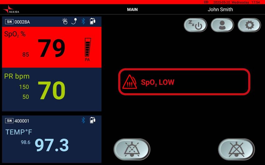
Table of Contents
Disclaimer....................................................................................................................... 1
Guide to Symbols ........................................................................................................... 3
Welcome ........................................................................................................................ 5
     GA1000S Main Elements........................................................................................ 5
     GA1000S Function.................................................................................................. 6
     GA1000S Intended Use .......................................................................................... 6
Precautions for Use ........................................................................................................ 7
Device Components ....................................................................................................... 8
Device Overview ............................................................................................................ 9
Device Setting Up ......................................................................................................... 14
Device Pairing............................................................................................................... 15
     Automatic Pairing................................................................................................. 15
     Pairing with a new Aulisa sensor module ............................................................ 15
Device Verification ....................................................................................................... 16
     Verify the device function .................................................................................... 16
     Verify the alarm function BEFORE each use ........................................................ 16
Device Power Off.......................................................................................................... 17
Device Powering........................................................................................................... 17
Alarms and Limits......................................................................................................... 18
     Alarm Features ..................................................................................................... 18
     Alarm Limits ......................................................................................................... 22
     Alarm Delay Feature (for Oximeter Module only) ............................................... 26
Care and Maintenance ................................................................................................. 27
Troubleshooting ........................................................................................................... 28
Manufacturer’s Declaration ......................................................................................... 29
FCC Compliance ........................................................................................................... 33
Service, Support, and Warranty ................................................................................... 35
Privacy Policy................................................................................................................ 36
     Our Policy ............................................................................................................. 36
     Changes ................................................................................................................ 37
Specifications ............................................................................................................... 44
Parts and Accessories................................................................................................... 45

                                                                2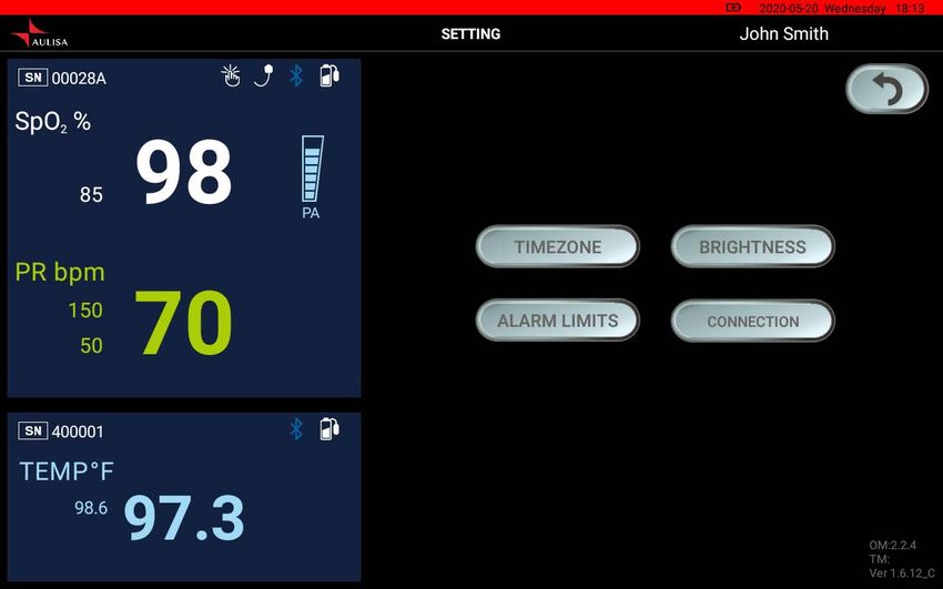
Guide to Symbols

                   3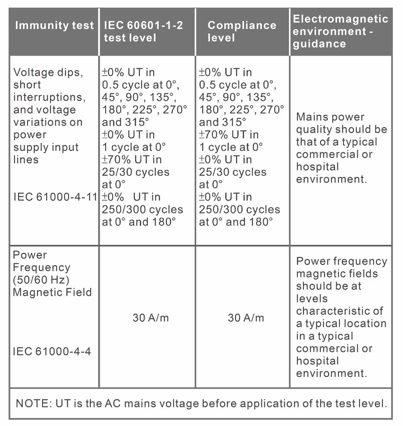
4
Welcome
This manual will help you get started with monitoring using Aulisa Guardian Angel®
Rx GA1000 Series Digital Vital Sign Monitoring System (“GA1000S”) by introducing
the Display Unit which is intended for use in conjunction with a variety of wearable
Aulisa sensor modules.
Refer to the Instructions for Use of Aulisa sensor module(s) for detailed instructions.
Adult/Pediatric Oximeter Module: 7MN00023-01
Infant Oximeter Module: 7MN00024-01
Thermometer Module: 7MN00025-01
GA1000S Main Elements
Display Unit – A self-contained tablet computer running Aulisa application
software wirelessly collects and displays vital sign data from the Aulisa sensor
module(s). It also generates alarms to alert users to technical errors or
physiological events.
Adult/Pediatric Oximeter Module – A wireless and reusable device worn on the
finger measures and transmits SpO2 and pulse rate data. It is composed of
Oximeter Box and Oximeter Sensor Cable.
Infant Oximeter Module – A wireless and reusable device worn on the foot
measures and transmits SpO2 and pulse rate data.
Thermometer Module – An adhesive device attached to the chest and armpit
measures and transmits body temperature data wirelessly. It comprises
Thermometer Box and Sensor Patch. It is intended for adults, pediatrics, and
infants.
5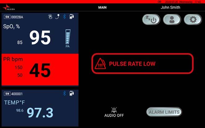
GA1000S Function

        Aulisa sensor module(s)

                                                          Display unit

The Aulisa sensor module(s) is a wearable device intended for vital signs detection
and physiological data transmission to the Display Unit via Bluetooth technology. The
Display Unit receives and displays physiological data as well as generates alarms for
technical errors or physiological events.

GA1000S Intended Use
The Guardian Angel® Rx GA1000 Series Digital Vital Sign Monitoring System is
indicated for use in measuring and displaying functional oxygen saturation of arterial
hemoglobin (SpO2), pulse rate (PR) and body temperature. The intended
environments of use are hospitals, medical facilities, home care, and subacute
environments. This system is a reusable device.

The Oximeter Module is indicated for spot-checking and/or continuous monitoring of
SpO2 and PR for adult, pediatric, and infant patients during non-motion and under
well-perfused conditions.

The Thermometer Module is indicated for continuous armpit body temperature
monitoring for adult, pediatric, and infant patients.

 NOTE: The GA1000S may come with different Aulisa sensor module(s) resulting in
 different intended uses.

                                          6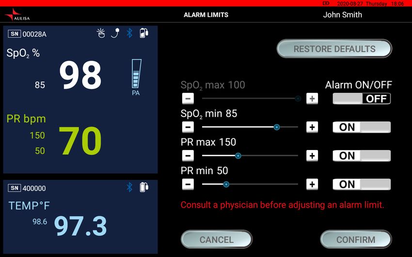
Precautions for Use
1.    This device is not a replacement for a caregiver nor a substitution for physician
      supervision. It is intended only as an adjunct in patient assessment and must be
      used in conjunction with other methods of assessing clinical signs and
      symptoms.
2.    Use this device only within its designated range (approximately 32.8 feet (10
      meters)— spherical radius— from Aulisa sensor module(s) to this device).
      Moving outside this range may cause missing, lost, and/or inaccurate data.
3.    This device readings may be affected by the use of an electrosurgical unit.
4.    If this device fails to respond as described, discontinue use until the situation is
      corrected by qualified personnel.
5.    As with all medical equipment, carefully route all cables to reduce the possibility
      of entanglement, strangulation, or injury to the patient.
6.    Be careful with small parts that can be removed from the device and swallowed,
      such as port covers. They are hazardous to children.
7.    Do not use in or around water or any other liquid when AC power adaptor is
      used.
8.    Only use this device with charging adaptors provided by Aulisa.
9.    Do not immerse any part of the device in any liquids.
10.   Do not subject the device to extreme hot or cold temperatures, humidity, or
      direct sunlight.
11.   Follow local governing ordinances and recycling instructions regarding disposal
      or recycling of the device and device components, including batteries.
12.   This device complies with International Standard IEC 60601-1-2: 2014 for
      electromagnetic compatibility for medical electrical equipment and/or systems.
      This standard is designed to provide reasonable protection against harmful
      interference in a typical medical installation. However, because of the
      proliferation of radio-frequency transmitting equipment and other sources of
      electrical noise in healthcare and other environments, it is possible that high
      levels of interference due to close proximity or strength of a source might
      disrupt the device's performance.
13.   Radios and cell phones or similar devices can affect the wireless connection of
      the device and must be kept at least 6.5 feet (2 meters) away from the device.
14.   System connection failure (Bluetooth wireless connection) may result in loss of
      data transfer.

                                            7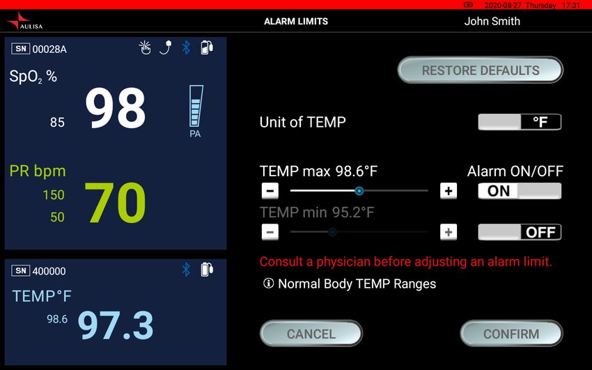
Device Components
           Display Unit with Aulisa application software

    Display Unit Stand              Display Unit Charging Adapter (Type-C)

                                8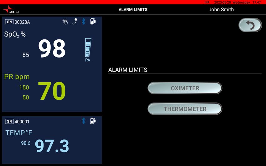
Device Overview
The Display Unit features a 10 1" LCD multi-touch display with Bluetooth technology.
The Display Unit displays real-time vital signs measured by Aulisa sensor module(s).

The Display Unit will display informational text messages, alarm text messages, and
beep made audible upon an alarm condition trigger event.

 NOTE: It is recommended that the Display Unit be placed on the Display Unit Stand.
 NOTE: Close the cover of charging port when the charging adapter is not in use.

Following tables describe the indicators and controls displayed on the Display Unit.

                           Display Icons and Indicators
       Indicator                  Name             Description
                                                   This icon identifies the window
  SpO2 %                     Blood Oxygen          showing the functional blood
                                                   oxygen saturation in percent.
                                                   This icon identifies the window
 PR bpm                        Pulse Rate
                                                   showing the pulse rate in bpm.
                                                   This icon identifies the window
 TEMP°F                   Body Temperature         showing the body temperature
                                                   in either °C or °F.
                                                   Displayed when the measured

        Hi                 High temperature        temperature is higher than
                                                   107.6°F (42.0°C).

                                            9
Displayed when the measured
Lo Low temperature temperature is lower than
89.6°F (32.0°C).
When the vital signs cannot be
measured, the Display Unit
No data
shows dashes “- - -” in each of
the vital sign windows.
This icon displays whether the
Aulisa sensor module(s) and the
Bluetooth
Display Unit are connected via
Connection Status
Bluetooth. It will turn blue once
the pairing succeeds.
Pulse Amplitude This icon displays the pulse
(PA) signal strength.
This icon displays whether
there is a finger inserted in the
Adult/Pediatric Oximeter
Measurement Site
Module.
Status
A system alarm will be
displayed on the Display Unit if
no fingers are detected.
This icon displays whether the
Infant Oximeter Module is
attached to the foot. A system
Measurement
alarm will be displayed on the
Site Status
Display Unit if no contact is
detected between the sensor
and the foot.
This animated icon detects
Motion Indicator excessive motion of the
measurement site.
This icon indicates whether the
Oximeter Sensor Cable is
Sensor Cable
connected to the Oximeter Box.
Connection Status
A system alarm will be
displayed on the Display Unit if
10the cable is disconnected.
These icons signify the battery
level of the Display Unit.
Battery Level of A medium priority system alarm
Display Unit will be displayed on the Display
Unit when the Display Unit
battery level is low.
These icons signify the battery
level of Aulisa sensor module(s)
Battery Level of at Full, Medium, or Low.
Aulisa sensor A medium priority system alarm
module(s) will be displayed on the Display
Unit when the battery level is
low.
This icon identifies an alarm
condition exists.
Alarm Indicator
“!!!” represents high priority.
“!!” represents medium priority.
This icon indicates that the
alarm is turned off for the
Alarm Off
corresponding physiological
condition.
This icon indicates that the
Audio Paused alarm audio is silenced for 2
minutes.
This icon indicates that the
Audio Off alarm audio is silenced
permanently.
Software Control Buttons
Button Function Description
Tap on this button on the MAIN
System Settings screen to access the setting
menu of the system.
Tap on this button on the MAIN
screen to edit profile, including
Edit Profile
name, weight, gender, date of
birth, and location.
11This button appears on the
MAIN screen when the system
is disconnected. Tap on the
button to force the
system to pair.
Device Pairing
NOTE: The Aulisa sensor
module(s) must be placed
within 32.8 feet (10 meters) to
the Display Unit.
Tap on this button on the MAIN
screen to let the Display Unit
enter sleep mode. To wake up
Sleep Mode
the Display Unit, tap on the
blank screen and use finger to
swipe to the right.
Return to Previous Tap on this button to return to
Screen the previous page.
In the Setting menu, tap on this
Set Timezone button to select the correct
timezone.
In the Setting menu, tap on this
Set Display
button to set the brightness of
Brightness
the display.
In the Setting menu, tap on this
button to adjust the alarm
limits for each Aulisa sensor
module.
Set Alarm Limits
NOTE: The alarm limits are
adjustable only when the
wireless connection is
established.
Tap on this button to restore
Restore Default
alarm limits to manufacture-
Alarm Settings
configured values.
In the Setting menu, tap on this
Establish Pairing
button and scan the barcode
12on the Aulisa sensor module(s)
to manually pair with the
Display Unit.
This button appears when an
alarm is triggered. Tap on the
button to temporarily silence
Pause Alarm Audio
the alarm audio of the current
triggered alarm event for 2
minutes.
The button appears when an
alarm is triggered. Tap on the
Turn Off Alarm
button to permanently silence
Audio
the alarm audio of the current
triggered alarm event.
The button appears when the
Infant Oximeter Module is
Standby detached from the foot. Tap
on the button to return to the
“Before You Start” page.
The button appears when the
Bluetooth is disconnected and
the alarm is triggered. Tap on
Clear Bluetooth
the button to clear the alarm
Alarm Condition
of “BLUETOOTH
DISCONNECTED OR POWER
OFF”.
13Device Setting Up
Before you begin your monitoring session, unpack the Display Unit and become
familiar with its parts.
Step 1: Set up the Aulisa sensor module(s).
NOTE: Refer to the Aulisa sensor module(s) Instructions for Use for setting up
instructions.
Step 2: Connect the charging adaptor to the Display Unit and a power outlet.
Step 3: Press and hold the Power button for at least three (3) seconds to turn on the
Display Unit.
CAUTION!!! Always keep the Display Unit plugged in.
CAUTION!!! Do not plug the adaptor into a switched outlet to prevent accidental
switching power off.
Step 4: Wait for the wireless connection between the Display Unit and the Aulisa
sensor module(s) to be established. Once connected, the vital signs and the
Aulisa sensor module(s) status information will appear on the MAIN screen.
NOTE: Refer to “Device Pairing” section below for more information.
NOTE: The Aulisa sensor module(s) must be used within 32.8 feet (10 meters) to the
Display Unit.
NOTE: The Bluetooth connection status icon will turn blue once the pairing succeeds.
NOTE: Verify System Operation before use. (See “Device Verification” section for more
information.)
14Device Pairing
Automatic Pairing
The Display Unit automatically detects and connects to the Aulisa sensor module(s)
from the same starter kit. If the Bluetooth connection is not established
automatically, press "PAIR" button on the MAIN screen of the Display Unit to force
the system to pair.
NOTE: The Aulisa sensor module(s) must be placed within 32.8 feet (10 meters) to the
Display Unit.
NOTE: The Bluetooth connection status icon will turn blue once the pairing succeeds.
NOTE: The power LED on the Aulisa sensor module(s) will blink green when pairing
succeeds, and data transmission starts.
Pairing with a new Aulisa sensor module
Follow the below instructions to manually set up the pairing of a new Aulisa sensor
module.
Step 1: In the Setting menu, select “PAIRING".
Step 2: Scan the QR Code or key in the serial number located on the Aulisa sensor
module(s).
Step 3: Press “CONFIRM” if the serial number (SN) displayed matches with the one
on the Aulisa sensor module(s).
Step 4: Power on the designated Aulisa sensor module(s).
NOTE: The power LED on the Aulisa sensor module(s) lights green when the power is
ON.
Step 5: To confirm that the process was successful, ensure that the Bluetooth
connection status icon on the MAIN screen of the Display Unit is lit blue.
NOTE: The Aulisa sensor module(s) remains paired with the Display Unit until the serial
number is deleted from the list.
15Device Verification
Verify the device function
Step 1: Set up the system. Refer to the Aulisa sensor module(s) Instructions for Use
for setting up instructions.
Step 2: Make sure Aulisa sensor module(s) is worn on or attached to the right place
firmly.
Step 3: Verify that the Bluetooth connection status icon on the Display Unit is blue
and the status indicator on Aulisa sensor module(s) is blinking green.
Step 4: Verify that the vital sign readings are displayed.
Verify the alarm function BEFORE each use
Step 1: Set up the system. Refer to the Aulisa sensor module(s) Instructions for Use
for setting up instructions.
Step 2: Ensure the Bluetooth connection is established. (See “Device Pairing”
section.)
Step 3: Set the alarm limit lower or higher than the displayed value.
Step 4: Verify that an alarm message is displayed and that an alarm audio is
generated. (See “Troubleshooting” section if an alarm message and audio
signal is not generated.)
Step 5: Press on the "PAUSE AUDIO" button to temporarily silence for 2 minutes.
Step 6: After alarm signal is regenerated, press on the "AUDIO OFF" button to
silence permanently the alarm signal.
16Device Power Off
Step 1: Press the Power button for at least three (3) seconds until a message
displayed.
Step 2: Choose “Power off” to turn off the Display Unit.
NOTE: You may also tap on the “SLEEP” button to enter the sleep mode.
Device Powering
The Display Unit is meant to be used with the charging adaptor ALWAYS plugged in. If
the Display Unit is disconnected from the charging adaptor accidentally, proceed
with the following steps to charge and power the Display Unit. The Display Unit will
alert the user when the Display Unit itself is low on battery.
Step 1: Plug the Type-C end of the charging adaptor into the Display Unit.
Step 2: Attach the wall adaptor to a power outlet.
Step 3: Place the Display Unit on the stand provided.
CAUTION!!! Only use adaptors supplied or manufactured by Taiwan Aulisa Medical
Devices Technologies, Inc.
17Alarms and Limits
Alarm Features
The Display Unit provides high and medium priority audible and visual alarms. The
visual alarm is indicated by the alarm window on the screen of the Display Unit.
Audio alarms will sound from the speakers on the Display Unit.
NOTE: The volume for audio alarms cannot be adjusted.
High Priority Alarms
High priority alarms are those that require immediate attention to the person
being monitored, including SpO2, pulse rate, and temperature alarms. On the
Display Unit, high priority alarms are indicated with rapid blinking vital sign
readings in red color and with alarm text message when alarm limits are met or
exceeded. (See figure below.)
NOTE: Alarm LED indicator on the Oximeter Module will blink red along with displays
on the Display Unit.
18High priority audio alarms are: 3 beeps, short pause, 2 beeps, short pause, 3
beeps, short pause, 2 beeps, and 5-second pause. This sequence repeats until
the alarm is cleared or silenced.
Tap on ʻʻPAUSE AUDIOʼʼ button to pause the alarm audio for 2 minutes. Tap on
ʻʻAUDIO OFFʼʼ button to permanently silence the alarm audio.
See “Alarm Limits” section to learn adjusting the alarm limit.
Medium Priority Alarms
Medium priority alarms are those that signal potential problems with the
equipment or other non-life-threatening situations. On the Display Unit, medium
priority alarms are indicated with slow blinking yellow displays and with alarm
text message. (See figure below.)
19NOTE: The following table describes alarm conditions and visual indicators.
Alarm Condition Visual Indicator
(Medium Priority Alarm)
Oximeter Sensor Probe Detached from the Finger The Oximeter Module blinks
Oximeter Module Battery Low yellow along with blinking
Oximeter Sensor Cable Detached yellow displays and alarm text
Oximeter Module Detection Error message on the Display Unit.
Display Unit Battery Low On the Display Unit, it blinks
Thermometer Battery Low yellow displays and alarm text
Oximeter Module Data Update Period Exceeds message.
Limit (More Than Half A Minute)
Bluetooth Disconnected
Medium priority audio alarms are: 3 beeps and 25-second pause. This sequence
repeats until the alarm is cleared or silenced.
Tap on “PAUSE AUDIO” button to pause the alarm audio for 2 minutes. Tap on
“AUDIO OFF” button to permanently turn off the alarm audio.
See “Alarm Limits” section to learn adjusting the alarm limit.
20Multiple Alarms
When there are high and medium priority alarms triggered simultaneously, the
system will display all the alarm text messages but will only sound the high
priority alarm.
CAUTION!!! Silencing alarms does not mean the situation has been resolved.
CAUTION!!! Tapping on “AUDIO OFF” button will permanently silence the alarm audio
of the current triggering alarm event.
CAUTION!!! A potential hazard exists if different alarm presets are used for the same or
similar equipment in any single area.
CAUTION!!! Do not plug a headphone into headphone jack of the Display Unit, as this
will significantly reduce the volume of alarm audio.
21Alarm Limits
Follow the instructions below to review or set alarm limits.
Step 1: Ensure the Bluetooth connection is established. (See “Device Pairing”
section.)
Step 2: Tap on "SETTING" button on the MAIN screen, and then tap on “ALARM
LIMITS” button. Select the designated Aulisa sensor module.
22NOTE: Alarm limits can be adjusted only when the Aulisa sensor module(s) is paired
with the Display Unit.
NOTE: In an alarm event, ʻʻALARM LIMITSʼʼ button will appear after you select "AUDIO
PAUSE" button or "AUDIO OFF" button.
Step 3: To turn alarms on or off, tap on ʻʻON/OFFʼʼ button. (Turn on the alarm before
adjusting the value.)
Step 4: Tap on ʻʻ + ʼʼ or ʻʻ– ʼʼ buttons or drag the ʻʻseekbarʼʼ to adjust the values OR
tap on “RESTORE DEFAULTS” to restore alarm limits to manufacturer
configured values.
23NOTE: SpO2 max limit is turned off by default.
NOTE: There is no alarm setting for pulse amplitude.
NOTE: TEMP min limit is turned off by default.
NOTE: Select designated Unit of TEMP, °C or °F, before adjusting the alarm limits.
CAUTION!!! A potential hazard exists if different alarm presets are used for the same or
similar equipment in any single area.
CAUTION!!! When turned off, the alarms will no longer be displayed or sound. Follow
the instructions above to turn on the alarms.
CAUTION!!! Consult a physician about the appropriate vital sing limits for the user
before adjusting an alarm.
24NOTE: The minimum alarm limit cannot exceed the maximum alarm limit, even if the
maximum alarm limit is turned off. For example, if the maximum SpO2 limit is turned
off but was previously set at 90%, the minimum SpO2 limit cannot be set higher than
90%. If you want to set minimum SpO2 limit at 90%, turn on the maximum SpO2 limit,
set it above 90% and turn it off again as you wish.
NOTE: The following table describes the default settings, adjustment ranges, and
intervals.
Adjustment Adjustment
High Priority Alarm Factory Default
Options Interval
SpO2
Off Off, 85-100% 1%
Upper Alarm Limit
SpO2
85% Off, 50-95% 1%
Lower Alarm Limit
Adult/
Pulse Rate 150 bpm
Pediatric Off, 75-275 bpm 1 bpm
Upper Alarm Limit
Infant 200 bpm
Adult/
Pulse Rate 50 bpm
Pediatric Off, 30-110 bpm 1 bpm
Lower Alarm Limit
Infant 75 bpm
Adult/
Temperature 98.6°F (37°C) Off, 89.6-107.6°F 0.1°F
Pediatric
Upper Alarm Limit (32 to 42°C) (0.1°C)
Infant 99.3°F (37.4°C)
Temperature Off, 89.6-107.6°F 0.1°F
Off
Lower Alarm Limit (32 to 42°C) (0.1°C)
Step 5: Tap on ʻʻCONFIRMʼʼ to save the alarm limits.
CAUTION!!! The new ALARM LIMITS do not go into effect until the “CONFIRM” button is
tapped.
NOTE: The upper and lower alarm limits appear as small-sized numbers next to the
measured value.
25Alarm Delay Feature (for Oximeter Module only)
In the traditional alarm management system, upper and lower alarm limits are set so
alarms are issued at specific SpO2 levels. When the SpO2 level fluctuates near an
alarm limit, each breach will trigger an alarm. This system monitors the gradient, the
depth and the duration of SpO2 reduction as the factors to determine the alarm
triggering delay. Therefore, it helps to distinguish between major clinical events and
minor and brief SpO2 alarm limit violations that may trigger an alarm.
NOTE: The following table lists the alarm triggering delay statistics for SpO2 Low Alarm
Limit.
SpO2 Low Average Delay Maximum Delay
Alarm Limit (seconds) (seconds)
≥ 90 50 74
86 - 90 16 20
81 - 85 6 7
76 - 80 4 6
≤ 75 4 5
Likewise, when the pulse rate fluctuates near an alarm limit, each breach will trigger
an alarm. With the pulse rate alarm delay feature, this system allows a period of
threshold violation of 5 seconds before an alarm is triggered. Thus, it greatly reduces
alarms reported for minor and brief alarm limit violations.
NOTE: A countdown timer and "AUDIO OFF" button will be displayed on the MAIN
screen when the alarm limit has been breached and the alarm is being delayed. The
alarm will be delayed until the timer counts down to zero.
26Care and Maintenance
The advanced digital circuitry within the Display Unit requires no calibration or
periodic maintenance. Field service or repair of this system is not possible. Do not
attempt to open the case. Opening the Display Unit will cause damage and void the
warranty. If the Display Unit is not functioning properly, see “Troubleshooting”
section for more information.
For care and maintenance of Aulisa sensor module(s), refer to the Aulisa sensor
module(s) Instructions for Use for additional instructions.
27Troubleshooting
Problem Possible Solution
Cannot turn on the Display 1. Press and hold the Power button for at
Unit least three (3) seconds.
2. Make sure the power cord is properly
connected at both ends.
Unable to obtain a reading 1. Make sure the Aulisa sensor module(s) is
within 32.8 feet (10 meters) spherical
radius to the Display Unit.
2. Verify the system’s wireless connection.
3. Check the Display Unit for any alarm
messages.
The Display Unit is in Alarm 1. Wait for two (2) minutes and alarm tones
mode, but no audible alarms will automatically re-engage.
can be heard. 2. Make sure no headphone is plugged in.
Cannot establish 1. Make sure the Aulisa sensor module(s) is
system connection within 32.8 feet (10 meters) spherical
radius to the Display Unit.
2. Turn off the system and retry.
Refer to the Aulisa sensor module(s) Instructions for Use for additional
troubleshooting.
If these solutions do not correct the problem, please contact your distributor, or
contact Aulisa by going online at www.aulisa.com under "Contact Us".
CAUTION!!! This system is a precision electronic instrument and must be repaired by
knowledgeable and specially trained Aulisa personnel only. Do not attempt to open the
case or repair the electronics.
28Manufacturer’s Declaration
Refer to the following table for specific information regarding compliance to IEC
60601-1-2 for this device.
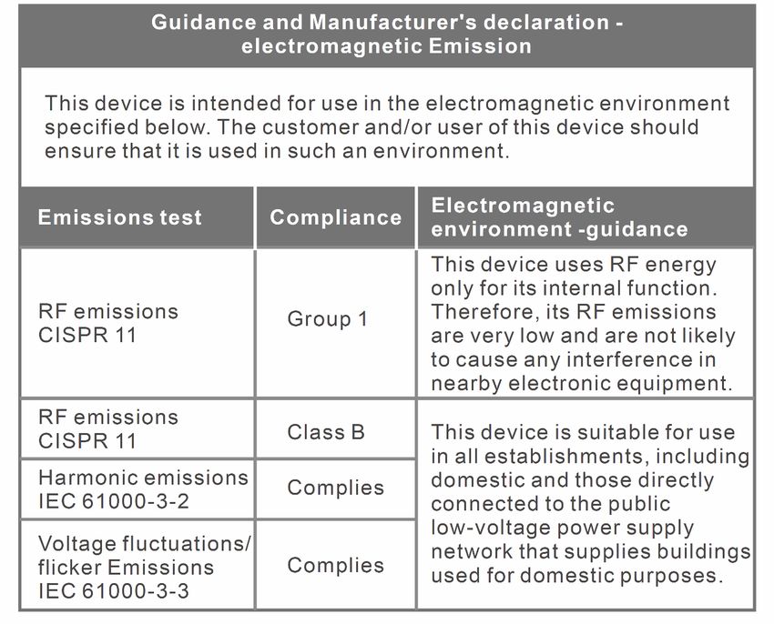
Guidance and manufacturer's declaration – electromagnetic emissions - for all
EQUIPMENT and SYSTEMS
29Guidance and manufacturer's declaration – electromagnetic immunity - for all
EQUIPMENT and SYSTEMS
3031
Guidance and manufacturer's declaration – electromagnetic immunity - for
EQUIPMENT and SYSTEMS that are not LIFE-SUPPORTING

                                       32
FCC Compliance
Declaration of Conformity with FCC for Electromagnetic Compatibility
This device complies with Part 15 of the FCC Rules. Operation is subject to the
following two conditions: (1) this device may not cause harmful interference, and (2)
this device must accept any interference received, including interference that may
cause undesignated operation.
Federal Communications Commission (FCC) Notice
This equipment has been tested and found to comply with the limits for a class B
digital device, pursuant to part 15 of the FCC Rules. These limits are designed to
provide reasonable protection against harmful interference in a residential
installation. This equipment generates, uses, and can radiate radio frequency energy.
If not installed and used in accordance with the instructions, it may cause harmful
interference to radio or television reception, which can be determined by turning the
equipment off and on. The user is encouraged to try to correct the interference by
one or more of the following measures:
(1) Reorient or relocate the receiving antenna.
(2) Increase the separation between the equipment and receiver.
(3) Connect the equipment into an outlet on a circuit different from that to which the
receiver is connected.
(4) Consult the dealer or an experienced radio/TV technician for help.
The device is designed and manufactured not to exceed the emission limits for
exposure to radio frequency (RF) energy set by the Federal Communications
Commission of the U.S. Government. These limits are part of comprehensive
guidelines and establish permitted levels of RF energy for the general population.
The guidelines are based on the safety standards previously set by both U.S. and
international standards bodies.
This equipment has been shown to be capable of compliance for localized specific
absorption rate (SAR) for uncontrolled environment/ general population exposure
limits specified in ANSI/IEEE Std. C95.1-1992 and has been tested in accordance with
the measurement procedures specified in IEEE Std. 1528-200X (Draft 6.5, January
2002).
FCC Radiation Exposure Statement
This EUT is compliance with SAR for general population/uncontrolled exposure limits
in ANSI/IEEE C95.1-1999 and had been tested in accordance with the measurement
33methods and procedures specified in OET Bulletin 65 Supplement C. The highest
reported SAR for the device is 0.116 W/kg.
When suing IEEE 802.11a wireless LAN, this product is restricted to indoor use, due
to its operation in the 5.15 to 5.25GHz frequency range. The FCC requires this
product to be used indoors for the frequency range of 5.15 to 5.25GHz to reduce the
potential for harmful interference to co channel mobile satellite systems. High power
radar is allocated as the primary user of the 5.25 to 5.35GHz and 5.65 to 5.85GHz
bands. These radar stations can cause interference with and/or damage to this
device.
CAUTION!!! No modifications to this device are allowed that in any way affect or alter
its antenna or antenna configuration.
34Service, Support, and Warranty
Taiwan Aulisa Medical Devices Technologies, Inc. (“Aulisa”) warrants to the purchaser
that each of Aulisa's product will be free from material defect for a period of one
year from the date of purchase (the “Warranty Period”), and Aulisa will repair or
replace at its discretion, free of charge, each Aulisa's product found to be materially
defective during the Warranty Period and for which Aulisa has been notified during
the Warranty Period (the “Warranty”). This Warranty shall be the sole and exclusive
remedy by the purchaser for the Aulisa product delivered to the purchaser,
irrespective whether such remedy is under contract, tort, or by law.
Aulisa's obligation under the Warranty is only if (i) Aulisa has received written notice
of the warranty claim within the Warranty Period, (ii) purchaser has returned the
product to Aulisa in accordance with instructions provided on Aulisa's support
webpage, and (iii) Aulisa has verified that the product is defective. Aulisa warrants a
replacement or repaired product only for products purchased from authorized
resellers and only for the unexpired term of the Warranty Period for the defective
product.
A return merchandise authorization (“RMA”) and its associated RMA number is
required before any product can be returned to Aulisa. To obtain this return
authorization number, please contact Aulisa Customer Support by going online at
www.aulisa.com under "Contact Us".
Under this Warranty, the purchaser is responsible for the cost of delivery of the
product to Aulisa's place of repair as designated by Aulisa, and Aulisa is responsible
for the cost of delivery back to the purchaser. Aulisa reserves the right to charge a fee
for a warranty repair request on an Aulisa product that is found to be within
specifications and without material defect.
35Privacy Policy
This Privacy Policy was last updated on March 22, 2019.
Our Policy
This privacy policy applies to personal information collected by Taiwan Aulisa Medical
Devices Technologies, Inc. (“Aulisa”, “we”, “us” and/or “our”) from users of the Aulisa
remote monitoring devices (the “Devices”). “Personal Information” includes any
information that can be used on its own or with other information to identify or
contact a single person or to identify an individual in context. If we can link particular
information (directly or indirectly) to an individual, we will consider this information
“Personal Information,” and we will protect it.
WE AT AULISA VALUE KEEPING YOUR PERSONAL INFORMATION CONFIDENTIAL AND
USING IT SOLELY IN THE CONTEXT OF OUR MISSION TO PROVIDE CONTINUOUS
MONITORING OF VITALS IN ORDER TO AID PEOPLE BEING MONITORED, HEALTHCARE
PROVIDERS (“PROVIDERS”), AND CAREGIVERS MAKE INFORMED DECISIONS ABOUT
YOUR CARE.
THE PERSONAL INFORMATION WE COLLECT AND TRANSMIT MAY INCLUDE
HEALTHCARE INFORMATION, INCLUDING MEDICAL INFORMATION. THEREFORE, OUR
PRIVACY PRACTICES ARE INTENDED TO COMPLY WITH THE HEALTH INSURANCE
PORTABILITY AND ACCOUNTABILITY ACT (“HIPAA”). WE WILL MAINTAIN THE PRIVACY
OF YOUR HEALTH INFORMATION AS REQUIRED BY HIPAA AND THE REGULATIONS
PROMULGATED UNDER THAT ACT. FOR ADDITIONAL INFORMATION RELATED TO
YOUR HEALTHCARE INFORMATION, PLEASE CONTACT information@aulisa.com.
We believe that transparency about the use of your personal information is
important. In this privacy policy, we provide you detailed information about our
collection, use, maintenance, and disclosure of your personal information. The policy
explains what kind of information we collect, when and how we might use that
information, how we protect the information, and your rights regarding your
personal information.
Please read the following carefully to understand our views and practices regarding
your Personal Information and how we will treat it. For the purposes of Applicable
Data Protection Laws including the European Economic Area data protection law (the
“Data Protection Law”):
36Non-Provider Users: The data controllers are the Provider and Taiwan Aulisa Medical
Devices Technologies, Inc., No. 218-2, Chong Yang Rd., Nangang
Dist., 11573 Taipei City, Taiwan
Provider Users: The data controller is Taiwan Aulisa Medical Devices Technologies,
Inc., No. 218-2, Chong Yang Rd., Nangang Dist., 11573 Taipei City,
Taiwan
Data Protection Officer: Paul Liu
BY USING THE DEVICES, YOU ARE ACKNOWLEDGING THAT YOU HAVE READ AND
AGREE TO THE TERMS OF THIS PRIVACY POLICY. IF YOU DO NOT AGREE, PLEASE DO
NOT USE THE DEVICES AND DO NOT SUBMIT ANY INFORMATION TO US.
Access to and use of the Devices by a Provider who is an Aulisa customer (a
“Customer”) and such Customer's authorized users is subject to and governed by the
agreement between Aulisa and the applicable Customer executed by authorized
representatives of each party (the “Customer Agreement”). Aulisa may collect, use
and disclose information from a Customer and such Customer's authorized users as
set forth in the Customer Agreement. If you would like more information about the
Devices or becoming a Customer, please contact us at information@aulisa.com.
Changes
PLEASE NOTE THAT WE OCCASIONALLY UPDATE THIS PRIVACY POLICY AND THAT IT IS
YOUR RESPONSIBILITY TO STAY UP TO DATE WITH ANY AMENDED VERSIONS. IF WE
MODIFY THIS PRIVACY POLICY, WE WILL NOTIFY YOU OF THE CHANGES ON OUR
WEBSITE, AN IN-SERVICE NOTICE OR OTHER REASONABLE MEANS. YOU CAN STORE
THIS POLICY AND/OR ANY AMENDED VERSION(S) DIGITALLY, PRINT IT, OR SAVE IT IN
ANY OTHER WAY. ANY CHANGES TO THIS PRIVACY POLICY WILL BE EFFECTIVE
IMMEDIATELY UPON POSTING, AND SHALL APPLY TO ALL INFORMATION WE
MAINTAIN, USE AND DISCLOSE. IF YOU CONTINUE TO USE THE DEVICES FOLLOWING
SUCH NOTICE, YOU ARE AGREEING TO THOSE CHANGES.
Capitalized terms, if not defined in this Privacy Policy, are defined in the
documentation that came with your Devices.
37 What Information Do We Collect and Why?
Personal Data that You Provide Through the Devices
We collect Personal Information (e.g. demographic information) from you when you
voluntarily provide such information to us, use the Devices (including without
limitation, the software featured on the Devices and/or platforms), contact us with
inquiries, or use certain features of the Devices. We use this information to allow the
Devices to provide the information to you and/or your Provider.
In addition to demographic information, if you are a person being monitored, we
collect Health Data through the Devices. Such Health Data may include information
about your vital signs, health conditions, age, gender, weight, and height. We collect
this information to communicate information to your healthcare provider.
Primarily, the collection of your Personal Information assists us in providing a means
to track your vital signs in order to better enable you to communicate information
with caregivers and healthcare providers and be an active participant with those
providers in monitoring your care, tailoring interventions, and assessing treatment
outcomes. We may also use your Personal Information to (1) store data; (2) comply
with the law; (3) respond to requests from public and government authorities; (4) to
enforce our terms and conditions; (5) manage and improve our operations and
applications; (6) provide additional functionality; (7) protect our rights, privacy, safety
or property, and/or that of yours or others; and (8) allow us to pursue available
remedies or limit the damages we may sustain.
Failure to Provide Information
Providing your Personal Information is not statutorily or contractually mandated. If
you choose not to provide this information, we cannot monitor your vital signs, and
you will be unable to use our Devices.
Support Information
If you contact Aulisa for support or to lodge a complaint, we may collect technical or
other information from you. Such information will be used for the purposes of
troubleshooting, customer support, software updates, and improvement of the
Devices in accordance with this Privacy Policy. Calls with Aulisa may be recorded or
monitored for training, quality assurance, customer service, and reference purposes.
38Aggregated Personal Data: In an ongoing effort to better understand and serve our
customers, other users of the Devices, and communities of people with similar
health conditions, Aulisa may conduct research on its user demographics and
behavior based on the Personal Information we collect from you and the other
information provided to us. This research may be compiled and analyzed on an
aggregate basis, and Aulisa may share this research and related information in
aggregated, de-identified and/or anonymized format with its affiliates, agents and
other healthcare research and services entities, including without limitation
insurance and pharmaceutical companies. For the avoidance of doubt, this aggregate
information does not identify you personally. Aulisa may also disclose aggregated,
de-identified and/or anonymized information in order to describe our business and
the Devices to current and prospective business partners and Customers, and to
other third parties for other lawful purposes.
Where Is My Personal Information Stored And/Or Processed?
Information Aulisa collects through the Devices will be processed and/or stored on
secure third-party cloud-based servers or through a Wi-Fi network. All of the
information you share with us through the Devices is double-encrypted during
transmission using AES-128 data encryption as well as an Aulisa private encryption
method.
Will You Share My Personal Information With Anyone Else?
We consider your information to be a vital part of our relationship with you. There
are, however, certain circumstances in which we may share your Personal
Information with certain third parties without further notice to you. Those
circumstances are described below:
With Our Provider Customers: If you are a person being monitored, we will share
your Personal Information and Health Data with our Provider Customer(s) that
provide healthcare services to you. This will enable your Provider to track your
Health Data and combine such Health Data with other information about you that
your Provider obtains in providing healthcare services to you.
With Caregivers: If you are a person being monitored, family and/or friends may
view certain of your Personal Information and/or Health Data and related alerts.
In the Event of a Business Transfer: We might sell or buy businesses or assets. In the
event of a corporate sale, merger, reorganization, dissolution or similar event,
Personal Information may be part of the transferred assets.
39With Related Companies: We may also share Personal Information with Aulisa
Related Companies for purposes consistent with this Privacy Policy.
With Our Agents, Consultants and Related Third Parties: Aulisa, like many
businesses, sometimes hires other companies to perform certain business-related
functions. Examples of such functions include data hosting and billing management.
When we employ another entity to perform a function of this nature, we only
provide the entity with the information that it needs to perform its specific function.
To Meet Our Legal Requirements: We may disclose your Personal Information if
required to do so by law or if we have a good faith belief that such action is
necessary to (i) comply with a legal obligation, (ii) protect and defend our rights or
property, (iii) act in urgent circumstances to protect the personal safety of you, us,
other users of the Devices or the public, or (iv) protect against legal liability.
NOTE: We may, from time to time, rent or sell aggregated data and/or other
information that does not contain any personal identifiers (i.e., if the information has
been anonymized by stripping out identifiers such as name, address, phone number,
etc.). The purpose of this type of disclosure is to allow research institutions to learn
more about symptoms associated with your medical condition(s).
How Long Will You Retain the Information?
We only store certain of your Personal Information for as long as you use the Devices
and up to five (5) years after you cease to use the Devices. At the end of this five-year
period, we will remove your Personal Information from our databases and will
request that our business partners remove your Personal Information from their
databases. However, once we disclose your Personal Information to third parties, we
may not be able to access that Personal Information any longer and cannot force the
deletion or modification of any such information by the parties to whom we have
made those disclosures. Written requests for deletion of Personal Information other
than as described should be directed to information@aulisa.com. We retain
anonymized data indefinitely.
How Do You Protect My Personal Information?
Aulisa is committed to protecting the security and confidentiality of Personal
Information. We use a combination of reasonable physical, technical, and
administrative security controls to maintain the security and integrity of your
Personal Information, to protect against any anticipated threats or hazards to the
40security or integrity of such information, and to protect against unauthorized access
to or use of such information in our possession or control that could result in
substantial harm or inconvenience to you. However, Internet data transmissions,
whether wired or wireless, cannot be guaranteed to be 100% secure. As a result, we
cannot guarantee the security of information you transmit to us. By using the
Devices, you are assuming this risk.
Safeguards
The information Aulisa collects and stores on secure servers is protected by a
combination of technical, administrative, and physical security safeguards, such as
authentication, encryption, backups, and access controls. If Aulisa learns of a security
concern, we may attempt to notify you and provide information on protective steps,
if available, through the e mail address that you have provided to us or other
reasonable notification. Depending on where you live, you may have a legal right to
receive such notices in writing.
NOTWITHSTANDING ANY OF THE STEPS WE TAKE, IT IS NOT POSSIBLE TO
GUARANTEE THE SECURITY OR INTEGRITY OF DATA TRANSMITTED OVER THE
INTERNET. THERE IS NO GUARANTEE THAT YOUR INFORMATION WILL NOT BE
ACCESSED, DISCLOSED, ALTERED, OR DESTROYED BY BREACH OF ANY OF OUR
PHYSICAL, TECHNICAL, OR ADMINISTRATIVE SAFEGUARDS. THEREFORE, WE DO NOT
AND CANNOT ENSURE OR WARRANT THE SECURITY OR INTEGRITY OF ANY
INFORMATION YOU TRANSMIT TO US AND YOU TRANSMIT SUCH INFORMATION AT
YOUR OWN RISK.
How Can I Protect My Personal Information?
We will NEVER send you an e-mail requesting confidential information such as
account numbers, or social security numbers, and you should NEVER respond to any
e-mail requesting such information. If you receive such an e-mail purportedly from
Aulisa, DO NOT RESPOND to the e-mail and DO NOT CLICK on any links and/or open
any attachments in the e-mail, and notify Aulisa support at information@aulisa.com.
You are responsible for taking reasonable precautions to safeguard the Device from
exposure to unauthorized third parties, and you are not permitted to circumvent the
use of required encryption technologies.
41EU DATA SUBJECT RIGHTS
If you are an EU data subject, you have the following rights under certain
circumstances:
to receive communications related to the processing of your personal data that
are concise, transparent, intelligible and easily accessible;
to be provided with a copy of your personal data held by us;
to request the rectification or erasure of your personal data held by us without
undue delay;
to request that we restrict the processing of your personal data (while we verify
or investigate your concerns with this information, for example);
to object to the further processing of your personal data, including the right to
object to marketing;
to request that your personal data be moved to a third party;
to receive your personal data in a structured, commonly used and machine-
readable format;
to lodge a complaint with a supervisory authority.
Where our processing of your Personal Information is based on consent, you have
the right to withdraw that consent without detriment at any time by contacting us at
information@aulisa.com.
You can also exercise the rights listed above at any time by contacting us at
information@aulisa.com.
How Can I Update, Correct Or Delete My Personal Information?
If you need to make changes or corrections to your information, you may make such
changes or corrections on the Device.
Information Submission By Minors
If the Device is being utilized by a minor, and the Devices are being used to monitor a
minor, you represent, warrant and covenant that by agreeing to the terms of this
Privacy Policy, you have the legal authority to accept this Privacy Policy on behalf of
such minor as the minor's parent or legal guardian. If you do not have such legal
authority, do NOT accept this Privacy Policy and do not use the Devices on behalf of
such minor.
42 How Can I Contact Aulisa?
If you have any questions or comments about this Privacy Policy, our practices, or our
Devices, please feel free to e-mail us at information@aulisa.com.
43Specifications
Display panel 10.1” IPS Touch Panel
Power Requirements
Mains 100-240V AC 50-60 Hz
DC Input 5V DC/AC adaptor
Internal Power
Battery Type 3.8V battery
Battery Life 2 hours of continuous operation
Dimensions 7.04” x 10.35” x 0.46”
(179mm x 263mm x 11.8mm)
Weight 21.87 oz (620g)
Alarm Sound Pressure 60dB
Ingress Protection IP22
Temperature
Operating +5°C to + 40°C
Storage/Transportation -25°C to + 70°C
Humidity
Operating 15% to 90% R.H. non-condensing
Storage/Transportation 10% to 93% R.H. non-condensing
Operating Altitude altitude ≤ 3 000 m
Atmospheric Pressure 700 hPa to 1013 hPa
Wireless Communication
Protocol Bluetooth 4.0
Range 32.8 feet (10 meters) spherical radius
Direction Bi-direction
Data rate Up to 100k Bps
Classifications per IEC 60601- 1
Type of Protection Class II, MOPP (on AC power)
Internally powered (on battery power)
Type of Protection Type BF-Applied Part
Mode of Operation Continuous
44Parts and Accessories
Parts and Accessories Model Number
Display Unit GA-DU0003
Display Unit Stand GA-SD0002
Charging Adaptor GA-CD0004
Refer to the Aulisa sensor module(s) Instructions for Use for more Aulisa sensor
module(s) information.
You may also contact your distributor or contact Aulisa by going online at
www.aulisa.com under "Contact Us".
CAUTION!!! Using accessories not by Taiwan Aulisa Medical Devices Technologies, Inc.
may result in inaccurate measurements. Always use parts and accessories by Taiwan
Aulisa Medical Devices Technologies, Inc.
7MN00021-01
45You can also read