User Manual 8-inch F-Range Inset Lights - UM-5015, Rev. 1.4, 2022/07/06 - ADB Safegate
←
→
Page content transcription
If your browser does not render page correctly, please read the page content below

8-inch F-Range Inset Lights

User Manual
UM-5015, Rev. 1.4, 2022/07/06

A.0 Disclaimer / Standard Warranty
CE certification
The equipment listed as CE certified means that the product complies with the essential requirements concerning safety and
hygiene. The European directives that have been taken into consideration in the design are available on written request to
ADB SAFEGATE.

ETL certification
The equipment listed as ETL certified means that the product complies with the essential requirements concerning safety and
FAA Airfield regulations. The FAA directives that have been taken into consideration in the design are available on written
request to ADB SAFEGATE.

All Products Guarantee
ADB SAFEGATE will correct by repair or replacement per the applicable guarantee above, at its option, equipment or parts
which fail because of mechanical, electrical or physical defects, provided that the goods have been properly handled and
stored prior to installation, properly installed and properly operated after installation, and provided further that Buyer gives
ADB SAFEGATE written notice of such defects after delivery of the goods to Buyer. Refer to the Safety section for more
information on Material Handling Precautions and Storage precautions that must be followed.
ADB SAFEGATE reserves the right to examine goods upon which a claim is made. Said goods must be presented in the same
condition as when the defect therein was discovered. ADB SAFEGATE furthers reserves the right to require the return of such
goods to establish any claim.
ADB SAFEGATE's obligation under this guarantee is limited to making repair or replacement within a reasonable time after
receipt of such written notice and does not include any other costs such as the cost of removal of defective part, installation
of repaired product, labor or consequential damages of any kind, the exclusive remedy being to require such new parts to be
furnished.
ADB SAFEGATE's liability under no circumstances will exceed the contract price of goods claimed to be defective. Any returns
under this guarantee are to be on a transportation charges prepaid basis. For products not manufactured by, but sold by
ADB SAFEGATE, warranty is limited to that extended by the original manufacturer. This is ADB SAFEGATE's sole guarantee and
warranty with respect to the goods; there are no express warranties or warranties of fitness for any particular purpose or any
implied warranties of fitness for any particular purpose or any implied warranties other than those made expressly herein. All
such warranties being expressly disclaimed.

Standard Products Guarantee
Products manufactured by ADB SAFEGATE are guaranteed against mechanical, electrical, and physical defects (excluding
lamps) which may occur during proper and normal use for a period of two years from the date of ex-works delivery, and are
guaranteed to be merchantable and fit for the ordinary purposes for which such products are made.

        Note
        See your sales order contract for a complete warranty description.
        Replaced or repaired equipment under warranty falls into the warranty of the original delivery. No new warranty
        period is started for these replaced or repaired products.

FAA Certified products manufactured by ADB SAFEGATE
ADB SAFEGATE L858 Airfield Guidance Signs are warranted against mechanical and physical defects in design or manufacture
for a period of 2 years from date of installation, per FAA AC 150/5345-44 (applicable edition).
ADB SAFEGATE LED products (with the exception of obstruction lighting) are warranted against electrical defects in design or
manufacture of the LED or LED specific circuitry for a period of 4 years from date of installation, per FAA EB67 (applicable
edition). These FAA certified constant current (series) powered LED products must be installed, interfaced and powered with
and through products certified under the FAA Airfield Lighting Equipment Program (ALECP) to be included in this 4 (four) year
warranty. This includes, but is not limited to, interface with products such as Base Cans, Isolation Transformers, Connectors,
Wiring, and Constant Current Regulators.

UM-5015, Rev. 1.4, 2022/07/06                                                                                                      iii
Copyright © ADB Safegate, All Rights Reserved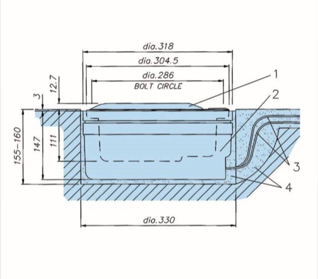
8-inch F-Range Inset Lights

        Note
        See your sales order contract for a complete warranty description.
        Replaced or repaired equipment under warranty falls into the warranty of the original delivery. No new warranty
        period is started for these replaced or repaired products.

Liability

                    WARNING
                    Use of the equipment in ways other than described in the catalog leaflet and the manual may result in personal injury,
                    death, or property and equipment damage. Use this equipment only as described in the manual.

ADB SAFEGATE cannot be held responsible for injuries or damages resulting from non-standard, unintended uses of its
equipment. The equipment is designed and intended only for the purpose described in the manual. Uses not described in the
manual are considered unintended uses and may result in serious personal injury, death or property damage.
Unintended uses, includes the following actions:

• Making changes to equipment that have not been recommended or described in this manual or using parts that are not
    genuine ADB SAFEGATE replacement parts or accessories.
• Failing to make sure that auxiliary equipment complies with approval agency requirements, local codes, and all applicable
    safety standards if not in contradiction with the general rules.
• Using materials or auxiliary equipment that are inappropriate or incompatible with your ADB SAFEGATE equipment.
• Allowing unskilled personnel to perform any task on or with the equipment.
©   ADB SAFEGATE BV
This manual or parts thereof may not be reproduced, stored in a retrieval system, or transmitted, in any form or by any means,
electronic, mechanical, photocopying, recording, nor otherwise, without ADB SAFEGATE BV's prior written consent.
This manual could contain technical inaccuracies or typographical errors. ADB SAFEGATE BV reserves the right to revise this
manual from time to time in the contents thereof without obligation of ADB SAFEGATE BV to notify any person of such
revision or change. Details and values given in this manual are average values and have been compiled with care. They are
not binding, however, and ADB SAFEGATE BV disclaims any liability for damages or detriments suffered as a result of reliance
on the information given herein or the use of products, processes or equipment to which this manual refers. No warranty is
made that the use of the information or of the products, processes or equipment to which this manual refers will not infringe
any third party's patents or rights. The information given does not release the buyer from making their own experiments and
tests.

iv
Copyright © ADB Safegate, All Rights Reserved
TABLE OF CONTENTS

1.0 Safety ....................................................................................................................................................................................... 1
     1.1 Safety Messages ........................................................................................................................................................................................................ 1
          1.1.1 Introduction to Safety ................................................................................................................................................................................. 2
          1.1.2 Intended Use .................................................................................................................................................................................................. 2
          1.1.3 Material Handling Precautions: Storage .............................................................................................................................................. 3
          1.1.4 Material Handling Precautions: Fasteners .......................................................................................................................................... 3
          1.1.5 Maintenance Safety ..................................................................................................................................................................................... 4
          1.1.6 Material Handling Precautions, ESD ..................................................................................................................................................... 4
          1.1.7 Arc Flash and Electric Shock Hazard ..................................................................................................................................................... 5
2.0 About this Manual ................................................................................................................................................................. 7
    2.1 How to work with the manual .............................................................................................................................................................................. 7
    2.2 Abbreviations and terms — AGL ......................................................................................................................................................................... 7
3.0 Introduction to 8-inch F- Range inset lights ....................................................................................................................... 9
     3.1 Common properties 8-inch lights ...................................................................................................................................................................... 9
     3.2 Specific properties of the FRC light ................................................................................................................................................................. 11
     3.3 Specific properties of the FTD light ................................................................................................................................................................. 12
     3.4 Specific properties of the FTZ light ................................................................................................................................................................. 14
4.0 Installation ............................................................................................................................................................................ 15
     4.1 Safety instruction — Fixing elements ............................................................................................................................................................. 15
     4.2 General recommendations regarding installation ..................................................................................................................................... 15
          4.2.1 Receiving, storage and unpacking ...................................................................................................................................................... 15
          4.2.2 Electrical connection ................................................................................................................................................................................. 15
          4.2.3 Base Earthing ............................................................................................................................................................................................... 16
     4.3 How to mount the light assembly? ................................................................................................................................................................. 16
          4.3.1 Use the correct fixing hardware ........................................................................................................................................................... 16
          4.3.2 Installation procedure .............................................................................................................................................................................. 16
     4.4 Adapter ring Installation ...................................................................................................................................................................................... 18
5.0 Maintenance ......................................................................................................................................................................... 19
    5.1 Overall maintenance — types and tasks ....................................................................................................................................................... 19
         5.1.1 In the field maintenance ......................................................................................................................................................................... 19
         5.1.2 Preventive maintenance — Part 1 ....................................................................................................................................................... 19
         5.1.3 Preventive maintenance — Part 2 ....................................................................................................................................................... 19
    5.2 Fixture and component related maintenance — detailed procedures .............................................................................................. 20
         5.2.1 How to open the light assembly .......................................................................................................................................................... 21
         5.2.2 How to lift the light fixture out of the base or adapter ring ..................................................................................................... 22
         5.2.3 How to replace a lamp ............................................................................................................................................................................. 23
         5.2.4 How to replace a filter .............................................................................................................................................................................. 25
         5.2.5 How to replace a prism ........................................................................................................................................................................... 25
         5.2.6 How to replace the optical assembly ................................................................................................................................................. 26
         5.2.7 How to replace the cable set assembly ............................................................................................................................................. 28
         5.2.8 How to close and test the light fixture .............................................................................................................................................. 29
    5.3 Product Troubleshooting ..................................................................................................................................................................................... 30
    5.4 Accessories ................................................................................................................................................................................................................ 31
         5.4.1 Tool case ........................................................................................................................................................................................................ 31
         5.4.2 Additional accessories ............................................................................................................................................................................. 32
         5.4.3 Fixing elements ........................................................................................................................................................................................... 32
6.0 Spare parts ............................................................................................................................................................................ 33
     6.1 Exploded views ........................................................................................................................................................................................................ 34
          6.1.1 8-inch F-Range FRC and FTD ................................................................................................................................................................ 34
          6.1.2 8-inch F-Range FTZ ................................................................................................................................................................................... 35
     6.2 Complete Fixtures ................................................................................................................................................................................................... 36
          6.2.1 Fixtures and main assemblies — part 1 ............................................................................................................................................ 36

UM-5015, Rev. 1.4, 2022/07/06                                                                                                                                                                                                        v
Copyright © ADB Safegate, All Rights Reserved
8-inch F-Range Inset Lights
TABLE OF CONTENTS
6.2.2 Fixtures and main assemblies — part 2 ............................................................................................................................................ 37
6.3 Fixing hardware kits ............................................................................................................................................................................................... 38
6.4 Components ............................................................................................................................................................................................................. 40
6.4.1 FRC, FTZ, FTD cover components ........................................................................................................................................................ 40
6.4.2 8-inch F-Range optical assemblies and lamps ............................................................................................................................... 41
6.4.3 8-inch F-range inset lights inner covers ........................................................................................................................................... 41
6.5 Screws used in F-Range 8-inch ......................................................................................................................................................................... 42
A.0 INTEROPERABILITY ............................................................................................................................................................. 43
B.0 POWER TABLE ...................................................................................................................................................................... 45
C.0 CABLE LOSS .......................................................................................................................................................................... 47
D.0 SUPPORT .............................................................................................................................................................................. 49
D.1 Telephoning Customer Service ......................................................................................................................................................................... 49
D.2 ADB SAFEGATE Website ...................................................................................................................................................................................... 49
D.3 Disposal ..................................................................................................................................................................................................................... 50
D.4 Recycling .................................................................................................................................................................................................................... 50
D.4.1 Local Authority Recycling ....................................................................................................................................................................... 50
D.4.2 ADB SAFEGATE Recycling ....................................................................................................................................................................... 50
vi
Copyright © ADB Safegate, All Rights ReservedList of Figures Figure 1: Fixture profile ......................................................................................................................................................................................................... 17 Figure 2: Mounting procedure ........................................................................................................................................................................................... 17 Figure 3: Installation drawing ............................................................................................................................................................................................. 18 Figure 4: Light opening procedure 1 ............................................................................................................................................................................... 21 Figure 5: Light opening procedure 2 ............................................................................................................................................................................... 21 Figure 6: light opening procedure 3 ................................................................................................................................................................................ 22 Figure 7: light opening procedure 4 ................................................................................................................................................................................ 22 Figure 8: Lifting procedure .................................................................................................................................................................................................. 23 Figure 9: Lamp replacement procedure 1 ..................................................................................................................................................................... 24 Figure 10: Lamp replacement procedure 2 ................................................................................................................................................................... 24 Figure 11: Filter replacement procedure ........................................................................................................................................................................ 25 Figure 12: Prism replacement procedure ....................................................................................................................................................................... 25 Figure 13: Optical assembly replacement procedure ............................................................................................................................................... 26 Figure 14: Lamp holder positioning procedure ........................................................................................................................................................... 27 Figure 15: Cable assembly replacement procedure .................................................................................................................................................. 28 Figure 16: Closing procedure 1 .......................................................................................................................................................................................... 29 Figure 17: Closing procedure 2 .......................................................................................................................................................................................... 29 Figure 18: 8-inch F-Range inset light - Exploded View 1 ........................................................................................................................................ 34 Figure 19: 8-inch F-Range inset light - Exploded View 2 ........................................................................................................................................ 35 UM-5015, Rev. 1.4, 2022/07/06 vii Copyright © ADB Safegate, All Rights Reserved
8-inch F-Range Inset Lights
List of Figures

viii
Copyright © ADB Safegate, All Rights Reserved
List of Tables

Table 1: Preventive maintenance tasks ........................................................................................................................................................................... 19
Table 2: Troubleshooting ...................................................................................................................................................................................................... 30
Table 3: Maintenance tools overview .............................................................................................................................................................................. 31
Table 4: Additional accessories overview ....................................................................................................................................................................... 32
Table 5: Fixtures and main assemblies of 8” F-Range inset lights; standard versions .................................................................................. 36
Table 6: Fixtures and main assemblies of 8” F-Range inset lights; special versions ...................................................................................... 37
Table 7: Fixing hardware kits of F-Range inset lights ................................................................................................................................................ 38
Table 8: Components and main assemblies of the 8-inch F-Range covers ...................................................................................................... 40
Table 9: Components of the 8-inch F-Range optical assemblies and lamps ................................................................................................... 41
Table 10: Components of the 8-inch F-range inset lights inner covers ............................................................................................................. 41
Table 11: Screws and references ........................................................................................................................................................................................ 42
Table 12: Interoperability matrix ........................................................................................................................................................................................ 43

UM-5015, Rev. 1.4, 2022/07/06                                                                                                                                                                                                  ix
Copyright © ADB Safegate, All Rights Reserved
8-inch F-Range Inset Lights
List of Tables

x
Copyright © ADB Safegate, All Rights Reserved
1.0 Safety
Introduction to Safety
This section contains general safety instructions for installing and using ADB SAFEGATE equipment. Some safety instructions
may not apply to the equipment in this manual. Task- and equipment-specific warnings are included in other sections of this
manual where appropriate.

1.1 Safety Messages

HAZARD Icons used in the manual
For all HAZARD symbols in use, see the Safety section. All symbols must comply with ISO and ANSI standards.
Carefully read and observe all safety instructions in this manual, which alert you to safety hazards and conditions that may
result in personal injury, death or property and equipment damage and are accompanied by the symbol shown below.

                    WARNING
                    Failure to observe a warning may result in personal injury, death or equipment damage.

                    DANGER - Risk of electrical shock or ARC FLASH
                    Disconnect equipment from line voltage. Failure to observe this warning may result in personal injury, death, or
                    equipment damage. ARC Flash may cause blindness, severe burns or death.

                    WARNING - Wear personal protective equipment
                    Failure to observe may result in serious injury.

                    WARNING - Do not touch
                    Failure to observe this warning may result in personal injury, death, or equipment damage.

                    CAUTION
                    Failure to observe a caution may result in equipment damage.

Qualified Personnel

                    Important Information
                    The term qualified personnel is defined here as individuals who thoroughly understand the equipment and its safe
                    operation, maintenance and repair. Qualified personnel are physically capable of performing the required tasks, familiar
                    with all relevant safety rules and regulations and have been trained to safely install, operate, maintain and repair the
                    equipment. It is the responsibility of the company operating this equipment to ensure that its personnel meet these
                    requirements.
                    Always use required personal protective equipment (PPE) and follow safe electrical work practice.

UM-5015, Rev. 1.4, 2022/07/06                                                                                                                  1
Copyright © ADB Safegate, All Rights Reserved
8-inch F-Range Inset Lights
Safety
1.1.1 Introduction to Safety
CAUTION
Unsafe Equipment Use
This equipment may contain electrostatic devices, hazardous voltages and sharp edges on components
• Read installation instructions in their entirety before starting installation.
• Become familiar with the general safety instructions in this section of the manual before installing,
operating, maintaining or repairing this equipment.
• Read and carefully follow the instructions throughout this manual for performing specific tasks and
working with specific equipment.
• Make this manual available to personnel installing, operating, maintaining or repairing this
equipment.
• Follow all applicable safety procedures required by your company, industry standards and
government or other regulatory agencies.
• Install all electrical connections to local code.
• Use only electrical wire of sufficient gauge and insulation to handle the rated current demand. All
wiring must meet local codes.
• Route electrical wiring along a protected path. Make sure they will not be damaged by moving
equipment.
• Protect components from damage, wear, and harsh environment conditions.
• Allow ample room for maintenance, panel accessibility, and cover removal.
• Protect equipment with safety devices as specified by applicable safety regulations
• If safety devices must be removed for installation, install them immediately after the work is
completed and check them for proper functioning prior to returning power to the circuit.
Failure to follow this instruction can result in serious injury or equipment damage
Additional Reference Materials
Important Information
• IEC - International Standards and Conformity Assessment for all electrical, electronic and related technologies.
• IEC 60364 - Electrical Installations in Buildings.
• FAA Advisory: AC 150/5340-26 (current edition), Maintenance of Airport Visual Aid Facilities.
• Maintenance personnel must refer to the maintenance procedure described in the ICAO Airport Services Manual,
Part 9.
• ANSI/NFPA 79, Electrical Standards for Metalworking Machine Tools.
• National and local electrical codes and standards.
1.1.2 Intended Use
CAUTION
Use this equipment as intended by the manufacturer
This equipment is designed to perform a specific function, do not use this equipment for other purposes
• Using this equipment in ways other than described in this manual may result in personal injury, death
or property and equipment damage. Use this equipment only as described in this manual.
Failure to follow this instruction can result in serious injury or equipment damage
2
Copyright © ADB Safegate, All Rights Reserved1.1.3 Material Handling Precautions: Storage
CAUTION
Improper Storage
Store this equipment properly
• If equipment is to be stored prior to installation, it must be protected from the weather and kept free
of condensation and dust.
Failure to follow this instruction can result in equipment damage
1.1.4 Material Handling Precautions: Fasteners
DANGER
Foreign Object Damage - FOD
This equipment may contain fasteners that may come loose - torque properly.
• Only use fasteners of the same type as the one originally supplied with the equipment.
• Use of incorrect combination of gaskets, bolts and nuts can create severe damages to the product
installation and create safety risk .
• You need to know what base the light fixture will be installed in, in order to chose the correct gasket,
bolts and nuts.
• Bolt type, length, and torque value are determined by type of base, height of spacers used, and clamp
force required in FAA Engineering Brief No 83 (latest revision).
• Due to the risk of bolts vibrating loose, do not use any type of washer with the fixing bolts (such as
split lock washers) other than an anti-vibration washer. Anti-vibration washers as defined in FAA EB
83 (latest edition) must be used. For installations other than FAA, use the base can manufacturer's
recommendations.
• Always tighten the fasteners to the recommended torque. Use a calibrated torque wrench and apply
the recommended adhesive type.
• Obey the instructions of the adhesives necessary for the fasteners.
Failure to follow these warnings may cause the fasteners to loosen, damage the equipment,
potentially to loosen the equipment. This can lead to a highly dangerous situation of FOD, with
potential lethal consequences.
Note
To minimize the risk of errors, the ADB SAFEGATE Sales Representative will have information on which gasket goes
with which base. This information is also provided in the product Data sheets, the User Manuals and the Spare Part
Lists.
CAUTION
Use of incorrect combination of gaskets, bolts and nuts can create severe damages to the product installation and
create multiple safety risks.
To obtain a safe and watertight installation the O-ring and retaining bolt stated in the document must be used.
You need to know what base the light fixture will be installed in, in order to choose the correct gasket, bolts and nuts.
Failure to follow these cautions can result in equipment damage or aircraft FOD.
UM-5015, Rev. 1.4, 2022/07/06 3
Copyright © ADB Safegate, All Rights Reserved8-inch F-Range Inset Lights
Safety
1.1.5 Maintenance Safety
DANGER
Electric Shock Hazard
This equipment may contain electrostatic devices
• Do not operate a system that contains malfunctioning components. If a component malfunctions,
turn the system OFF immediately.
• Disconnect and lock out electrical power.
• Allow only qualified personnel to make repairs. Repair or replace the malfunctioning component
according to instructions provided in its manual.
Failure to follow these instructions can result in death or equipment damage
1.1.6 Material Handling Precautions, ESD
CAUTION
Electrostatic Sensitive Devices
This equipment may contain electrostatic devices
• Protect from electrostatic discharge.
• Electronic modules and components should be touched only when this is unavoidable e.g. soldering,
replacement.
• Before touching any component of the cabinet you shall bring your body to the same potential as the
cabinet by touching a conductive earthed part of the cabinet.
• Electronic modules or components must not be brought in contact with highly insulating materials
such as plastic sheets, synthetic fiber clothing. They must be laid down on conductive surfaces.
• The tip of the soldering iron must be grounded.
• Electronic modules and components must be stored and transported in conductive packing.
Failure to follow this instruction can result in equipment damage
4
Copyright © ADB Safegate, All Rights Reserved1.1.7 Arc Flash and Electric Shock Hazard
DANGER
Series Circuits have Hazardous Voltages
This equipment produces high voltages to maintain the specified current - Do NOT Disconnect while
energized.
• Allow only qualified personnel to perform maintenance, troubleshooting, and repair tasks.
• Only persons who are properly trained and familiar with ADB SAFEGATE equipment are permitted to
service this equipment.
• An open airfield current circuit is capable of generating >5000 Vac and may appear OFF to a meter.
• Never unplug a device from a constant current circuit while it is operating; Arc flash may result.
• Disconnect and lock out electrical power.
• Always use safety devices when working on this equipment.
• Follow the recommended maintenance procedures in the product manuals.
• Do not service or adjust any equipment unless another person trained in first aid and CPR is present.
• Connect all disconnected equipment ground cables and wires after servicing equipment. Ground all
conductive equipment.
• Use only approved ADB SAFEGATE replacement parts. Using unapproved parts or making
unapproved modifications to equipment may void agency approvals and create safety hazards.
• Check the interlock systems periodically to ensure their effectiveness.
• Do not attempt to service electrical equipment if standing water is present. Use caution when
servicing electrical equipment in a high-humidity environment.
• Use tools with insulated handles when working with airfield electrical equipment.
Failure to follow these instructions can result in death or equipment damage
UM-5015, Rev. 1.4, 2022/07/06 5
Copyright © ADB Safegate, All Rights Reserved8-inch F-Range Inset Lights Safety 6 Copyright © ADB Safegate, All Rights Reserved
2.0 About this Manual
This document includes information with focus on safety, installation and maintenance procedures.
For more information, see www.adbsafegate.com.

         Note
         It is very important to read this document before any work is started.

2.1 How to work with the manual

1. Become familiar with the structure and content.
2. Carry out the actions completely and in the given sequence.

2.2 Abbreviations and terms — AGL

Abbreviations and terms                 Description

FAA                                     Federal Aviation Administration

ICAO                                    International Civil Aviation Organization

IEC                                     International Electrical Committee

ISO                                     International Standardization Organization

ANSI                                    American National Standards Institute

NFPA                                    National Fire Protection Association

AC                                      Advisory Circular (FAA)

ESD                                     Electro-Static Discharge; Electrostatic-Sensitive Devices

LED                                     Light Emitting Diode

PPE                                     Personal Protective Equipment

FOD                                     Foreign Object Debris

Mounting support                        A piece of equipment, on which the fixture is installed.

Toe-in                                  The toe-in angle is the angle the beam of light makes with the longitudinal axis of the runway or
                                        taxiway.

UM-5015, Rev. 1.4, 2022/07/06                                                                                                               7
Copyright © ADB Safegate, All Rights Reserved
8-inch F-Range Inset Lights About this Manual 8 Copyright © ADB Safegate, All Rights Reserved
3.0 Introduction to 8-inch F- Range inset lights
The ADB SAFEGATE 8-inch F-Range Inset Lights are light fixtures which provide optimum visual guidance with minimal
maintenance, low life-cycle costs and maximum reliability. It is designed to withstand the high impact and roll-over loads
imposed by today's widebody aircraft during landing and take-off operations while remaining waterproof and serviceable.
The FRC / FTZ / FTD fixture is shipped ready for installation on an ADB SAFEGATE 8-inch shallow base or on 12-inch shallow
base or FAA deep bases (L-867 size B or L-868 size B) with an adapter ring .
The 8-inch F-Range family types FRC/ FTZ/ FTD are intended for the following uses:

• FRC: Runway centerline in Cat I, II and III,
• FTD: Taxiway centerline, on straight and curved sections and on rapid exit taxiway, taxiway stop bar and intersection, and
   apron,
• FTZ: Touch down zone in cat. II and III; rapid exit taxiway indicator light (RETIL).

             Note
             For more detailed information on interoperability, refer to the appendix, INTEROPERABILITY section.

3.1 Common properties 8-inch lights

Find below the common properties of all 8-inch F-Range lights:

Compliance with Standards (current Versions)

IEC                  IEC 61827

FAA                  AC 150 / 5345-46: for mechanical requirements

ICAO                 Annex 14, Volume I

NATO                 STANAG 3316

Features and Benefits

Efficiency
                 •   Designed and built with simplicity and ease of maintenance in mind

                 •   Extensive use of aluminum alloys limits fixture weight to less than 8 kg to ease handling in the field

                 •   Many components are common to all F-range lights

                 •   Outer prisms mechanically clamped to light cover through molded, replaceable seals: prism replacement by airport
                     maintenance personnel is fast and easy and does not require any sealing compound or resin

                 •   No optical adjustment required after replacement lamp, prism or reflector

                 •   Specific tools have been developed to ease installation and subsequent maintenance

                 •   Plug for pressure-testing of fixture after overhaul

Sustainability
                 •   Lightweight, sturdy, low-energy and environment friendly lighting fixtures (no cadmium plating)

                 •   Normal protrusion (12,7 mm) reduces vibrations induced in aircraft landing gear and in lighting fixture itself, thereby
                     increasing lifetime, particularly for the lamps

                 •   Smooth outer surface of light cover avoids tire damage and makes light less sensitive to snowplows

                 •   Long life halogen lamps: 1500 hours at full intensity, in excess of 4000 hours in practical use

                 •   Low temperature lights: temperature at center of top cover remains below 160 °C ICAO specified limit

                 •   IP67 protected, finish: aluminum alloy cover, inner cover and optical support; plain stainless steel hardware

UM-5015, Rev. 1.4, 2022/07/06                                                                                                                  9
Copyright © ADB Safegate, All Rights Reserved
8-inch F-Range Inset Lights
Introduction to 8-inch F- Range inset lights
Safety
• Part of a comprehensive range of 8- and 12-inch diameter inset lights covering all aviation ground lighting requirements
• Shallow gully in front of prism windows maintains optimal light output under heavy rainfall
Power Supply
6.6 A through a secondary transformer rated between 45 W and 100 W installed under the light in the base can or in a
separate housing.
Note
Refer to the appendix for a complete power table and the cable loss formula.
Dimensions and Weight
Outer diameter / depth Approx. 210 x 210/ 100 mm
8.3 x 8.3/ 3.9 in
Weight without packaging Approx. 2.7 kg
5.9 lb
Operating Conditions
Operating temperature -58 to +122 °F / -50 to +50 °C
Storage temperature -67 to +131 °F / -55 to +55 °C
Relative humidity Up to 98 % at +77 °F / 25° C
Note
• Refer to the POWER TABLE appendix or to the data sheet annex for the applications' power table.
• Refer to Accessories the section for further info on the accessories.
• Refer to the Maintenance and Installation chapters for information on the maintenance and installation
procedures.
• Refer to the data sheets for the ordering codes.
10
Copyright © ADB Safegate, All Rights Reserved3.2 Specific properties of the FRC light
Find below the specific properties of each 8-inch F-Range FRC light:
Uses
• Runway centerline
Ordering Code FRC 8-inch 1RC
FITTING VERSION
A = ADB
F = French
G = German
LAMP POWER
1 = 1 X 48 W (without cut-out)
2 = 1 X 45 W (with cut-out)
4 = 2 X 10⁵ W (with cut-out)
5 = 2 X 45 W (with cut-out)
COLOR LEFT
1 = White
2 = Red
4 = Yellow
8 = Blank (with blank filter)
9 = None (prism window in cover not machined)
COLOR RIGHT
1 = White
2 = Red
8 = Blank (with blank filter)
9 = None (prism window in cover not machined)
INSTALLATION
3 = Straight (No Toe-in)
SUPPLY
1 = 1 Plug
2 = 2 Plugs
BASE
1 = None
SPECIAL EXECUTIONS
0 = Standard (1RCA… 1RCE… 1RCF 1RCG…)
EXECUTIONS
3 = Without fixing hardware
Note
• Deep base and / or adapter rings to be ordered separately.
• Use of a cutout is not compatible with the Lamp Fault Detection (LFD) functionality of a regulator.
UM-5015, Rev. 1.4, 2022/07/06 11
Copyright © ADB Safegate, All Rights Reserved8-inch F-Range Inset Lights
Introduction to 8-inch F- Range inset lights
3.3 Specific properties of the FTD light
Find below the specific properties of each 8-inch F-Range FTD light:
Uses
• Centerline taxiway, on straight and curved sections and on rapid exit taxiways
• Taxiway stop bar and intersection
• Apron lights, to assist aircraft docking maneuvers
• Because of their individually switchable light channels, their high light output and wide beam coverage, the lights are
particularly well suited for use in SMGC and A-SMGC systems
Ordering Code FTD 8-inch 1 TD
FITTING VERSION
A = ADB
F = French
G = German
LAMP POWER
1 = 1 X 48 W (without cut-out)
2 = 2 X 48 W (without cut-out)
4 = 1 X 48 W (with cut-out)
5 = 2 X 48 W (with cut-out)
COLOR LEFT
2 = Red
3 = Green
4 = Yellow
8 = Blank (with blank filter)
9 = None (prism window in cover not machined)
COLOR RIGHT
2 = Red
3 = Green
4 = Yellow
8 = Blank (with blank filter)
9 = None (prism window in cover not machined)
LIGHT LOCATION
S = Straight
C = Curved
SUPPLY
1 = 1 Plug
2 = 2 Plugs
BASE
1 = None
SPECIAL EXECUTIONS
0 = Standard (1TDA… 1TDF… 1TDG…)
EXECUTIONS
3 = Without fixing hardware
12
Copyright © ADB Safegate, All Rights ReservedNote
• Deep base and / or adapter rings to be ordered separately.
• Use of a cutout is not compatible with the Lamp Fault Detection (LFD) functionality of a regulator.
UM-5015, Rev. 1.4, 2022/07/06 13
Copyright © ADB Safegate, All Rights Reserved8-inch F-Range Inset Lights
Introduction to 8-inch F- Range inset lights
3.4 Specific properties of the FTZ light
Find below the specific properties of each 8-inch F-Range light:
Uses
• Touch down zone
• RETIL (Rapid Exit Taxiway Indicator Light)
Ordering Code FTZ 8-inch 1TZ
FITTING VERSION
A = ADB
F = French
G = German
LAMP POWER
1 = 1 X 48 W (without cut-out)
4 = 1 X 48 W (with cut-out)
COLOR LEFT
1 = White
2 = Red
3 = Green
4 = Yellow
COLOR RIGHT
9 = None
INSTALLATION
1 = Left of C / L (Toe-in right)
2 = Right of C / L (Toe-in left)
3 = Straight (No Toe-in)
SUPPLY
1 = 1 Plug
BASE
1 = None
SPECIAL EXECUTIONS
0 = Standard (1TZA… 1TZF… 1TZG…)
EXECUTIONS
3 = Without fixing hardware
Note
• Deep base and / or adapter rings to be ordered separately.
• Use of a cutout is not compatible with the Lamp Fault Detection (LFD) functionality of a regulator.
14
Copyright © ADB Safegate, All Rights Reserved4.0 Installation
This chapter instructs you how to connect and mount the 8-inch F-Range inset lights, type FRC/FTZ/FTD, on their base or
adapter ring.
It includes important safety instructions regarding the choice and use of fixing elements.
Parts identification symbols (e.g. A1, B4, …) appearing in the text refer to the Exploded views section.
Note
It is assumed that the base supporting the 8" F-Range inset light, type FRC / FTZ / FTD, the secondary connector(s),
and the adapter ring (if necessary) are already installed. All information pertinent to the installation of bases is
available in the user manual UM-0106, RELIANCE Shallow Base, 8" Base and 12" Base for Ground Fixing of Inset Light
Fixtures.
4.1 Safety instruction — Fixing elements
Various types of fixing hardware can be used for the fixation of the light on its base or adapter ring (e.g. screws or studs
and nuts). Moreover, bases and adapter rings may be supplied with threaded holes according either to ISO metric or UNC
standards.
WARNING
Only use fixing hardware of the same type as the one originally supplied with the base or adapter ring!
Always tighten the fixing hardware to the recommended torque, using a calibrated torque wrench and applying the
recommended type of sealant!
Refer to How to mount the light assembly? section for the tool to use, requirement description regarding the use of
Loctite adhesives / sealants and the necessary torque to apply.
Do not insert a 3 / 8- to 16-inch UNC screw in a M10 threaded hole. Such a a combination damages the female thread and
does not ensure a correct fastening so that the screw could become loose under repeated operation of rolling aircrafts. Using
screws of incorrect standard might lead to either damage to the thread in the base or to an incorrect fixation of the lights.
Generally, using fixing hardware of a different type of the one originally supplied with the bases or adapter rings, or
tightening it at an incorrect torque, may lead to a loosening of the fixing hardware, damage to the light and base, and
potentially to the separation of the light fitting or parts thereof from its base. This can lead to a highly dangerous situation of
Foreign Object Debris (FOD), with potential lethal consequences.
4.2 General recommendations regarding installation
4.2.1 Receiving, storage and unpacking
1. Upon receipt of goods at the site store, check all packing for visible damage.
Every damaged box should be opened and its content inspected for damage.
Note
If equipment is damaged, a claim form shall be filed with the carrier immediately. It may then be necessary for the
carrier to inspect the equipment.
2. Store the light assembly preferably in its original packing in a protected area.
When stored unpacked, please take care not to damage the cable insulation.
3. Unpack the light assembly at the installation site to avoid damage during transportation and handling.
4.2.2 Electrical connection
UM-5015, Rev. 1.4, 2022/07/06 15
Copyright © ADB Safegate, All Rights Reserved8-inch F-Range Inset Lights
Installation
he light assemblies covered by this manual are designed for connection to 6.6 or 20-A series circuits via one (or more) L-830
or L-831 series transformer(s). The current to the light should not exceed 6.6A + 3%.
Note
In case of use on a 20 A series circuit, we consider that the series transformer is a 20 A / 6.6 A transformer.
The series transformers are to be ordered separately.
4.2.3 Base Earthing
Whatever the chosen installation method, it is strongly recommended to earth the base, especially in locations presenting a
risk of lightning strikes.
Failure to earth correctly the base will void the warranty for all damages occurring as a result of voltage surges.
Note
Guidelines on how to realize the earthing of the base are given in user manual UM-0106.
4.3 How to mount the light assembly?
CAUTION
Make sure that the contact surfaces of the light assembly with base or adapter ring and the gaskets are absolutely
clean and smooth.
4.3.1 Use the correct fixing hardware
Please refer to Safety chapter.
CAUTION
Only use fixing hardware of the same type as the one originally supplied with the base or adapter ring!
In ADB SAFEGATE shallow bases delivered since mid-2006, the type of thread can be METRIC M10 or 3/8"-16UNC.
How to be sure of the type of fixing hardware you are using?
• M10 screws require the use of a 17mm socket.
• 3/8"-16UNC screws require a 9/16" socket, this is approximately 14.3mm.
WARNING
On a base or adapter ring with metric M10 female thread, never use a screw that can be fastened with a socket
smaller than 17mm. It would indicate that you are inserting a 3/8"-16UNC screw in a M10 female thread.
The opposite -inserting a M10 screw in a 3/8"-16UNC female thread- is impossible.
4.3.2 Installation procedure
NOTICE
Always take into account the information from the interoperability between light and base. Refer to appendix,
INTEROPERABILITY section.
16
Copyright © ADB Safegate, All Rights ReservedTo mount and connect the light assembly, proceed as follows:
1. In case a light has already been mounted on the base, remnants of Loctite adhesives may be present in the fixation holes
(depending on the type of base used). Always clean the fixation holes using a cleaning tap for blind holes (preferably use
a tap with a right spiral groove) and blow with dry, oil-free compressed air.
2. If the labyrinth gasket (A2) is not installed, put a new, clean one in the dedicated groove at the cover periphery.
Figure 1: Fixture profile
CAUTION
Never reuse an already used gasket.
3. Slightly moisten the gasket with soapy water, to lubricate.
CAUTION
Never lubricate the gasket with silicone or any other kind of grease. Avoid the use of soap containing silicone or
glycerine.
4. Connect the light by inserting its plug into the receptacle of either the shallow base, the secondary cable or the
transformer.
5. Apply Loctite on the three first threads of the threaded holes in the base, if necessary.
NOTICE
Refer to interoperability between light and base. Please find it in the appendix, INTEROPERABILITY section.
6. Gently install the light fixture; press it home in the adapter ring or base. Make sure not to drop the light assembly or to
pinch the wires.
CAUTION
Verify the light fixture is seating correctly onto the base or adapter ring.
7. Make sure that the lock washers are mounted correctly-dents facing upwards - to avoid denting the cover.
Figure 2: Mounting procedure
UM-5015, Rev. 1.4, 2022/07/06 17
Copyright © ADB Safegate, All Rights Reserved8-inch F-Range Inset Lights
Installation
Figure 3: Installation drawing
mounting and outer dimensions (in mm)
1 light fixture
2 deep can base
3 connection cable
4 resin concrete
8. Torque down gradually the 2 screws (or self-locking nuts in case of a stud-equipped base).
CAUTION
Make sure the screws are tightened with the correct torque.
NOTICE
Refer to interoperability between light and base. Please find it in the appendix, INTEROPERABILITY section.
4.4 Adapter ring Installation
To install the adapter ring, proceed as follow:
1. Clean the contact surfaces of the deep base and adapter ring.
In case an adapter ring has already been mounted on the base, remnants of Loctite adhesives are present in the fixation
holes. Clean them using a cleaning tap for blind holes (preferably use a tap with a right spiral groove) and blow with dry,
oil-free compressed air.
2. Put onto the contact layer of the base a layer of RTV106 (NC 7835.55.151) or equivalent.
3. Apply Loctite adhesive on the three first threads of the threaded holes in the base, if necessary. Check the interoperability
information in the appendix.
NOTICE
Refer to interoperability between light and base. Please find it in the appendix, INTEROPERABILITY section.
4. Mount the adapter ring onto the base and torque down the fixation screws.
CAUTION
Make sure the screws are tightened with the correct torque.
5. Install the light as described above.
18
Copyright © ADB Safegate, All Rights ReservedYou can also read