THERMOSTATS & CONTROLLERS - Kele
←
→
Page content transcription
If your browser does not render page correctly, please read the page content below
THERMOSTATS & CONTROLLERS
HUMIDITY
& CONTROLLERS
Offering Mechanical, Digital, and Communicating Thermostats
THERMOSTATS
to Complete your Projects.
Prestige IAQ | p. 1305 VT7600 | p. 1327 UT8001 | p. 1367
Series Series
Thermostat | p. 1392 1F80 Series | p. 1338 PXR4 Series | p. 1359
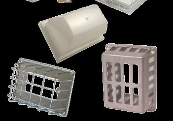
Guards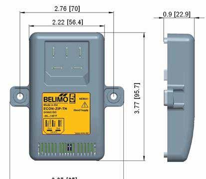
THERMOSTATS & CONTROLLERS
Products manufactured MODEL/SERIES PAGE
in the United States
Accessories
Testing Devices and Tools — Thermostat Tools and Change-Over Thermostats. . . . . . . 1390
Products that are Sensor Mounting Accessories — Thermostat Remote Sensor Accessories. . . . . . . . . . . 1391
new to the catalog Thermostat Guards — Thermostat Guards. . . . . . . . . . . . . . . . . . . . . . . . . . . . . . . . . . . . . 1393
Bulb/Aqua Stats
A19, A28, A319, A419 Series — Bulb Thermostats. . . . . . . . . . . . . . . . . . . . . . . . . . . . . . . 1378
Communicating Thermostats
Prestige IAQ — Programmable/Wireless Thermostats . . . . . . . . . . . . . . . . . . . . . . . . . . . . 1305
VT7200, VT7300 Communicating — Zone and FCU Communicating Thermostats (BACnet,
LON, N2) . . . . . . . . . . . . . . . . . . . . . . . . . . . . . . . . . . . . . . . . . . . . . . . . . . . . . . . . . . . . 1321
VT7600 Communicating — AHU Communicating Thermostat Single and Multistage,
Programmable and Non-programmable (BACnet, LON, N2). . . . . . . . . . . . . . . . . . . . . 1312
T7350, W7350 Series — T7350 Series Programmable Commercial Thermostats and W7350
Controller. . . . . . . . . . . . . . . . . . . . . . . . . . . . . . . . . . . . . . . . . . . . . . . . . . . . . . . . . . . . 1315
Fan Coil Thermostats
VT7200, VT7300 Series — Zone Thermostats and FCU Thermostats. . . . . . . . . . . . . . . . . 1310
TB7100A100 MultiPro™ Series — MultiPro™ Multispeed and Multipurpose
A19/A28/ | p. 1378 Thermostats. . . . . . . . . . . . . . . . . . . . . . . . . . . . . . . . . . . . . . . . . . . . . . . . . . . . . . . . . . 1332
A319/A419 TB6575, TB8575 SuitePro™ Series — Digital Fan Coil Thermostats. . . . . . . . . . . . . . . . . 1346
T158, T168 Series — Floating and Proportional Thermostats. . . . . . . . . . . . . . . . . . . . . . . 1370
T170 Series — Fan Coil Thermostat with ADA-Compliant Digital Display . . . . . . . . . . . . . . 1372
T180 Series — Programmable Fan Coil Thermostats . . . . . . . . . . . . . . . . . . . . . . . . . . . . . 1374
T155, T167 Series — Line and Low Voltage Two-Position and Proportional Thermostats . 1376
Low/High Limit Thermostats
A11 Series — Low Temperature Limit Controls . . . . . . . . . . . . . . . . . . . . . . . . . . . . . . . . . . 1380
A70 Series — Low & High Temperature Limit Controls . . . . . . . . . . . . . . . . . . . . . . . . . . . . 1381
L480 Series — Low Limit Temperature Controls . . . . . . . . . . . . . . . . . . . . . . . . . . . . . . . . . 1382
TSA, TF142 — Low-Limit Temperature Controls. . . . . . . . . . . . . . . . . . . . . . . . . . . . . . . . . . 1384
& CONTROLLERS
TC-105, TC-100 — Duct High Temperature Limits . . . . . . . . . . . . . . . . . . . . . . . . . . . . . . . .
T H E R M O S TAT S
1385
Mechanical Thermostats
T170 Series | p. 1372 ET Series, UT8001 — Two-Position Room Thermostats . . . . . . . . . . . . . . . . . . . . . . . . . . . 1367
T22, T25, T26, T46 — Line-Voltage Thermostats. . . . . . . . . . . . . . . . . . . . . . . . . . . . . . . . . 1368
TF115, TH109, and TRF115 Series — NEMA 4X Industiral Controls Thermostats . . . . . . . 1386
T631F/G, TW155/255 Series — NEMA 4X Rated Thermostats. . . . . . . . . . . . . . . . . . . . . . 1388
TC-1100 Series — Two Position Room Thermostats . . . . . . . . . . . . . . . . . . . . . . . . . . . . . . 1389
Programmable/Non-Programmable Thermostats
1F95, 1F95EZ and 1F97 Series Thermostats — Big Blue™ and Blue™ Universal and Single
Stage Programmable/Non-programmable Thermostats . . . . . . . . . . . . . . . . . . . . . . . . 1323
VT7600 Series — Single and Multistage Programmable and
Non-programmable Thermostats. . . . . . . . . . . . . . . . . . . . . . . . . . . . . . . . . . . . . . . . . . 1327
T87, TH3000, and TH4000 Series — Residential Thermostats, Programmable and Non-
programmable . . . . . . . . . . . . . . . . . . . . . . . . . . . . . . . . . . . . . . . . . . . . . . . . . . . . . . . . 1330
TH5000, TH6000, TB7000 Series — FocusPro™ Residential and Light Commercial
Zip Economizer | Thermostats. . . . . . . . . . . . . . . . . . . . . . . . . . . . . . . . . . . . . . . . . . . . . . . . . . . . . . . . . . 1334
p. 1354 TH8000 Series, TB8220 Series — VisionPro™ Programmable Thermostats. . . . . . . . . . . 1336
1F80 Series — Residential and Light Commercial Thermostats . . . . . . . . . . . . . . . . . . . . . 1338
T4000, T8000, and T12000 Series Thermostats — Digital Display
Programmable Thermostats. . . . . . . . . . . . . . . . . . . . . . . . . . . . . . . . . . . . . . . . . . . . . . 1342
1F72, 1E78 and 1F78 Series Thermostats — Residential LCD Display Programmable/Non-
Programmable Thermostats. . . . . . . . . . . . . . . . . . . . . . . . . . . . . . . . . . . . . . . . . . . . . . 1344
Proportional Room Thermostats (No Fan Control)
TB6980 and TB7980 Series — Floating and Proportional Zone Thermostats. . . . . . . . . . . 1348
RTC-2P — Proportional Room Thermostats . . . . . . . . . . . . . . . . . . . . . . . . . . . . . . . . . . . . 1365
Stand Alone Controllers and Temperature Switches
T775 Series — Single or Multi-Loop Standalone Controller. . . . . . . . . . . . . . . . . . . . . . . . . 1350
System 450 — System 450 Modular Controls . . . . . . . . . . . . . . . . . . . . . . . . . . . . . . . . . . . 1352
ZIP Economizer Series — Economizer. . . . . . . . . . . . . . . . . . . . . . . . . . . . . . . . . . . . . . . . 1354
PXR4 — Setpoint Controllers . . . . . . . . . . . . . . . . . . . . . . . . . . . . . . . . . . . . . . . . . . . . . . . . 1359
kele.com R820 Series — SCR Power Controller. . . . . . . . . . . . . . . . . . . . . . . . . . . . . . . . . . . . . . . . . 1361
UCM-420A — Setpoint Controllers. . . . . . . . . . . . . . . . . . . . . . . . . . . . . . . . . . . . . . . . . . . . 1363
NEW!
                    THERMOSTATS & CONTROLLERS
                                                         PROGRAMMABLE/WIRELESS THERMOSTAT
                                                                               PRESTIGE IAQ

DESCRIPTION
The Prestige High Definition (HD) Color Touchscreen
Thermostat provides control of 24 VAC of heating and
cooling systems. RedLINK™ enabled to work with compatible
wireless accessories. These newly updated thermostats come
in a variety of colors and can be accessed via the internet or
through the mobile app available from Honeywell. The new
Prestige is on the leading edge of design and remote access
when it comes to thermostats for both residential and light
commercial applications. Check out the entire line for one that
fits your application.

FEATURES
• 60% smaller than Prestige 2.0 and available in 4 colors
• Delta T Alerts and Diagnostics inform customers when
  their system is not operating as expected
• Residential or light commercial use
• User Interaction Log provides a searchable history of
  setting changes                                                                       Prestige IAQ-EIM
• Assignable outputs for indoor air quality and staging
  control
• Selectable staging options
• Customizable service reminders
• Up to 4H/2C heat pump or 3H/2C conventional systems

                                                                                                                             THERMOSTATS & CONTROLLERS
 SPECIFICATIONS
Suppy Voltage             24 VAC                                   Temperature Setting Range
System Type               4 heat/2 cool heat pump and up to          Heating             40° to 90°F (4.5° to 32°C)
                          3 heat/2 cool conventional                 Cooling             50° to 99°F (10° to 37°C)
Sensor Type                                                        Operating Temperature
  Temperature             Onboard 20kΩ NTC                           Thermostat          32° to 120°F (0° to 48.9°C)
  Humidity                Capacitive                                 EIM                 -40° to 165°F (-40° to 73.8°C)
Communication             RedLINK devices                          Operating Humidity
Baud Rate                 900 MHz frequency range                    Thermostat          5% to 90% condensing,
Analog Input              EIM                                        EIM                 5% to 95% non-condensing
                          2 Universal inputs, temperature or       Dimensions
                          dry contact selectable (not available      Thermostat
                          with single- piece thermostat)             Prestige IAQ        4-1/2"W x 3-1/2"H x 7/8"D
Output                                                                                   (11.5 x 8.9 x 2.2 cm)
  EIM                   7                                            Prestige 2.0        6-13/16"W x 3-7/8"H x 1-7/16"D
  Standalone            6 (USB on some models)                                           (17.3 x 9.9 x 3.6 cm)
Contact Rating                                                       EIM                 9.34"H X 4.83"W X 1.6"D             21
  EIM terminals W-O/B, Y, W3-Aux2, A-L/A                                                 (23.7 x 12.3 x 4.1 cm)
                        Maximum Current 1.0A,                      Measurement Range     Building material and content
  EIM terminals G, U1, U2, U3                                                            dependent
                        Maximum Current 0.5A                       Weight                2.0 lb (maximum item)
  EIM terminals W2-Aux1, Y2                                        Approvals             This device complies with Part 15
                        Maximum Current 0.6A                                             of the FCC Rules. (15.19, 15.21,
Temperature Sensor Accuracy                                                              15.105)
                        ± 1.5° at 70°F (0.75° at 21°C)             RoHS Statement        Yes
                                                                   Warranty              5 years (excludes batteries)

                                                                                                                      1305
March 2014                                                        WE MAKE IT EASY.      kele.com   888-397-5353 USA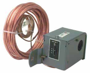
NEW!
THERMOSTATS & CONTROLLERS
PROGRAMMABLE/WIRELESS THERMOSTAT
PRESTIGE IAQ
WIRING - THX9321& THX9421
Typical wiring of a 3-heat / 2-cool heat pump system with one Typical wiring of a 3-heat / 2-cool heat pump system with two
transformer. transformers.
Transformer 120 24 C Air Handler 120 24 C
VAC VAC Transformer VAC VAC
R R
O/B
Thermostat
O/B CHANGEOVER VALVE C
Thermostat
CHANGEOVER VALVE C
AUX/E BACKUP HEAT Rc AUX/E Rc
1 3
Y COMPRESSOR STAGE 1 R Y COMPRESSOR STAGE 1 R
Y2 COMPRESSOR STAGE 2 U1 Y2 COMPRESSOR STAGE 2 U1
G FAN RELAY U1 G FAN RELAY U1
1 1
L/A COMPRESSOR MONITOR U2 L/A COMPRESSOR MONITOR U2
OR ZONE PANEL OR ZONE PANEL
K 2 U2 K 2 U2
6 6
Backup Heat BACKUP HEAT
120 24 R
Transformer VAC VAC
Prestige THX9321 and heat pump system with C
one transformer
Prestige THX9321 and heat pump system with
two transformers
Typical wiring of a 2-heat / 2-cool conventional system with one
transformer.
Transformer
Typical wiring for geothermal radiant heat, geothermal
120 24 C
VAC VAC R forced-air and backup heat with one transformer.
W Transformer
Thermostat
HEAT STAGE 1 C 120 24 C
THERMOSTATS & CONTROLLERS
VAC VAC R
W2 HEAT STAGE 2 Rc
Y COMPRESSOR STAGE 1 O/B
Thermostat
R CHANGEOVER VALVE C
5
Y2 COMPRESSOR STAGE 2 U1 AUX/E BACKUP HEAT Rc
G FAN RELAY U1 Y COMPRESSOR STAGE 1 R
1
A U2 Y2
4
COMPRESSOR STAGE 2 U1
GEOTHERMAL
K U2 G FAN RELAY RADIANT U1
6 HEAT
L/A COMPRESSOR MONITOR STAGE 1 U2
OR ZONE PANEL
K 2 3 U2
Prestige THX9321 and 2-heat / 2-cool 6
conventional system with one transformer
Prestige THX9321 and geothermal radiant heat,
geothermal forced-air and backup heat with one
transformer
1 U1 and U2 terminals are dry contacts.
2 L/A terminal sends continuous output when thermostat is set to EM HEAT mode except when set up for Economizer or TOD.
21 See “Economizer Module Wiring Diagrams” beginning on page 151.
3 U1 or U2 terminals must be used for geothermal radiant heat (ISU 2010). Thermostat allows 2 stages of radiant heat—geothermal
(stage 1) and boiler (stage 2).
4 “U” terminals are normally open dry contacts when set up for geothermal radiant heat. You must install a field jumper if radiant
heat is powered by system transformer. Do NOT install a field jumper if radiant heat has its own transformer.
5 Remove jumper if using separate transformers.
6 Connect the THP9045 Wiresaver Module to the K terminal in heating/cooling applications that do not have a common wire at the
thermostat. The K terminal cannot be used in heat-only applications. See THP9045 installation instructions for more information.
NOTE: For additional set-up, wiring, and operation, see installation manual.
1306 888-397-5353 USA kele.com WHEN YOU NEED IT RIGHT, RIGHT NOW, CALL KELE. March 2014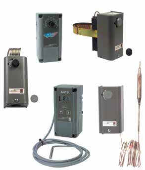
NEW!
THERMOSTATS & CONTROLLERS
PROGRAMMABLE/WIRELESS THERMOSTAT
PRESTIGE IAQ
WIRING - EIM
Typical wiring of a heat pump system with up to Typical wiring of a conventional system with up to
4-stage heat and 2-stage cool with one transformer 3-stage heat and 2-stage cool with one transformer
FURNACE
EIM TO THERMOSTAT
EIM TO THERMOSTAT
R
TRANSFORMER
24 120
C VAC VAC
O/B
CHANGEOVER VALVE
HEAT PUMP
BACKUP HEAT CONV HEAT STAGE 1
POWER O/B STAGE 1 W
AUX1 POWER
HEAT AUX1 W2 HEAT STAGE 2
AUX2 BACKUP HEAT HEAT
COOL AUX2 W3
STAGE 2 COOL HEAT STAGE 3
STATUS FAN
LEDS STATUS FAN
U1 Y COMPRESSOR LEDs
STAGE 1 U1
U2 G
U2 FAN
U3 L/A Y2 COMPRESSOR U3
STAGE 2 A 4
3 G
FAN RELAY Y COMPRESSOR
L/A STAGE 1
COMPRESSOR
3 MONITOR OR Y2 COMPRESSOR
ZONE PANEL STAGE 2
1
JUMPERS 1
A AIR HANDLER A JUMPERS 3
B TRANSFORMER B
4 C
R
24 120 5 C
C VAC VAC D
D
S4 S4
CONNECT CONNECT
CONNECT OPTIONAL S4 CONNECT OPTIONAL S4
SENSORS TO SENSORS TO OPTIONAL SENSORS SENSORS OPTIONAL SENSORS
SENSORS
S3 AND S4 TERMINALS S3 S1 AND S2 TERMINALS TO S3 AND S4 S3 TO S1 AND S2
TERMINALS S3 TERMINALS
S3
2 2 2 2
THERMOSTATS & CONTROLLERS
See installation instructions for additional wiring options.
NOTES
The RedLINK Internet Gateway requires a physical Ethernet connection to an open port on a user-supplied router. The router
must be connected to the internet via a user's Internet Provider for access to the Honeywell server. There is no need for a static
IP address. To date, there have been no reported issues with port blocking or firewalls preventing access.
In order to guard against possible wireless signal overload, assure that all wireless RedLINK devices including the RedLINK
Internet Gateway are spaced a minimum of 2 feet apart from each other for proper operation.
REDLINK WIRELESS GATEWAY (THM6000R1002) CONTRACTOR SETUP
21
1. Connect power to the RedLINK Internet Gateway using the supplied 120VAC power supply wall module.
2. Connect the supplied Ethernet cable from the RedLINK Internet Gateway to an available port on a designated Router (router
supplied by others).
3. Using the Prestige Thermostat Contractor Installation Options Menu select Wireless Device Manager, then select Add Device.
4. Press and release the Connect button located on the bottom of the RedLINK Internet Gateway. The device will appear on the
Thermostat. Exit the menu.
5. Note the Device MAC ID and Device CRC information on the bottom of the device (required for account assignment).
1307
March 2014 WE MAKE IT EASY. kele.com 888-397-5353 USA
NEW!
                                       THERMOSTATS & CONTROLLERS
                                       PROGRAMMABLE/WIRELESS THERMOSTAT
                                       PRESTIGE IAQ

                            GATEWAY SETUP

                                                                                                                              Connect power cord to
                                                Connect RedLINK Gateway to a                                                  an electrical outlet not
                                                router or modem with Ethernet                                                 controlled by a wall switch
                                                cable (RJ45).                             Supplied by Others

                              THM6000R1002
THERMOSTATS & CONTROLLERS

                            ACCOUNT SETUP
                            1.	 Visit www.mytotalconnectcomfort.com and click “Create an Account.” There is no charge for this service.
                            2.	 Enter required account information including email, password and security questions/answers.
                            3.	Account verification email will be sent to account email - log into email and validate account to return to
                                www.mytotalconnectcomfort.com
                            4.	 Enter New Location for RedLINK Internet Gateway including location type (commercial or residential) and alert email accounts
                            5.	Assign RedLINK Internet Gateway to location by entering the unique device MAC ID and device CRC information (Found on
                                bottom of THM6000R1002)

                            Account is now active and may be accessed via any supported web browser or smart phone application.

21

               1308                       888-397-5353 USA   kele.com   WHEN YOU NEED IT RIGHT, RIGHT NOW, CALL KELE.                                   March 2014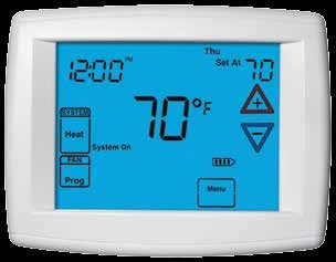
NEW!
                     THERMOSTATS & CONTROLLERS
                                                        PROGRAMMABLE/WIRELESS THERMOSTAT
                                                                              PRESTIGE IAQ

                                                 ORDERING INFORMATION

       PRESTIGE KITS
                        Kit                                                 Included in Kit
                   Part Number                                Part Number                           Description
        Prestige IAQ Kit                       THX9421R5021WW                       Thermostat - White Front, White Side
        YTHX9421R5101WW
                                               THM5421R1021                         Equipment Interface Module
                                               C7089R1013                           Wireless Outdoor Sensor
                                               50062329-001                         Discharge/Return Sensors (Qty. 2)
        Prestige IAQ Kit                       THX9421R5021BB                       Thermostat - Black Front, Black Side
        YTHX9421R5101BB
                                               THM5421R1021                         Equipment Interface Module
                                               C7089R1013                           Wireless Outdoor Sensor
                                               50062329-001                         Discharge/Return Sensors (Qty. 2)
        Prestige IAQ Kit                       THX9421R5021SG                       Thermostat - Silver Front, Gray Side
        YTHX9421R5101SG
                                               THM5421R1021                         Equipment Interface Module
                                               C7089R1013                           Wireless Outdoor Sensor
                                               50062329-001                         Discharge/Return Sensors (Qty. 2)
        Prestige IAQ Kit                       THX9421R5021WG                       Thermostat - White Front, Gray Side
        YTHX9421R5101WG
                                               THM5421R1021                         Equipment Interface Module
                                               C7089R1013                           Wireless Outdoor Sensor
                                               50062329-001                         Discharge/Return Sensors (Qty. 2)

                                                                                                                              THERMOSTATS & CONTROLLERS
        Prestige IAQ Kit                       THX9421R5021WW                       Thermostat - White Front, White Side
        YTHX9421R5085WW
                                               THM5421R1021                         Equipment Interface Module
                                               50062329-001                         Discharge/Return Sensors (Qty. 2)
        Prestige IAQ Kit                       THX9421R5021BB                       Thermostat - Black Front, Black Side
        YTHX9421R5085BB
                                               THM5421R1021                         Equipment Interface Module
                                               50062329-001                         Discharge/Return Sensors (Qty. 2)
        Prestige IAQ Kit                       THX9421R5021SG                       Thermostat - Silver Front, Gray Side
        YTHX9421R5085SG
                                               THM5421R1021                         Equipment Interface Module
                                               50062329-001                         Discharge/Return Sensors (Qty. 2)
        Prestige IAQ Kit                       THX9421R5021WG                       Thermostat - White Front, Gray Side
        YTHX9421R5085WG
                                               THM5421R1021                         Equipment Interface Module
                                               50062329-001                         Discharge/Return Sensors (Qty. 2)
        Prestige 2.0 Kit                       THX9321R5030                         Thermostat
        YTHX9321R5061
                                               REM5000R1001                         Portable Comfort Control                  21
        Prestige 2.0 Kit                       THX9321R5030                         Thermostat
        YTHX9321R5079
                                               C7089R1013                           Wireless Outdoor Sensor
        Note: Part numbers can be ordered separately.

                                                                                                                           1309
March 2014                                                       WE MAKE IT EASY.     kele.com       888-397-5353 USA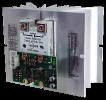
NEW!
                                         THERMOSTATS & CONTROLLERS
                                         ZONE AND FCU COMMUNICATING THERMOSTAT (BACNET, LON)
                                         VT7200, VT7300 COMMUNICATING

                            DESCRIPTION
                            VT7200 Zone thermostats are digital-display, heating/cooling,
                            with outputs for two-position, floating, and proportional terminal
                            unit control. They are ideal for baseboard heat, unit heaters,
                            radiant panels, reheat, or VAV box (pressure-dependent)
                            control. VT7300 Fan Coil Unit (FCU) thermostats are digital-
                            display, heating / cooling, with outputs for two-position, floating,
                            or proportional control. In addition, they include multi-speed
                            fan relays for high, medium, and low fan speed control. Both
                            thermostats offer remote temperature sensor and remote digital
                            inputs configured for night setback, filter alarm, motion sensor,          VT7200C5031B           VT7305C5031B
                            door/window switch, or service indication. All models offer                 BACnet Zone            BACnet FCU
                            standard BACnet or LON open-protocol communications.                         Thermostat            Thermostat
                            FEATURES
                            • BACnet or LON communication                     • Setpoint range limits (heating and       • Heat, cool, and reheat time base
                              models                                            cooling)                                   outputs are configurable
                            • Stand-alone operation on                        • Three configurable inputs for night      • Direct or reverse acting (proportional
                              communication loss                                setback, setback override, motion          models)
                            • Two-position, floating, or proportional           sensor, door or window switch, filter    • Keypad lockout functions
                              models                                            alarm, service advisory, heat/cool       • Dehumidification control models
                            • Remote room sensor option                         changeover °F/°C (configurable)          • Three-speed fan control (FCU model)
                            • Adjustable deadband                             • Display offset                           • Selectable system control (FCU
                            • Single setpoint adjustment                      • Adjustable temporary occupied time         model)
                                                                                                                         • PIR cover sensor (Optional)

                            SPECIFICATIONS
                            Supply Voltage        19-30 VAC, 50/60 Hz                               Universal Input         Dry contact or 10K Type 2 Model 24
                            Supply VA             2 VA                                                                      thermistor
                            Display               Two line backlit LCD, ±0.2°F (±0.1°C)             Remote Sensor           Thermistor, 10K Type 2 Model 24
THERMOSTATS & CONTROLLERS

                            Control Accuracy      Temperature, ±0.9°F (±0.5°C)                      Control Type            Proportional plus integral (PI)
                              VT7350C50xx, VT7350F50x                                               Proportional Band       Heating and cooling, 2°F (1.1°C)
                                                  Dehumidification, ±5% RH from 20% to              Floating Time Base      Adjustable, 0.5 to 9 minutes
                                                  80% RH                                            Cycles Per Hour         Adjustable 3 to 8
                            Thermostat Type       Zone (VT7200) or FCU (VT7300)                     Override Timer          0 to 24 hours, 1-hour increments,
                            Cover Controls                                                                                  pushbutton reset
                              Zone Models         Up/down/override buttons                          Sensor Offset           Adjustable ±5°F (±2.5°C), ±15% RH
                                                  Heat/Cool “on" LEDs                                                       (humidity models)
                              FCU Models          Up/down/°C-or-°F/fan/mode buttons                 Deadband                Adjustable 2° to 5°F (1° to 2.5°C)
                                                  Fan/Heat/Cool “on" LEDs                           Setpoint                Adjusted depending on heating or
                            Control Outputs       See terminal designation table                                            cooling mode, heating and cooling
                              VT7200C50xx         5 triacs (H/C, 2-position or floating                                     setpoints are changed simultaneously
                                                  control)                                                                  with respect to the deadband
                                                                                                      Cooling limits        54° to 100°F (12°C to 37.7°C)
                              VT7200F50xx         1 triac, 2 analog outputs (H/C                      Heating limits        40° to 90°F (4.5° to 32°C)
                                                  proportional 0 to 10 VDC)                         Keypad Lockout          Selectable system/fan/unoccupied
                              VT7300C50xx, VT7350C50xx                                              System Setting          O=off, H=heating, C=cooling,
                                                  3 relays (fan), 5 triacs (H/C, 2-position                                 A=automatic changeover
                                                  or floating control)                                (FCU models)          O/C, O/H, O/A/H/C, H/O/C
                              VT7300F50xx, VT7350F50xx                                              Fan Setting             L=low, M=medium, H=high, A=auto
                                                  3 relays (fan), 1 triac, 2 analog outputs           (FCU models)          L/M/H, L/H, L/M/H/A, L/H/A, On/A
21                                                (H/C proportional 0 to 10 VDC)                    Wiring                  18 AWG maximum, 22 AWG
                              Triacs and relays   30 VAC, 1A, 3A inrush                                                     recommended
                              Analog outputs      0-10 VDC, 2KΩ minimum impedance,                  Enclosure               UL FR1, flame retardant plastic
                                                  direct or reverse acting                          Color                   White
                            Auxiliary Inputs      2 digital inputs, 1 universal input, 1            Mounting                Standard vertical, 2" x 4" box
                                                  remote sensor                                     Operating Temperature   32° to 122°F (0° to 50°C)
                              Configurable as     Service/status reminders                          Operating Humidity      0 to 95% RH (non-condensing)
                                                  Door/window/motion sensor switch                  Dimensions              4.94"H x 3.38"W x 1.13"D
                                                  Filter alarm                                                              (12.5 x 8.6 x 2.9 cm)
                                                  Central night setback clock                       Weight                  0.75 lb (0.34 kg)
                                                  Remote occupied override switch                   Approvals               UL Listed File #E234137, cULus, CE,
                                                  Heat/Cool changeover, contact or                                          LonMark
                                                  sensor                                            RoHS Statement          Yes
                            Digital Inputs        Dry contact                                       Warranty                1 year

               1310                          888-397-5353 USA   kele.com       WHEN YOU NEED IT RIGHT, RIGHT NOW, CALL KELE.                               March 2014
NEW!
THERMOSTATS & CONTROLLERS
ZONE AND FCU COMMUNICATING THERMOSTAT (BACNET, LON)
VT7200, VT7300 COMMUNICATING
WIRING
TABLE 1. TERMINAL DESIGNATIONS BY THERMOSTAT (FCU & ZONE)
ZONE THERMOSTATS FAN COIL UNIT (FCU) THERMOSTATS ** Terminals and function are not present on every thermostat
VT7200C-E VT7200F-E VT7300A-E VT7300C-E VT7350C-E VT7300F-E VT7350F-E < LON Thermostat Function**
VT7200C-B VT7200F-B VT7300A-B VT7300C-B VT7350C-B VT7300F-B VT7350F-B < BACnet
2-position/ Proportional 2-position 2 position/ 2 position/ Proportional Proportional/ Terminal**
floating floating floating/RH RH
X X X X X 1 High speed fan (FCU)
X X X X X 2 Medium speed fan (FCU)
X X X X X 3 Low speed fan (FCU)
X X X X X X X 4 24 VAC hot power for thermostat, fan and BO-(1,2,3,4) AO-(1,2)
X X X X X X X 5 24 VAC common for thermostat, fan and BO-(1,2,3,4) AO-(1,2)
X X X X X X X 6 BO-5, aux output, configurable (reheat, occupied/un-occupied)
X X X X X X X 7 BO-5, aux output, configurable (reheat, occupied/un-occupied)
X X X X 8 BO-3, open heating
X X X 9 BO-4, close heating
X X X 9 AO-2, heating
X X X 10 BO-1, open cooling
X X X 10 AO-1, cooling
X X X X 11 BO-2, close cooling
X X X X X X X 12 BI-1, configurable (night set back clock, motion detector, window switch)
X X X X X X X 13 RS, remote sensor, 10 KΩ thermistor
X X X X X X X 14 Scom, common for remote sensor, BI-(1,2), and UI-1
X X X X X X X 15 BI-2, configurable (door, filter, service, remote override)
X X X X X X X 16 UI-3, configurable (change over contact or sensor, supply air sensor)
FCU & ZONE SERIES THERMOSTATS Network
Relays card
FCU & ZONE Internal device connection
electronics (TRIAC’s except as noted)
Fan Fan Fan 24 V 24 V B A A B S **
BO-5 BO-5 BO-3 O O O O BO-2 BI-1 RS BI-2 UI-3
H M L HOT COM 4 2 1 1 COM + – Ref
Fan Fan Fan * AUX O H C Prop Prop O C C
H M L H C Type 2
Sensor Type 2 To network
sensor • BACnet
THERMOSTATS & CONTROLLERS
24 VAC 24 VAC
C/O • Lon Talk
2-Pos Proportional 2-Pos Window Remote Door or
or Fltg 0-10 VDC or Fltg D/N clock room filter Supply
motion sensor service air
T-1 T-2 rem. temp.
override
24 VAC Transformer 2-Pos, Fltg, Proportional
(provided by others) depending on model
Note: Terminals are Thermostat Dependent See Table 1. ** Common device reference on BACnet networks as needed.
*One Transformer Wiring (Delete T2)
Alternate Device Based on Set-up
ORDERING INFORMATION
MODEL THERMOSTAT TYPE
VT7200 Zone controller
VT7300 Fancoil controller commercial (override occupancy)
VT7305 Fancoil controller hospitality (hotel/lodging with temp scale)
VT7350 Fancoil controller commercial (override occupancy) with humidity sensor
VT7355 Fancoil controller hospitality (hotel/lodging with temp scale) with humidity sensor
OUTPUTS
C 2 floating + 1 digital (for VT7200), 2 floating + 1 auxiliary (for VT73xx)
F 2 analog + 1 digital (for VT7200), 2 analog + 1 auxiliary (for VT73xx)
COVER
5000 Viconics logo
5031 Blank cover (no logo)
5500 PIR cover with Viconics logo
5531 PIR cover blank (no logo)
21
COMMUNICATION PROTOCOL
E Echelon/LONworks
B BACnet
P Wireless/Zigbee Pro
W Wireless
VT7305 C 5031 W Example: VT7305C5031W Hospitality fancoil controller with
2 floating + 1 auxiliary outputs in a blank cover case
with wireless communication protocol
ACCESSORIES PAGE
COV-PIR-FCU-C-5031 PIR cover for FCU thermostat
COV-PIR-ZN-5031 PIR cover for Zone thermostat
TG511A1000 Thermostat guard- clear-medium size 1392
1311
March 2014 WE MAKE IT EASY. kele.com 888-397-5353 USA
NEW!
                                       THERMOSTATS & CONTROLLERS
                                       AHU COMMUNICATING THERMOSTAT SINGLE AND MULTISTAGE,
                                       PROGRAMMABLE AND NON-PROGRAMMABLE, (BACNET, LON)
                                       VT7600 COMMUNICATING
                            DESCRIPTION
                            The VT7600 Communicating Thermostats are digital
                            display, single or multistage, seven-day programmable or
                            nonprogrammable PI thermostats (°F or °C) for use with
                            AHU controls and heat pumps for both heating and cooling                                  VT7600A5031B
                            applications. The VT7600 has both system and fan switching                               BACnet Thermostat
                            with internal sensor or remote sensor capabilities. Five
                            buttons control a simplified menu for over 20 configurable
                            parameters. A communication card is added for multiple
                            protocols, including BACnet and LON. Other control features
                            are listed below.

                            FEATURES                                    •   PIR cover available                     PROGRAMMABLE MODELS
                            ALL MODELS                                  •   Permanent program retention             • Two or four configurable events per
                            • No logo on thermostat cover               •   Two configurable DI inputs                day
                            • 1H/1C, 2H/2C (3H/2C heat pump)            •   Two line LCD display (°F or °C)         • Progressive recovery or none
                              models                                    •   Proportional + Integral control         • 12 or 24 hour clock
                            • Fan switching (on/auto/smart)                                                         • Six hour clock retention
                            • System switching (O/A/C/H)                ECONOMIZER MODELS                           • Occ/Unocc auxiliary contact out
                            • Two line 8 digit backlit LCD Display      • Mixed-air (0-10V) control outputs
                            • Three status LEDs (Fan, Clg, Htg)         • Mixed-air sensor input                    COMMUNICATION MODELS
                            • Five control keys                         • Mixed-air setpoint (SP)                   • BACnet
                            • Remote sensor and OSA sensor              • Economizer changeover S.P.                • LON
                              inputs                                      temperature                               • Wireless
                            • Adjustable deadband                       • OSA damper minimum position in %          • Wireless/ Zigbee Pro

                            SPECIFICATIONS
                            Supply Voltage            20-30 VAC, 50/60 Hz                     Control Output           1A relays 30 VAC, 3A surge maximum
                            Supply VA                 2 VA                                    Auxillary Contact Output 1A relay 30 VAC, N.O./N.C. follows
THERMOSTATS & CONTROLLERS

                            Display                   Two-line backlit LCD                                             occupied schedule
                            Controls                  Five menu-driven push buttons – up,     Mixed Air Output         Proportional 0-10V DC, 2 kΩ minimum
                                                      down, menu, no, yes/scroll                                       (economizer model)
                            Thermostat Type           Seven-day programmable models, non-     Control Type             Proportional plus integral
                                                      programmable models                     Deadband                 Adjustable 2° to 4°F (1° to 2°C)
                            Optimal Start             Progressive recovery (enable/disable)   OSA Lockout Limits
                            Heat Pump High/Low        OSA lockout (emer heating/comp.           Heating                15° to 120°F (26° to 49°C), 5°F
                                                      heating)                                                         increments
                            Stages                    (Dependent upon model) 1H/1C,             Cooling                -40° to 95°F (-40° to 35°C), 5°F
                                                      2H/2C, (3H/2C heat pump) 2H/2C +                                 increments
                                                      proportional mixed-air economizer       Low Limit Protection     Enable/disable, heating @ 47°F (5.5°C)
                            Memory (schedule)         Permanent EEPROM                        Power Up Delay           10 to 120 seconds
                            Clock (12 or 24 hour)     Six-hour power fail retention           Keypad Lockout           Three levels (full, none, partial)
                            System Switching          Off/Auto/Cool/Heat                      Cycles Per Hour          Adjustable, heating 3-8 CPH, cooling
                            Fan Switching             On-continuous                                                    3-4 CPH
                                                      Auto-on demand                          Display Offset           Adjustable ±5°F (2.5°C), 1°F
                                                      Smart-on/occupied, off/unoccupied                                increments
                            Control Accuracy          ±0.9°F (±0.5°C) @ 70°F (21°C)           LED Indicators           Three green on (fan, cooling, heating)
                            Setpoint Range                                                    Wiring                   18 AWG max, 22 AWG recommended
                              Heating                40° to 90°F (4.5° to 32°C)               Operating Temperature 32° to 122°F (0° to 50°C)
                              Cooling                54° to 100°F (12° to 37.5°C)             Operating Humidity       0% to 95% RH (non-condensing)
21                          Setpoint High/Low Limits Individually adjustable, H/C             Enclosure                ULFR1 flame-retardant plastic
                            Remote Sensor                                                     Color                    White
                              Room Sensor            Room sensor input auto-detected 10K      Mounting                 Standard vertical 2" x 4" box
                                                     Type 2 thermistors                       Dimensions               4.94"H x 3.38"W x 1.13"D
                              Outside Air            Outside air input auto-detected 10K                               (12.5 x 8.6 x 2.9 cm)
                                                     Type 2 thermistors                       Weight                   0.75 lb (0.34 kg)
                              Mixed Air              Mixed air input auto-detected            Approvals                UL Listed File #E234137, cUL, CE,
                                                     (economizer model only) 10K Type 2                                LonMark
                                                     thermistors                              RoHS Statement           Yes
                            Auxiliary Inputs         Two dry contact digital inputs           Warranty                 1 year
                              Four Types             Service/status reminders
                                                     Filter alarm
                                                     Central night setback clock
                                                     Remote occupied override timer

               1312                       888-397-5353 USA   kele.com    WHEN YOU NEED IT RIGHT, RIGHT NOW, CALL KELE.                                March 2014
NEW!
THERMOSTATS & CONTROLLERS
AHU COMMUNICATING THERMOSTAT SINGLE AND MULTISTAGE,
PROGRAMMABLE AND NON-PROGRAMMABLE, (BACNET, LON)
VT7600 COMMUNICATING
WIRING
TABLE 1. TERMINAL DESIGNATION BY THERMOSTAT MODEL
THERMOSTAT MODEL VT7600 Note: Terminals and functions are not present on every thermostat
VT7600A-E VT7600B-E VT7605B-E VT7600H-E VT7652A-E VT7652B-E VT7656B-E VT7652H-E Function
LON
VT7600A-B VT7600B-B VT7605B-B VT7600H-B VT7652A-B VT7652B-B VT7656B-B VT7652H-B BACNET
Energizes on a call for first stage cooling (first stage heating HP)
Energizes on a call for second stage cooling (second stage heating HP)
Energizes fan in accordance with the selected fan mode
24 VAC from equipment transformer
24 VAC (common) from equipment transformer
RH24 VAC for heating stages (jumper to RC for single power systems)
W1Energizes on a call for first stage heating (third stage heating HP)
W2Energizes on a call for second stage heating
O/BHP reversing valve configurable (O = on or B = on)
AUXConfigurable auxiliary output (follows schedule)
D1Configurable digital input
D2Configurable digital input
EC0 - 10 VDC economizer actuator output
RSRemote room sensor
ScomSensor common
OSOutdoor air sensor
MSMixed air sensor
VT7600 SERIES THERMOSTAT Internal relays and connections Network
card
VT Thermistor
electronics sensor inputs
0-10V
Y1 Y2 G RC C **
RH W1 W2 O/B AUX D1 D2 EC RS Scom OS MS
+ – Ref
*
Heat 1 Heat 2 Rev. Aux ACT.
Cool 1 Cool 2 Fan valve
To Network
Type 2 Type 2 Type 2 • BACnet
THERMOSTATS & CONTROLLERS
* • LonTalk
24V 24V
Note: All outputs are
24 VAC. * * If using the same power source for the thermostat and heating loads, delete
transformer T-2 and install a jumper across RC and RH. Then wire W1 and W2
Note: Terminals are T-1 T-2 common to T1 ( ).
thermostat-dependent. 24 VAC Thermostat Power
See Table 1. ** Common device reference on BACnet.
(provided by installer)
21
1313
March 2014 WE MAKE IT EASY. kele.com 888-397-5353 USANEW!
THERMOSTATS & CONTROLLERS
AHU COMMUNICATING THERMOSTAT SINGLE AND MULTISTAGE,
PROGRAMMABLE AND NON-PROGRAMMABLE, (BACNET, LON)
VT7600 COMMUNICATING
ORDERING INFORMATION
MODEL THERMOSTAT TYPE
VT7600 RTU controller, no local schedule
VT7605 RTU + economizer controller, no local schedule
VT7606 RTU + IAQ + economizer controller, no local schedule
VT7607 RTU + humidity controller, no local schedule
VT7652 RTU controller, local schedule
VT7656 RTU + economizer controller, local schedule
VT7657 RTU + humidity controller, local schedule
OUTPUTS
A 1H/1C (VT7600 and VT7652 only)
B 2H/2C (Not available on VT7606)
E 2H/2C + IAQ + economizer controller (VT7606 and VT7656 only)
F 2C + Analog heat controller (VT7600 and VT7652 only)
H 3H/3C Heatpump controller (VT7600 and VT7652 only)
W 2H/2C + humidity +watersource heatpump controller (VT7600 and VT7652 only)
COVER
5000 Viconics logo
5031 Blank cover (no logo)
5500 PIR cover w/ Viconics logo
5531 PIR cover blank (no logo)
COMMUNICATION PROTOCOL
E Echelon/LONworks
B BACnet
P Wireless/Zigbee Pro
W Wireless
VT7605 B 5031 W Example: VT7605B5031W RTU + economizer with 2 heat/2 cool,
blank cover, wireless
ACCESSORIES PAGE
THERMOSTATS & CONTROLLERS
TG511A1000 Thermostat guard- clear-medium size 1392
COV-PIR-HPUMP-5031 PIR cover for HP thermostat
COV-PIR-RTU-5032 PIR cover for RTU thermostat
21
1314 888-397-5353 USA kele.com WHEN YOU NEED IT RIGHT, RIGHT NOW, CALL KELE. March 2014NEW!
THERMOSTATS & CONTROLLERS
T7350 SERIES PROGRAMMABLE COMMERCIAL THERMOSTATS
AND W7350 CONTROLLER
T7350, W7350 SERIES
DESCRIPTION
The T7350 Commercial Programmable Thermostat controls 24
VAC single zone heating, ventilating and air conditioning (HVAC)
equipment. The T7350 consists of a thermostat and a subbase. The
thermostat includes the keypad and display for 7-day programming
and the subbase includes equipment control connections. T7350M
models have 2 modulating outputs for heat and/or cool, and the
T7350H models have LonWorks® capability.
The W7350 WebStat is a web-based building manager that allows
contractors and facility managers to view and command T7350H
Commercial Programmable Thermostats. It communicates over
the LonWorks® network to perform building management control
of the T7350H thermostats through a web browser. It runs building
management applications such as trending, scheduling and alarming. T7350 Series
The WebStat Bundle (W7350A1000) includes the WebStat controller,
a LON® card, and a power supply.
FEATURES
• 7-day programming with two Occupied and two Not Occupied • Remote sensor capability for temperature (including outdoor air
periods per day and discharge air) and humidity sensors
• Individual heat and cool setpoints for Occupied and Not • T7350M provides 2 modulating heat and/or cool outputs
Occupied periods • T7350H provides networking capability on LonWorks® bus
• Advanced configuration using TStatSpec software or PDA using Free Topology Transceiver (FTT)
• PID control minimizes temperature fluctuations • T7350H conforms to LonMark® Space Comfort Profile for
• Recovery ramp control automatically optimizes equipment rooftop applications
start times based on building load • W7530 web-based controller supports up to 20 W7350H
• Keypad multi-level lockout available with all models thermostats
THERMOSTATS & CONTROLLERS
SPECIFICATIONS
T7350 Models All Relay Outputs (at 30 Vac)
Mounting Means Mounts on subbase; subbase mounts Running 1.5A maximum
on wall using two 5/8” long #6-32 screws Inrush 7.5A maximum
(included). Modulating Output 4 to 20 mA with 510 ohm maximum
Throttling Range for Modulating Outputs terminating resistance
Automatically adjusts based on heat/cool System Current Draw (without load)
stages. 5 VA maximum at 30 Vac, 50/60 Hz
Manually adjustable with TStatSpec NOTE: Relays are N.O. Single-Pole, Single-Throw (SPST).
software or PDA Outdoor Sensor Wiring Requires 18 gauge wire
Clock Accuracy (at 77°F [25°C]) Humidity Ratings 5% to 90% RH, noncondensing.
±1 min./month (30 days) Emergency Heat Indication
Minimum Stage Operation Time (fixed) Display indicates when Emergency Heat
Minimum On Heat: 1 minute; cool: 3 minutes is activated (Em)
Minimum Off (Cool and Heat Pump) Temperature Ratings
1 minute Operating Ambient 30° to 110°F (-1° to 43°C)
Power 24 VAC, 50/60 Hz.; 20 to 30 VAC, 50/60 Shipping -30° to +150°F (-34°°C to +66°C)
Hz Display Accuracy ±1°F (±1°C)
Input Setpoint 21
Temperature 20KΩ Range Heating: 40° to 90°F (4° to 32°C)
Humidity 0-10 VDC Cooling 45° to 99°F (7° to 37°C)
Outdoor 3000 PTC Deadband 2°F (1°C)
Discharge Air 20KΩ Loss of Power The thermostat maintains programmed
Occupancy Sensor Dry contact switching 30 VDC at times and temperatures for the life of the
1 mA product. Clock and day information is
retained for a minimum of 48 hours.
NOTE: To achieve the 48-hour power-loss clock retention, the T7350
must be powered for at least 5 minutes.
1315
March 2014 WE MAKE IT EASY. kele.com 888-397-5353 USANEW!
THERMOSTATS & CONTROLLERS
T7350 SERIES PROGRAMMABLE COMMERCIAL THERMOSTATS
AND W7350 CONTROLLER
T7350, W7350 SERIES
SPECIFICATIONS (continued)
Communicating Model T7350H: PDA System Requirements
Connection Terminals for the LonWorks Palm OS® 3.5.x to 5.2.1
Bus. Dynamic Heap 256K bytes
Network jack for quick access by personal Free RAM Space 1000K bytes
computer based tools. Serial Communications RS-232
Communications service-pin pushbutton Approvals European Community Mark (CE) Listed.
to simplify startup. UL 873 Recognized, NEC Class 2.FCC
LonMark Functional Profile Part 15 subpart J Class A.cUL.
8500_20 Space Comfort Controller. Dimensions
LonMark SCC Object Type T7350 models 6-3/4"W x 4-1/2"H x 2-3/16"D
8504 Rooftop See Fig. 2. (17.1 x 11.4 x 5.6 cm)
LonMark Program Identifier W7350 model 6-23/32"W x 4"H x 2-3/16"D
80:00:0C:55:04:03:04:2E. (17.1 x 10.2 x 5.6 cm)
LonMark Application Interoperability Weights
Version 3.3 T7350 models 1.25 lb (0.57 kg)
Honeywell LonMark Plug-In file downloads: W7350 model 1.25 lb (0.57 kg)
plugin.ge51.honeywell.de/index.htm# Warranty 1 year
TStat Spec System Requirements Note: For more specification data on the W7350 please see
Windows XP or Windows 7 manufacturer’s specification sheet. (www.kele.com)
T7350 THERMOSTAT FEATURES
Maximum Stagesa
Auxiliary LONWORKS®
Model Applications Heat Cool Features Relay Capability?
T7350A 1b 1b Yes No
T7350B Conventional or 2b 2b Outdoor, Discharge Air Capability Yes No
Heat Pump
THERMOSTATS & CONTROLLERS
T7350D Yes No
3 (2)c 3 (4)c Humidity, Occupancy, Outdoor, Discharge Air Capability
T7350H1009 Isolated Yes
Normally
T7350H1017 Humidity, Occupancy, Outdoor, Discharge Air Capability, Open Yes
Modulating 2 modulating, 2b relay
4-20 mA output (2-10 VDC with 500 ohm resistor)
T7350M Yes No
a All models are down-selectable and can be configured to control fewer stages than the maximum allowed.
b One extra stage (of either heat or cool) can be configured using the auxiliary relay.
c Heat pump applications for these models have a maximum of two heat stages and two cool stages.
DEFAULT SETPOINTS
Control Occupied Not Occupied Standby
Heating 70°F (21°C) 55°F (13°C) 67°F (19°C)
Cooling 75°F (24°C) 85°F (29°C) 78°F (26°C)
21
1316 888-397-5353 USA kele.com WHEN YOU NEED IT RIGHT, RIGHT NOW, CALL KELE. March 2014NEW!
THERMOSTATS & CONTROLLERS
T7350 SERIES PROGRAMMABLE COMMERCIAL THERMOSTATS
AND W7350 CONTROLLER
T7350, W7350 SERIES
WIRING
SUBBASE
X RH RC AUX W1 Y1 G
2
HEAT FAN
RELAY 1 RELAY
COMPRESSOR
HEAT
CONTACTOR 1
RELAY 2
L2 L2
1 1
L1 L1
(HOT) (HOT)
HEATING COOLING
TRANSFORMER TRANSFORMER
1 POWER SUPPLY. PROVIDE DISCONNECT MEANS AND OVERLOAD PROTECTION AS REQUIRED.
2 WHEN INSTALLED ON A SYSTEM WITH TWO TRANSFORMERS, REMOVE THE FACTORY-INSTALLED JUMPER.
Typical hookup of T7350A in two-stage heat and one-stage cool conventional system with two transformers
TR23 REMOTE SENSOR OUTDOOR
SENSOR
BYPASS
AIR
SET PT
SENSOR COMPRESSOR
GND
THERMOSTATS & CONTROLLERS
LED
CONTACTOR 2
1 2 3 4 5 6 7 8 9 10 11 12 DISCHARGE
AIR HEAT
SENSOR RELAY 2
SUBBASE
T5 T6 T7 T4 T3 OS OS AS AS W2 Y2
X RH RC AUX W1 Y1 G
2
HEAT FAN
RELAY 1 RELAY
COMPRESSOR
CONTACTOR 1
3
L2 ECONOMIZER L2
1 1
L1 L1
(HOT) (HOT)
HEATING COOLING
TRANSFORMER TRANSFORMER
1 POWER SUPPLY. PROVIDE DISCONNECT MEANS AND OVERLOAD PROTECTION AS REQUIRED. 21
2 WHEN INSTALLED ON A SYSTEM WITH TWO TRANSFORMERS, REMOVE THE FACTORY-INSTALLED JUMPER.
3 USE ECONOMIZER INSTRUCTIONS FOR INSTALLATION DIRECTIONS.
Typical hookup of T7350B in two-stage heat and two-stage cool conventional system with two transformers
1317
March 2014 WE MAKE IT EASY. kele.com 888-397-5353 USANEW!
THERMOSTATS & CONTROLLERS
T7350 SERIES PROGRAMMABLE COMMERCIAL THERMOSTATS
AND W7350 CONTROLLER
T7350, W7350 SERIES
WIRING
TR23-H REMOTE SENSOR OUTDOOR 4
BYPASS
SENSOR
AIR
SET PT
COMPRESSOR
SENSOR ECONOMIZER CONTACTOR 2
GND
LED
1 2 3 4 5 6 7 8 9 10 11 12 DISCHARGE HEAT HEAT
AIR RELAY 3 RELAY 2
SENSOR
SUBBASE
T5 T6 T7 T4 T3 OS OS AS AS AUX W3/Y4 Y3 W2 Y2
HS HC HP M M X RH RC AUX W1 Y1 G
COMPRESSOR
CONTACTOR 3
HUMIDITY MOTION 3 HEAT FAN
SENSOR SENSOR RELAY 1 RELAY
COMPRESSOR
L2 CONTACTOR 1
1 2
L1
(HOT)
1 POWER SUPPLY. PROVIDE DISCONNECT MEANS AND OVERLOAD PROTECTION AS REQUIRED.
2 ENSURE TRANSFORMER IS SIZED TO HANDLE THE LOAD.
3 HEAT/COOL SYSTEMS WITH ONE TRANSFORMER REQUIRE THE FACTORY-INSTALLED JUMPER.
4 USE ECONOMIZER INSTRUCTIONS FOR INSTALLATION DIRECTIONS.
5 NO NEED TO WIRE HC TERMINAL BECAUSE THE T3 TERMINAL IS INTERNALLY TIED TO HC, WHICH IS ALSO TIED TO TERMINAL 1 COMMON AT THE SENSOR.
Typical hookup of T7350D in three-stage heat and three-stage cool conventional system with one transformer.
THERMOSTATS & CONTROLLERS
TR23-H REMOTE SENSOR OUTDOOR 4
SENSOR
AIR
BYPASS
COMPRESSOR
SET PT
SENSOR ECONOMIZER CONTACTOR 2
GND
LED
1 2 3 4 5 6 7 8 9 10 11 12 DISCHARGE HEAT HEAT
AIR RELAY 3 RELAY 2
SENSOR
SUBBASE
T5 T6 T7 T4 T3 OS OS AS AS AUX W3/Y4 Y3 W2 Y2
EB EB HS HC HP M M X RH RC AUX W1 Y1 G
5 COMPRESSOR
CONTACTOR 3
LONWORKS® HUMIDITY MOTION 3 HEAT FAN
BUS SENSOR RELAY 1 RELAY
SENSOR
LONWORKS®
BUS
COMPRESSOR
L2 CONTACTOR 1
1 2
21 L1
(HOT)
1 POWER SUPPLY. PROVIDE DISCONNECT MEANS AND OVERLOAD PROTECTION AS REQUIRED.
2 ENSURE TRANSFORMER IS SIZED TO HANDLE THE LOAD.
3 HEAT/COOL SYSTEMS WITH ONE TRANSFORMER REQUIRE THE FACTORY-INSTALLED JUMPER.
4 USE ECONOMIZER INSTRUCTIONS FOR INSTALLATION DIRECTIONS.
5 WHEN USING THE TR23-H FOR HUMIDITY SENSING THERE IS NO NEED TO WIRE HC TERMINAL BECAUSE THE T3 TERMINAL IS INTERNALLY TIED TO HC,
WHICH IS ALSO TIED TO TERMINAL 1 COMMON AT THE SENSOR
Typical hookup of T7350H1009 in three-stage heat and three-stage cool conventional system with one transformer
1318 888-397-5353 USA kele.com WHEN YOU NEED IT RIGHT, RIGHT NOW, CALL KELE. March 2014NEW!
THERMOSTATS & CONTROLLERS
T7350 SERIES PROGRAMMABLE COMMERCIAL THERMOSTATS
AND W7350 CONTROLLER
T7350, W7350 SERIES
WIRING
TR23-H REMOTE SENSOR OUTDOOR MODULATING R
BYPASS
COOL
SENSOR
AIR –
SET PT
SENSOR + (4-20 mA) X
GND
LED
1 2 3 4 5 6 7 8 9 10 11 12 DISCHARGE MODULATING R
AIR – HEAT
SENSOR + (4-20 mA) X
SUBBASE
T5 T6 T7 T4 T3 OS OS AS AS MX MH MC AUX
EB EB HS HC HP M M X RH RC AUX W1 Y1 G
4 2
LONWORKS® HUMIDITY MOTION HEAT FAN
BUS SENSOR SENSOR RELAY 1 RELAY
LONWORKS®
BUS
COMPRESSOR
CONTACTOR 1
3
L2 L2
1 ECONOMIZER 1
L1 L1
(HOT) (HOT)
HEATING COOLING
TRANSFORMER TRANSFORMER
1 POWER SUPPLY. PROVIDE DISCONNECT MEANS AND OVERLOAD PROTECTION AS REQUIRED.
2 WHEN INSTALLED ON A SYSTEM WITH TWO TRANSFORMERS, REMOVE THE FACTORY-INSTALLED JUMPER.
3 USE ECONOMIZER INSTRUCTIONS FOR INSTALLATION DIRECTIONS.
4 WHEN USING THE TR23-H FOR HUMIDITY SENSING THERE IS NO NEED TO WIRE HC TERMINAL BECAUSE THE T3 TERMINAL IS INTERNALLY TIED TO HC, WHICH
IS ALSO TIED TO TERMINAL 1 COMMON AT THE SENSOR.
Typical hookup of T7350H1017 for system with two independent heat stages (one modulating),
THERMOSTATS & CONTROLLERS
two independent cool stages (one modulating), and two transformers.
TR23-H REMOTE SENSOR OUTDOOR MODULATING R
BYPASS
SENSOR
AIR –
SET PT
COOL
5 SENSOR + (4-20 mA) X
GND
LED
1 2 3 4 5 6 7 8 9 10 11 12 DISCHARGE MODULATING R
AIR – HEAT
SENSOR + (4-20 mA) X
SUBBASE
T5 T6 T7 T4 T3 OS OS AS AS MX MH MC
HS HC HP M M X RH RC AUX W1 Y1 G
HUMIDITY MOTION 3 HEAT FAN
SENSOR SENSOR RELAY 1 RELAY
COMPRESSOR
CONTACTOR 1
4
21
L2
1 2
ECONOMIZER
L1
(HOT)
1 POWER SUPPLY. PROVIDE DISCONNECT MEANS AND OVERLOAD PROTECTION AS REQUIRED.
2 ENSURE TRANSFORMER IS SIZED TO HANDLE THE LOAD.
3 HEAT/COOL SYSTEMS WITH ONE TRANSFORMER REQUIRE THE FACTORY-INSTALLED JUMPER.
4 USE ECONOMIZER INSTRUCTIONS FOR INSTALLATION DIRECTIONS.
5 WHEN USING THE TR23-H FOR HUMIDITY SENSING THERE IS NO NEED TO WIRE HC TERMINAL BECAUSE THE T3 TERMINAL IS INTERNALLY TIED TO HC,
WHICH IS ALSO TIED TO TERMINAL 1 COMMON AT THE SENSOR.
Typical hookup of T7350M for system with two independent heat stages (one modulating),
two independent cool stages (one modulating), and one transformer.
1319
March 2014 WE MAKE IT EASY. kele.com 888-397-5353 USANEW!
THERMOSTATS & CONTROLLERS
T7350 SERIES PROGRAMMABLE COMMERCIAL THERMOSTATS
AND W7350 CONTROLLER
T7350, W7350 SERIES
ORDERING INFORMATION
MODEL DESCRIPTION
T7350A1004 Single stage heat pump compatible with auxiliary
T7350M1008 Modulating with 2 stage heat and 2 stage cool
T7350B1002 Multi-stage heat pump compatible with auxiliary
T7350D1008 Multi-stage heat pump compatible with occupancy and humidity feature and auxiliary
T7350H1009 Multi-stage heat pump compatible with occupancy and humidity feature communicating LonWorks®
T7350H1017 Modulating with 2 stage heat and 2 stage cool with occupancy and humidity feature communicating LonWorks®
W7350A1000 Webstat controller for T7350 series thermostats
ACCESSORIES
MODEL DESCRIPTION
50014064-001 Infra-red thermostat module for T7350 Series
C7041B2005 Duct temperature sensor, 6 inch
C7041B2013 Duct temperature sensor, 12 inch
C7041C2003 Duct temperature sensor, 18 inch
C7041J2007 Duct temperature averaging sensor, 12 foot
C7089R2013 Wireless outdoor sensor
THERMOSTATS & CONTROLLERS
21
1320 888-397-5353 USA kele.com WHEN YOU NEED IT RIGHT, RIGHT NOW, CALL KELE. March 2014NEW!
THERMOSTATS & CONTROLLERS
ZONE THERMOSTAT AND FCU THERMOSTAT
VT7200, VT7300 SERIES
DESCRIPTION
VT7200 Zone thermostats are digital-display, heating/cooling,
with outputs for two-position, floating, and proportional
terminal unit control. They are ideal for baseboard heat,
unit heaters, radiant panels, reheat, or VAV box (pressure-
dependent) control. VT7300 Series Fan Coil Unit (FCU)
thermostats are digital-display, heating / cooling, with outputs
for two-position, floating, or proportional control. In addition,
they include multispeed fan relays for high, medium, and low
fan speed control. Both thermostats offer remote temperature
sensor and remote digital inputs configured for night setback, VT7305C50xx
filter alarm, motion sensor, door/window switch, or service VT7200C50xx
FCU Thermostat
indication. Zone Thermostat
FEATURES
• °F/°C (configurable)
• Zone or FCU control models • Display offset
• Two-position, floating, or proportional models • Adjustable temporary occupied time
• Remote room sensor option • Heat, cool, and reheat time base outputs are
• Adjustable deadband configurable
• Setpoint range limits (heating and cooling) • Direct or reverse acting (proportional models)
• Three configurable inputs for any of: night setback, • Keypad lockout functions
setback override, motion sensor, door or window • Dehumidification control models
switch, filter alarm, service advisory, heat/cool • Three-speed fan control (FCU model)
changeover • Selectable system control (FCU model)
SPECIFICATIONS
Supply Voltage 19-30 VAC, 50/60 Hz Control Type Proportional plus integral (PI)
Supply Current 2 VA Proportional Band Heating and cooling, 2°F (1.1°C)
Display Two-line backlit LCD, ±0.2°F (0.1°C) Floating Time Base Adjustable, 0.5 to 9 minutes
Control Accuracy Temperature, ±0.9°F (±0.5°C) Cycles Per Hour Adjustable 3 to 8
THERMOSTATS & CONTROLLERS
VT7355C50xx, VT7355F50xx Override Timer 0 to 24 hours, 1-hour increments,
Dehumidification, ±5% RH from 20 to pushbutton reset
80% Sensor Offset Adjustable ±5°F (±2.5°C), ±15% RH
Thermostat Type Zone (VT7200) or FCU (VT7300) (humidity models)
Cover Controls Deadband Setpoint Adjustable 2° to 5°F (1° to 2.5°C)
Zone Models Up/down/override buttons Heat/Cool Adjusted depending on heating
“on” LEDs or cooling mode, heating and
FCU Models Up/down/°C-or-°F/fan/mode buttons cooling setpoints are changed
Fan/Heat/Cool “on” LEDs simultaneously with respect to the
Control Outputs See terminal designation table deadband
VT7200C50xx 5 triacs (H/C, 2-position or floating) Cooling Limits 54° to 100°F (12° to 37.7°C)
VT7200F50xx 1 triac, 2 analog outputs (H/C Heating Limits 40° to 90°F (4.5° to 32°C)
proportional 0 to 10 VDC) Keypad Lockout Selectable system/fan/unoccupied
VT73(05,55)C50xx 3 relays (fan), 5 triacs (H/C, System Setting O=off, H=heating, C=cooling,
2-position or floating control) A=automatic changeover
VT73(05, 55)F50xx 3 relays (fan), 1 triac, 2 analog FCU Models O/C, O/H, O/A/H/C, H/O/C
outputs (H/C proportional 0 to 10 Fan Setting L=low, M=medium, H=high, A=auto
VDC) FCU Models L/M/H, L/H, L/M/H/A, L/H/A, On/A
Triacs and Relays 30 VAC, 1A, 3A inrush Enclosure UL FR1, flame retardant plastic
Analog Outputs 0-10 VDC, 2K minimum impedance, Mounting Standard vertical, 2" x 4" box
Auxiliary Inputs
direct or reverse acting
2 digital inputs, 1 universal input,
Wiring 18 AWG maximum, 22 AWG
recommended 21
1 remote sensor Color White
Configurable as Service/status reminders Operating Temperature 32° to 122°F (-30° to 50°C)
Door/window/motion sensor switch Operating Humidity 0–95% RH non-condensing
Filter alarm Dimensions 4.94"H x 3.38"W x 1.13"D
Central night setback clock (12.5 x 8.6 x 2.9 cm)
Remote occupied override switch Weight 0.75 lb (0.34 kg)
Heat/Cool changeover, contact or Approvals UL, cUL, File #E234137, CE
sensor RoHS Statement Yes
Digital Inputs Dry contact Warranty 1 year
Universal Input Dry contact or 10K Type 2 Model 24
thermistor
Remote Sensor Thermistor, 10K Type 2 Model 24
1321
March 2014 WE MAKE IT EASY. kele.com 888-397-5353 USANEW!
THERMOSTATS & CONTROLLERS
ZONE THERMOSTAT AND FCU THERMOSTAT
VT7200, VT7300 SERIES
WIRING
TABLE 1. TERMINAL DESIGNATIONS BY THERMOSTAT MODEL
ZONE THERMOSTATS FAN COIL UNIT (FCU) THERMOSTATS ** Terminals and functions are not present on every thermostat
VT7200C5031 VT7305C5031 VT7355C5031
VT7200F5031 VT7305F5031 VT7355F5031 Terminal** Thermostat Function**
2-Position 2-Position 2-Position or
Proportional Proportional Proportional/RH
or Floating or Floating Floating/RH
X X X X 1 High speed fan
X X X X 2 Medium speed fan
X X X X 3 Low speed fan
X X X X X X 4 24 VAC power for thermostat, fan and BO-(1, 2, 3, 4), AO-(1, 2)
X X X X X X 5 24 VAC common for thermostat, fan and BO-(1, 2, 3, 4), AO-(1, 2)
X X X X X X 6 BO-5, auxiliary output, configurable (reheat, occupied, or unoccupied)
X X X X X X 7 BO-5, auxiliary output, configurable (reheat, occupied, or unoccupied)
X X X 8 BO-3, open heating, (VT7200C5031, VT7355C5031)
X X X 9 BO-4, close heating (VT7200C5031, VT7355C5031)
X X X 9 AO-2, heating (VT7305F5031, VT7355F5031)
X X X 10 BO-1, open cooling (VT7200C5031)
X X X 10 AO-1, cooling (VT7305F5031, VT7355F5031)
X X X 11 BO-2, close cooling, (VT7200C5031, VT7355C5031)
X X X X X X 12 BI-1, configurable (night setback clock, motion detector, window switch)
X X X X X X 13 RS, remote sensor, 10 kΩ thermistor
X X X X X X 14 SCOM, common for remote sensor, BI-(1, 2) and UI-1
X X X X X X 15 BI-2, configurable (door, filter, service, remote override)
X X X X X X 16 UI-3, configurable (changeover contact or sensor, supply air sensor)
VT7200/7300 SERIES THERMOSTATS
Relays
VT7200/7300 Internal Device Connection
Electronics (TRIACs except as noted)
Fan Fan Fan 24 V 24 V B A A B S
BO-5 BO-5 BO-3 O O O O BO-2 BI-1 RS BI-2 UI-3
H M L HOT COM 4 2 1 1 COM
Fan Fan Fan * AUX O H C Prop Prop O C C
H M L H C
THERMOSTATS & CONTROLLERS
Type 2
Sensor Type 2
Sensor
24 VAC 24 VAC
Note: Terminals are Thermostat Dependent C/O
2-Pos Proportional 2-Pos Window Remote Door or
See Table 1. Supply
or Fltg 0-10 VDC or Fltg D/N Clock Room Filter
*One Transformer Wiring (Delete T2) Motion Sensor Service Air
Alternate Device Based on Set-up T-1 T-2 Rem. Temp.
Override
24 VAC Transformer 2-Pos, Fltg, Proportional
(provided by others) Depending on Model
ORDERING INFORMATION
MODEL THERMOSTAT TYPE
VT7200 Zone Controller
VT7300 Fancoil Controller Commercial (Override Occupancy)
VT7305 Fancoil Controller Hospitality (Hotel/Lodging w/ Temp Scale)
VT7350 Fancoil Controller Commercial (Override Occupancy) w/ Humidity Sensor
VT7355 Fancoil Controller Hospitality (Hotel/Lodging w/Temp Scale) w/ Humidity Sensor
OUTPUTS
C 2 floating + 1 digital (for VT7200), 2 floating + 1 auxiliary (for VT73xx)
F 2 analog + 1 digital (for VT7200), 2 analog + 1 auxiliary (for VT73xx)
COVER
5000 Viconics logo
5031 Blank Cover (no logo)
21
5500 PIR Cover w/ Viconics logo
5531 PIR Cover Blank (no logo)
VT7305 C 5031 Example: VT7305C5031 Hospitality fancoil controller with 2 floating
and 1 auxiliary outputs with a blank cover
RELATED PRODUCTS PAGE
680-243-6 Changeover thermostat with conduit fitting
COV-FCU-L Blank cover for fan coil thermostats
COV-ZN Blank cover for zone thermostats
KTR24 Remote room thermistor sensor 1169
KTR24-LED-MB Remote room sensor with override button and LED 1169
ST-D24 10K Type 2 duct temperature themistor 1197
ST-R24SC Strap-on pipe thermistor 1247
1322 888-397-5353 USA kele.com WHEN YOU NEED IT RIGHT, RIGHT NOW, CALL KELE. March 2014NEW!
THERMOSTATS & CONTROLLERS
BIG BLUE™ AND BLUE™ UNIVERSAL AND SINGLE STAGE PROGRAMMABLE/
NON-PROGRAMMABLE THERMOSTATS
1F95, 1F95EZ AND 1F97 SERIES THERMOSTATS
DESCRIPTION
The White Rodgers 1F95 Series universal model
thermostats are quickly configured for single stage, multi-
stage or heat pump and heat pump dual fuel systems.
They can also be selected as programmable or non-
programmable. The White Rodgers 1F97 Series universal
model thermostats is for single stage use only, but comes
with all of the other features mentioned above. The White
Rodgers 1F97EZ Series universal model thermostat comes
with a large “Easy Reader” display. These thermostats feature
the largest display on a keypad operated thermostat, as
well as simple and logical installer setup and programming,
enhanced by audio confirmation of entries. Variable keypad
security prevents tampering and there is also temporary and
vacation overrides for added convenience. These thermostats
offer power stealing assist for maximum battery life, remote
sensing, as well as the exclusive Cool Savings™ feature
which adjusts the setpoint after 20 minutes to compensate
for humidity loss thus providing the ultimate in comfort control
and energy savings.
1F95-1277-ST
FEATURES
• Large 6 inch or 12 inch display • Choice of programming options and time periods
• Quick one button programming • Intuitive menu-driven set-up, programming and
• Configurable as manual heat/cool, auto changeover, operation, with audio prompt to confirm entries
heat only or cool only • Choice of battery powered with optional power stealing
• Exclusive battery power monitor assist or hardwired with battery backup
THERMOSTATS & CONTROLLERS
• Indoor remote sensing averaging option
SPECIFICATIONS
Supply Voltage 24 VAC Differential 1°
Input Current 1.5A per terminal Display Type LCD
Temperature Range 32° to 105°F (0° to 41°C) Storage Temperature -40° to 150°F (-40° to 65°C)
Setpoint Range 45° to 99°F (7° to 37°C) Operating Temperature 32° to 105°F (0° to 41°C)
Schedule Type 4 (Morning, Day, Evening, Night), 2 Dimensions
(Day and Night), 2 (Day and Night) 1F95-1277/1F97-1277/1F95-1280/1F95-1291
Materials Of Construction 6-2/7"L x 5-1/8"Hx 1-3/4"D
ABS plastic (16 x 13 x 4.4 cm)
Mounting Any except upside down 1F95-0680/1F95-0671/1F95EZ-0671
Accuracy ±1° 6-2/5"L x 4-3/5"H x 1-3/4"D
Program Options 7 day, 5+1+1 (16.26 x 11.7 x 4.4 cm)
Bulb and Capillary No Weight
Control Type
Cycles Per Hour Cool 2.5
Low voltage thermostat 1F95-1277/1F97-1277/1F95-1280/1F95-1291
1.91 lb (0.87 kg)
21
Cycles Per Hour Heat 5 1F95-0680/1F95-0671/1F95EZ-0671
Enclosure NEMA 1
Remote Sensor Select models only 1.05 lb (0.48 kg)
Sensor Type Thermistor Warranty 5 years
System Type Universal - SS, MS or HP
Deadband 1°
1323
March 2014 WE MAKE IT EASY. kele.com 888-397-5353 USANEW!
THERMOSTATS & CONTROLLERS
BIG BLUE™ AND BLUE™ UNIVERSAL AND SINGLE STAGE PROGRAMMABLE/
NON-PROGRAMMABLE THERMOSTATS
1F95, 1F95EZ AND 1F97 SERIES THERMOSTATS
WIRING
To Remote Temperature Sensor
{
Jumper
B O Y G RC RH C* + S - W 6 L
System
Blower/
Circula-
Single Energized tor Fan
Energiz- 24 Volt Power Third Diagnostic
Stage Energized Energiz- on call 24 Volt Power Remote
(SS) in Heat ed in for Cool ed on
24 Volt Com- Remote Energized wire for Indicator
(Hot) Temp- Temp-
or Off Cool (Com- call for
(Hot) mon Temp- on call for 3-wire (See
Heat erature erature
Mode Mode pressor) Cool &
Cool (option- erature Heat zone Note 1 )
Sensor Sensor valve
for Heat al) Sensor
(if ELE
is sel-
ected)
NEUTRAL
24VAC 120VAC
HOT
* Common connection required for diagnostic or malfunction indication.
1F97-1277 CLASS II
TRANSFORMER
Single Stage System with Single Transformer
NOTE: For more wiring and installation information please go to www.kele.com and select the related documents for this family or call your Kele sales representative.
Jumper
L O/B Y Y2 W/E W2 G RH RC C 6
System
Single Diagnostic O Blower/
Stage 1 Energized Constantly Circulator
No Output
Indicator No
(SS1) in Heat Fan Energized 24 Volt 24 Volt Optional*
THERMOSTATS & CONTROLLERS
Input Output Mode
Cool Mode Cool Mode on Call for (Hot) (Hot) 24 Volt
or
B 1st Stage 1st Stage Cool (and Heat Cool (Com-
System
Multi- Heat Mode Heat if mon)
Malfunction Energized Constantly Cool
Stage 2 Switch in Heat, Off, Mode 2nd Stage configured
(MS2) Emergency 2nd for Electric
Input
Mode Stage Heat)
Comfort Alert II Module
or Similar System NEUTRAL
Diagnostic Module 24VAC 120VAC
See Module Instructions HOT
* Common connection required for diagnostic or malfunction indication.
for details
CLASS II
1F95EZ-0671 TRANSFORMER
Single Stage or Multi-Stage System (No Heat Pump) with Single Transformer
Jumper
L O/B Y Y2 W/E W2 G RH RC C A1
System
Single Diagnostic
O Blower/
Stage 1 Energized Constantly No Output Circulator
21 Indicator Energized
(SS1) in No Heat Fan Energized 24 Volt 24 Volt Optional* Pre-purge,
Input Output Mode
Cool Mode Cool Mode on Call for (Hot) (Hot) 24 Volt Morning,
or
B 1st Stage 1st Stage Cool (and Heat Cool (Com- Day, Eve,
System Night
Multi- Energized Constantly Cool Heat Mode Heat if mon)
Malfunction
Stage 2 Switch in Heat, Off, Mode 2nd Stage configured 1F95-0680
(MS2) Input Emergency 2nd for Electric only
Mode Stage Heat)
Comfort Alert II Module
or Similar System NEUTRAL
Diagnostic Module 24VAC 120VAC
See Module Instructions HOT
for details * Common connection required for diagnostic or malfunction indication.
CLASS II
1F95-0680 TRANSFORMER
Single Stage or Multi-Stage System (No Heat Pump) with Single Transformer
1324 888-397-5353 USA kele.com WHEN YOU NEED IT RIGHT, RIGHT NOW, CALL KELE. March 2014You can also read