TEK-DP 1610D Integral Orifice Assembly - Quick Start Guide - Tek-Trol
←
→
Page content transcription
If your browser does not render page correctly, please read the page content below
Quick Start Guide

               TEK-DP 1610D
                     Integral Orifice Assembly

796 Tek Drive, Crystal Lake, IL 60014 USA   +1 847 857 6076   +1 847 655 6147   www.tek-trol.com
Quick Start Guide
1. Before you begin
This guide provides basic guidelines to assist you in quickly getting started.
Installation of the transmitter in an explosive environment must be in accordance with the
appropriate local, national, and international standards, codes, and practices. Review the
approvals section of the 3800E Multivariable Pressure Transmitter reference manual for any
restrictions associated with a safe installation.
Do not remove the transmitter covers in explosive environments when the circuit is live.
Make sure the transmitter is installed by qualified personnel and in accordance with applicable
codes of practice.
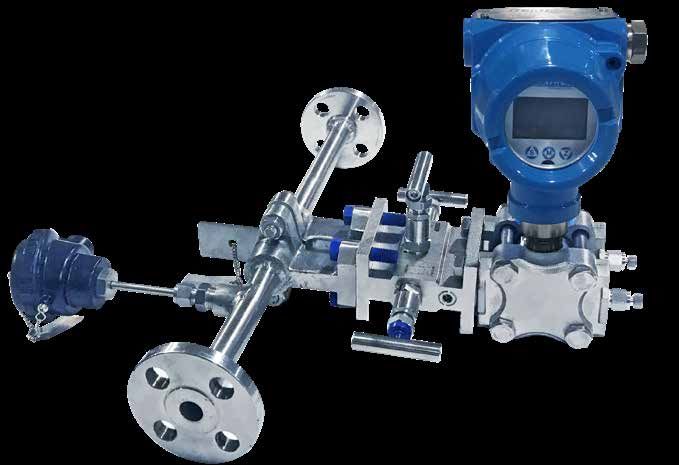
2. Unpack
Tek-DP 1610D Integral Orifice Assembly
3. Dimensional Drawing
- 900 Flange Class
Fig 1: Assembly without Associated Piping Fig 2: Assembly with Associated Piping
796 Tek Drive, Crystal Lake, IL 60014 USA +1 847 857 6076 +1 847 655 6147 www.tek-trol.comTechnology Solutions
4. Installations
• Straight Length Requirements
U D
(2d to d over a length of 1.5d to 3d)
Fig 3: Reducer
U D
Fig 4: Single 90° Bend Flow from One Branch
U D
Fig 5: Two or More 90° Bends in Same Planes
Tek-DP 1610DQuick Start Guide
U D
Fig 6: Two or More 90° Bends in Different Planes
U D
(0.5d to d over a length of d to 2d)
Fig 7: Expander
U D
Fig 8: Ball Valve or Gate Valve Fully Open
796 Tek Drive, Crystal Lake, IL 60014 USA +1 847 857 6076 +1 847 655 6147 www.tek-trol.comTechnology Solutions
Table 1: Required Straight Lengths for Orifice Plate, Nozzle
Upstream Side Downstream Primary
of Primary Devices (U1) Devices (D1)
Thermo-
Thermo- Fitting
Abrupt meter
Beta Single 90 Two or Two or Reducer Expander meter (All
Full bore symmetrical (pocket
Ratio bend or 0 more 90 0 more 90 2D to D 0.5D to D (pocket mentioned
Globe valve ball valve reduction or well*) of
tee (Flow bends in bends in over a over a or well*) of in Upstream
fully poen or gate valve having a diameter
from one the same different Length of Length of diameter Side of
fully poen diameter between
branch only) plane(*) planes 1.5D to 3D D to 2D =0.5Quick Start Guide
Table 2: Required Straight Lengths for Classical Venturi Tubes
Upstream Primary Devices (U1) Downstream
Primary
Devices (D1)
Beta Fitting
Ratio Two or Two or Reducer (All
Expander Full bore
more 90° more 90° 3D to D mentioned
Single 90° 0.75D to D ball valve
bends in bends in over a in Upstream
bend(*) over a or gate valve
the same different Length of Side of
Length of D fully poen
plane(*) plane(*)(**) 3.5 D Primary
Devices
0.30 0.5! 1.5 (0.5) (0.5) (0.5)! 1.5 (0.5) 1.5 (0.5) 4
0.35 0.5! 1.5 (0.5) (0.5) 1.5 (0.5) 1.5 (0.5) 2.5 (0.5) 4
0.40 0.5! 1.5 (0.5) (0.5) 2.5 (0.5) 1.5 (0.5) 2.5 (1.5) 4
0.45 1 (0.5) 1.5 (0.5) (0.5) 4.5 (0.5) 2.5 (1) 3.5 (1.5) 4
0.50 1.5 (0.5) 2.5 (1.5) (8.5) 5.5 (0.5) 2.5 (1.5) 3.5 (1.5) 4
0.55 2.5 (0.5) 2.5 (1.5) (12.5) 6.5 (0.5) 3.5 (1.5) 4.5 (2.5) 4
0.60 3 (1) 3.5 (2.5) (17.5) 8.5 (0.5) 3.5 (1.5) 4.5 (2.5) 4
0.65 4 (1.5) 4.5 (2.5) (23.5) 9.5 (1.5) 4.5 (2.5) 4.5 (2.5) 4
0.70 4 (2) 4.5 (2.5) (27.5) 10.5 (2.5) 5.5 (3.5) 5.5 (3.5) 4
0.75 4.5 (3) 4.5 (3.5) (29.5) 11.5 (3.5) 6.5 (4.5) 5.5 (3.5) 4
U2 14 18 31 7 15 10
*Note:
* The radius of curvature of the bend shall be greater than or equal to the pipe diameter.
** As the effect of these fittings may still be present after 40D, no values without parentheses can be
given.
! Since no fitting can be placed closer than 0.5D to the upstream pressure tapping in the Venturi Tube,
the “Zero Additional Uncertainty” values are only ones applicable in this case.
• All straight lengths are expressed in multiples of diameter D.
• Values without parentheses are “Zero additional Uncertainty” values.
• Values in parentheses are “0.5% additional Uncertainty” values.
796 Tek Drive, Crystal Lake, IL 60014 USA +1 847 857 6076 +1 847 655 6147 www.tek-trol.comTechnology Solutions
• For Gas
Tek-DP 1610D Integral Orifice Assemblies should be mounted above the pipe to ensure that condensate
does not collect on the transmitter sensing diaphragms
A
A
B
C
B
C
Fig 9: Direct Mount Gas in Horizontal Pipes
Where, A is 90° Recommended Zone
B is Vertical Plane
C is Horizontal Plane
If the fluid is flowing up, a direct mount Tek-DP 1610D should not be used in vertical gas applications
because of drain and vent orientation. Consider remote mounting the pressure transmitter to facilitate
condensate draining.
A
A
FLOW
Fig 10: Direct Mount Gas in Vertical Pipes
Where, A is 360° Recommended Zone.
Tek-DP 1610DQuick Start Guide
• For Liquid and Steam
Tek-DP 1610D Integral Orifice Assemblies should be mounted below the pipe to ensure that that gases do
not collect on the transmitter sensing diaphragms.
B C
B
C
A
A
Fig 11: Direct Mount Liquid or Steam in Horizontal Pipes
Where, A is 90° Recommended Zone
B is Vertical Plane
C is Horizontal Plane
If the fluid is flowing down, a direct mount Tek-DP 1610D should not be used in vertical liquid or steam
applications. Vertical installation for steam should be remote mount.
A
A
FLOW
Fig 12: Direct Mount Gas in Vertical Pipes
Where , A is 360° Recommended Zone.
796 Tek Drive, Crystal Lake, IL 60014 USA +1 847 857 6076 +1 847 655 6147 www.tek-trol.comTechnology Solutions
5. Electrical Connection
• Gas Measurement
Where, A is Vent
B is High Valve
C is Equalizer
D is Equalizer Valve
C
A
D
B
Fig 13: Direct Mount Gas Measurement
Where, A is Low Valve
A
B is Vent
C is High Valve
D D is Equalizer Valve
E is Block Valves
B
C
FLOW
E
Fig 14: Remote Mount Gas Measurement
Tek-DP 1610DQuick Start Guide
• Liquid Measurement
Where, A is Vent
B is Low Valve
C C is Equalizer Valve
D D is High Valve
A
B
Fig 15: Direct Mount Liquid Measurement
Where, A is Vent
B is High Valve
D
C is Equalizer Valve
D is Vent Valves
E is Low Valve
E
F F is Block Valves
C
FLOW
A
B
Fig 16: Remote Mount Liquid Measurement
796 Tek Drive, Crystal Lake, IL 60014 USA +1 847 857 6076 +1 847 655 6147 www.tek-trol.comTechnology Solutions
• Steam Measurement
Where, A is Vent
B is Low Valve
C C is Equalizer Valve
D D is High Valve
A
B
Fig 17: Direct Mount Steam Measurement
Where, A is Vent
B is High Valve
D
C is Equalizer Valve
D is Vent Valves
E is Low Valve
E
F F is Block Valves
C
FLOW
A
B
Fig 18: Remote Mount Steam Measurement
Tek-DP 1610DQuick Start Guide
6. Maintenance
• Check Flow Direction
o Check that the side of the orifice plate marked “Inlet” is facing upstream.
o If the DP transmitter is remote mounted from the Tek-DP 1610D, be sure that the
impulse tubing is connected correctly from the Tek-DP 1610D to the DP transmitter (high
to high and low to low).
• Check Orientation
o Improper orientation can result in inaccurate measurements.
• Check Zero
o The transmitter may read off in the high or low direction if not zeroed properly at start-up/
commissioning.
• Check Valves
o Equalizer valve is fully closed, high and low side valves are fully open to set the correct valve
for flow measurement.
• RTD Maintenance
To test the 4-wire RTD procedure as follows:
o Please power off the transmitter.
o Remove the temperature terminal housing cover.
o Disconnect the RTD lead wires from the terminal block.
o Separate the wires so that the un-insulated ends are not affecting.
o Check that the resistance measured between the two red wires and two white wires is
same (within +/- 0.1Ω).
o Note down the resistance value measured between the two white wires from next step.
o Measure the resistance between one red and one white wire. Subtract the resistance
measured in above step from the resistance measured in this step.
o If resistance matches the temperature that the RTD is in contact with it.
o Check the resistance between any wire and the RTD head or sheath and acceptable
resistance is 200KΩ or greater.
o If any of the above measurements are not within the acceptable range as stated above,
please contact a Tek-Trol representative for a RTD replacement.
o To return the RTD to service, connect the lead wires as shown in figure 21.
o Replace the Temperature Terminal Housing cover.
o Re-connect power to the transmitter.
796 Tek Drive, Crystal Lake, IL 60014 USA +1 847 857 6076 +1 847 655 6147 www.tek-trol.comTechnology Solutions
7. Troubleshooting
This section provides troubleshooting techniques for most common operating problems shown in
table 3.
Table 3: Troubleshooting Techniques
Symptom Possible Cause Corrective Actions
• Check flow arrow pointed in the direction of the flow.
Improper Installation • Verify that the cross reservoirs are correctly in level with one another.
• Check the sufficient straight runs upstream and downstream of the flow meter.
• Check instrument piping leaks.
System Leaks
• Repair and seal all leaks.
Contamination or Plugging • Remove the flow meter and check for contamination.
Questionable accuracy
or erroneous flow signal • Verify both High and Low manifold valves are open.
Closed Valve
• Verify vent, equalizer and line valves are properly positioned per start-up procedure.
Connections • Verify the high side of the transmitter is connected to the high side of the flow meter.
(remote mount only) • Check the same for the low side.
Entrapped Air (liquid and • Check uneven water legs caused by air entrapment in the instrument connections, if so, bleed
steam applications) air.
• Check the operating conditions in compliance with those given at the time the flow meter
Questionable accuracy was purchased.
Operating Conditions
or erroneous flow signal • Check the flow calculation and the fluid parameters for accuracy.
• Cross check pipe inside diameter for proper sizing.
• The flow meter is a head measurement device and will not measure a two-phase flow
Raising flow signal Two-phase flow
accurately.
Improper insulation (vertical • Additional insulation may be required to ensure a phase change occurs at the cross reservoirs.
Raising flow signal (Stream • Check the impulse piping for vibration.
pipes only), Excessive
Service)
vibration
• Check if the power terminals are reversed.
• Verify voltage across terminals (should be 10 to 55VDC).
mA reading is zero
• Check for bad diode in terminal block.
• Replace the transmitter terminal block.
• Check power supply voltage of the transmitter (10.5VDC minimum).
Transmitter is not • Check load resistance (250Ω minimum).
communicating • Check if the unit is addressed properly.
• Replace the Transmitter.
• Check pressure variable reading for saturation.
• Check if output is in alarm condition.
mA reading is high or low
• Perform 4–20mA output trim.
• Replace Transmitter.
• Check test equipment.
• Check impulse piping for blockage.
No response to changes in • Check for disabled span adjustment.
applied flow • Check transmitter security switch.
• Verify calibration settings (4 and 20mA points).
• Contact factory for replacement.
• Check impulse piping for blockage.
• Check test equipment.
Low or High reading
• Perform full sensor trim.
• Contact factory for replacement.
• Check impulse piping for blockage.
Unpredictable reading for • Check damping.
pressure variable • Check for EMF interference.
• Contact factory for replacement.
Tek-DP 1610DQuick Start Guide
Tek-Trol LLC
796 Tek Drive Crystal Lake, IL
60014, USA
Sales: +1 847-857-6076
Tek-DPro Flow Solutions Tek-Trol Solutions BV Tek-Trol Middle East FZE
PO Box 121 Windsor, Colorado Florijnstraat 18, 4879 AH SAIF Zone, Y1-067, PO BOX No.
80550, USA Etten-Leur, Netherlands 21125, Sharjah, UAE
Sales: +1 847-857-6076 Sales: +31 76-2031908 Sales: +971-6526-8344
Support: +1 847-857-6076 Email: tektrol@tek-trol.com www.tek-trol.com
796 Tek Drive, Crystal Lake, IL 60014 USA +1 847 857 6076 +1 847 655 6147 www.tek-trol.comYou can also read