Q-CAM: Queue Monitoring System using Camera - Annals of ...
←
→
Page content transcription
If your browser does not render page correctly, please read the page content below
Annals of Emerging Technologies in Computing (AETiC)
                                                                                  Vol. 5, No. 5, 2021

Research Article

         Q-CAM: Queue Monitoring System
                 using Camera
      Farah Nadiah Mohammad Ramlee, Radzi Ambar*, Mohd Helmy Abd Wahab, Chew
                    Chang Choon and Muhammad Mahadi Abd Jamil
                            Universiti Tun Hussein Onn Malaysia, Johor, Malaysia
         farahnadiah_mr@yahoo.com; helmy@uthm.edu.my; ccchew@uthm.edu.my; mahadi@uthm.edu.my
                                  *Correspondence: aradzi@uthm.edu.my

  Received: 17th October 2020; Accepted: 20th December 2020; Published: 20th March 2021
Abstract: Development and design of mobile queue counter monitoring system is an alternative way for
people who visit service premises to monitor queue number through phone without having to be at the place
to wait for their turn. A long waiting line and waiting time are the reasons why this project had been
developed. Many related systems had been introduced by different companies but due the high cost of
installation and maintenance, some service companies had difficulties to implement the system. However,
the proposed mobile queue counter monitoring system called Q-CAM is an add-on device which will be
installed with the existing system and uses only ESP32 camera and FTDI Programmer as hardware
development. A smartphone application is developed by using MIT App Inventor to ease the customer to
monitor queue number on the app. In this work, the hardware designs of the propose device is described.
Furthermore, the steps to develop the smartphone app is demonstrated. Preliminary experimental results
show that the average time required to display a captured queue number image on the app were 5 seconds
(during strong Wi-Fi signal) and 10.8 seconds (during weak Wi-Fi signal).

Keywords: Queue monitoring system; ESP32 camera; smartphone application; Wi-Fi; QMS

1. Introduction
     Queuing system in a customer service can be described as a system where the arrival of
customers is the input and the served customer as the output. Usually in this system, the aim is to
control customer flow and the customer has to wait for their turn to get the service. There are various
queue systems currently implemented in Malaysia that had been implemented at most establishment
such as in finance, government and healthcare sectors that manage customer flow and queues1. This
system had been used since decades ago and became the main queue system utilized in Malaysia.
These systems are necessary to ensure disciplined and efficient guided-customer service.
     Basically, queuing is a line of people or things waiting for their turn to be handled normally in
a first-come-first-handled order. However, problem arises when queue become longer than
anticipated and increase wait times which leads to the prime reason of customer dissatisfaction 2.
Customer services-oriented companies have been encountering difficulties of long line queue.
Premises tend to get crowded especially during peak periods and also can cause some queuing
problems such as balking and reneging. Balking means customers that refuse to join the queue for
services, while reneging is when the customer decided to leave the queue after waiting too long for

1
    https://blog.wavetec.com/en/queue-management-system-in-malaysia
2https://www.thestar.com.my/news/nation/2019/02/28/apad-investigating-video-of-man-losing-his-cool-says-he-hadnt-

waited-that-long/

Farah Nadiah Mohammad Ramlee, Radzi Ambar, Mohd Helmy Abd Wahab, Chew Chang Choon and Muhammad Mahadi
Abd Jamil, "Q-CAM: Queue Monitoring System using Camera”, Annals of Emerging Technologies in Computing (AETiC), Print
ISSN: 2516-0281, Online ISSN: 2516-029X, pp. 137-145, Vol. 5, No. 5, 20th March 2021, Published by International Association of
Educators and Researchers (IAER), DOI: 10.33166/AETiC.2021.05.017, Available: http://aetic.theiaer.org/archive/v5/v5n5/p17.html.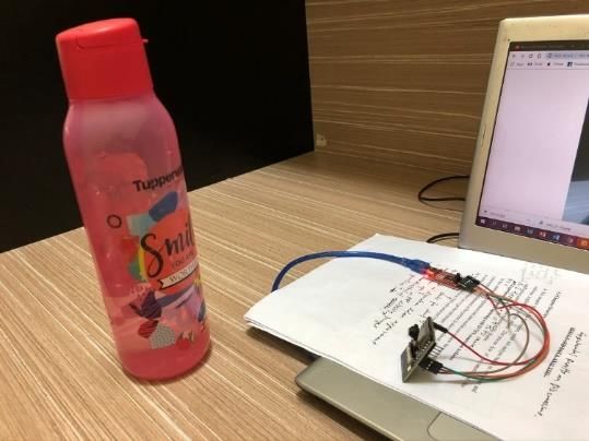
AETiC 2021, Vol. 5, No. 5                                                                                           138

the services3. Therefore, a queue management system (QMS) must handle and organizes queue
arrangement effectively.
     Conventional ways to handle queues such as distributing paper tickets printed with queue
number lead to several issues such as littering paper tickets and long queues or wait times at
premises. Alternative ways to solve this problematic customers’ queuing experiences are by
implementing e-services or mobile QMS. A work done in [1] proposed a QMS which can generate
and send queue number via SMS. Lin et al. [2] proposed a smartphone app based QMS that displays
pops up notification messages to customer using Bluetooth beacon technology. A study in [3]
proposed a smartphone app based QMS that enable restaurant customers to view, book and manage
his/her queue prior arrival to the restaurant. There are also studies such as [4] and [5] that propose
queue waiting time estimation based on numerical simulation to minimize waiting time. A QMS has
been implemented in a hospital that can display real-time queue data and also room availability via
smartphone and website 4. Based on the above, mobile QMSs are becoming an interesting research
area where new devices and mobile applications are introduced. However, premise owners tend to
use existing queue counter display that they have invested in their premises. There are QMSs that are
commercially available, where real-time images from cameras are used to update queue number,
expected wait time and time of entry that can be monitored via mobile device 5, 6. However, the
systems are costly and involve complex implementation.
     Thus, this paper describes the design and development of a mobile queue counter monitoring
system using camera called Q-CAM. The objectives of the work are two-fold; to provide an alternative
way to reduce waiting time at premises using smartphone, and also reduce mobile QMS
implementation costs where the system serves as an add-on device for existing queue counter display
in premises. This paper is organized as follows. Section 2 describes the detail design of the proposed
Q-CAM including hardware and software components. Section 3 introduces the design of the system.
Then, section 4 discussed the experiments to show the usefulness and performance of Q-CAM in
achieving the objectives, followed by a brief conclusion and future recommendation in section 5.

2. Proposed Method
     This section describes the project overview, project design, methods, hardware and software
requirement that will be used in this project. Figure 1 shows the block diagram of the proposed
mobile2 queue counter monitoring system. This project is an add-on device for any existing queue
counter devices used in premises. The input of the device is the captured images of the turn number
displayed on the queue counter. As shown in the figure, the hardware parts utilized in the device are
an ESP32 camera and an FTDI (Future Technology Devices Interglobal) Programmer. The camera
captures images that are transmitted to an Android-based smartphone application (app) built
specially for the queue counter monitoring system. In this app, user is able to monitor and see the
current queue number at the premise by the image captured from the camera from remote location.

2.1. Hardware Components
     As shown in Figure 1, an ESP32 camera module is used in this project to capture the turn
numbers from queue counter display. The ESP32 camera is a small-sized module that can operate
independently as a minimum system with a footprint of only 27mm x 40.5mm x 4.5mm and a deep
sleep current of up to 6Ma. It consists of two parts which are the main board that is an ESP32 module
mounted on a larger board and a separate camera module. A flex cable from the camera slots into the
main board that is based on an ESP32 module. The module is a programmable mic rocontroller with
built-in Wi-Fi and Bluetooth, with an additional 4MB of external RAM.

3 https://www.americaninno.com/boston/jockeying-faffing-balking-the-science-behind-waiting-in-line-from-mit/

4   https://hampg.moh.gov.my/qms/#!/
5   https://www.retailsensing.com/queue-management.html

                                                                                                   www.aetic.theiaer.org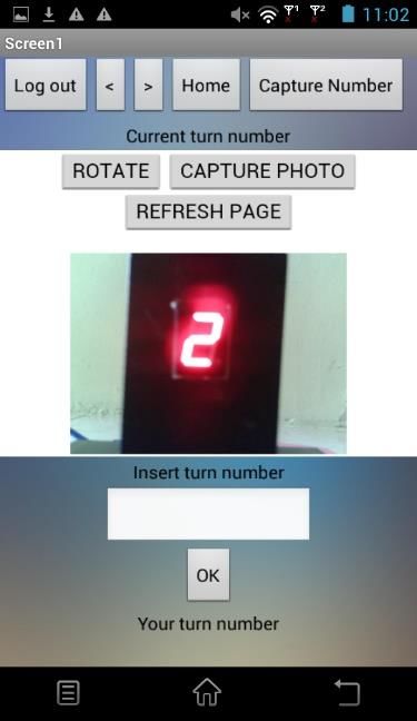
AETiC 2021, Vol. 5, No. 5                                                                                    139

     The board is equipped with a memory card slot and a camera connector that can be connected
to an OV2640 camera module. However, the memory card is not used in this project development. In
this work, once a new image is captured, the previous captured image will be deleted.
     Since this is a Wi-Fi enabled camera, IP address is required in order to observe the captured
images on camera control page. Figure 2 shows the IP address printed on the computer’s serial
monitor after the source code was uploaded into ESP32 camera module. Then, the IP address can be
typed on a web browser to access camera streaming server on local network. These steps are
necessary to operate the ESP32 camera module. Table 1 shows ESP32 camera specifications.
     Figure 1 also shows a FTDI programmer that is used in this project. The FTDI programmer works
for converting TTL (Transistor–Transistor Logic) serial transmission to USB signals, where it is used
to upload the source codes from personal computer (PC) to ESP32 board via the U0RXD and U0TXD
serial pins. This is done due the fact that there is no USB port on ESP32 board to be connected to the
PC. This adapter support both 3.3V and 5V operations.

                 ESP32 Camera

                FTDI programmer

                    Hardware                                                Smartphone application
                            Figure 1. Overview of the proposed queue monitoring system

                                                                       IP address

                                          c

                                  Figure 2. IP address displayed in serial monitor

                                                                                            www.aetic.theiaer.org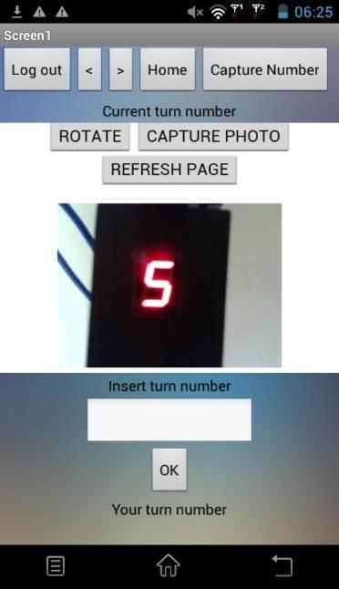
AETiC 2021, Vol. 5, No. 5                                                                                          140

                                         Table 1. ESP32 Camera Specifications
                 Module model                  ESP32-CAM
                 Package                       DIP-16
                 Size                          27*40.5*4.5
                 SPI flash                     Default 32 Mbit
                 RAM                           520KB SRAM + 4M PSRAM
                 Bluetooth                     Bluetooth 4.2 BR/EDR and BLE standard
                 Wi-Fi                         802.11 b/g/n
                 Support interface             UART, SPI, I2C, PWM
                 Support TF card               Maximum support 4G
                 IO port                       9
                 UART baudrate                 Default 112500 bps
                 Image output format           JPEG (OV2640 support only), BPM, Grayscale

2.3. Software Requirements
     Arduino integrated development program (IDE) is used to program the source codes for the
ESP32 board. Therefore, the IDE should be installed in the ESP32 board prior to be used. The ESP-32
board is uploaded with the source code that can sends commands to capture image and send the
image to a smartphone application via Wi-Fi. This work uses a web application development
environment called MIT App Inventor to create application software (app) for smartphones and
tablets. This app inventor can only develop application for Android phone using a web browser and
either a connected phone or emulator.

3. Design of the System
3.1. Circuit Design
     Figure 3(a) shows an illustration of the circuit connection between ESP32 camera module and
FTDI programmer. As shown in the figure, the circuit is simple, where the ESP32 camera is connected
with FTDI programmer via four wire connections as this camera module does not come with USB
connector. The FTDI programmer works for converting TTL serial transmission to USB signals, and
also to upload source code from a PC through the UOR and UOT pins (serial pins). Figure 3(b) shows
the experimental setup to test ESP-32 Cam with FTDI programmer. The figure shows the connection
of the ESP32 camera module with the FTDI programmer. Detail of the experiment is discussed in the
next section.

                                       ESP32-Cam

      Personal computer
                                                                                      FTDI programmer

                                                                   Target
        FTDI Programmer                                            object
                                                                            ESP32 camera module

                            (a)                                                             (b)
 Figure 3. (a) Circuit connection for ESP32 camera module with FTDI programmer, (b) the actual experimental
                                           setup to test ESP32 camera

3.2. Android-based Smartphone Application Design
    As described in the previous section, the Android-based smartphone app is developed using
MIT Apps Inventor on a personal computer. Basically, there are two ways to test the app developed

                                                                                                  www.aetic.theiaer.org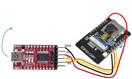
AETiC 2021, Vol. 5, No. 5                                                                                 141

using the MIT Apps Inventor; (a) using Android Package (APK) file of the developed app and saved
it in ZIP format to be downloaded directly to Android smartphone, or (b) scanning the QR code
obtained from MIT App inventor. In this work, method (b) was selected because the developed app
can be tested in real-time on any Android-based smartphone. However, another app called MIT AI2
Companion app needs to be downloaded in an Android smartphone beforehand to scan the QR code
from MIT Apps Inventor that can automatically download and test the developed app.
      Based on several tests, it is found that a strong Wi-Fi connection is crucial in order to send the
captured image from ESP32 camera module to the developed app. Furthermore, the method of
scanning the QR code to download and test the developed the app has a drawback where the QR
code is valid to be used within 2 hours only, and user is required to get new QR code after 2 hours.
However, this is enough for a short period of testing purposes.
      Figure 4 shows the developed Android-based smartphone app for queue monitoring system.
Figure 4(a) shows the condition when the app receives the captured image successfully. Figure 4(b)
shows the condition when the apps is unsuccessful to receive image due to low connection of Wi-Fi.

                               (a)                                     (b)
Figure 4. The developed smartphone app. (a) Image received successfully, (b) Unsuccessful in receiving image
     As shown in Figure 4(a), the single app page consists of three parts. On the top half of the app,
there are Log out, Home, Search and scroll (left and right) buttons. The Log out button is to exit from the
app. Home button is to refresh the page. As the app is in preliminary test version, the scroll and search
buttons are not used. At the center of the page shows the internet web browser that displays the
captured image taken from the ESP32 camera. The web browser is opened based on the IP address
from ESP32 camera. As shown in Figure 4(b), the web browser displays ROTATE, CAPTURE PHOTO
and REFRESH PAGE buttons. When CAPTURE PHOTO button is pushed, it will instruct the ESP32
camera to capture an image to be sent to the app. REFRESH PAGE button is to refresh the page if the
capture image is not displayed. Currently, the ROTATE function is not being used. On the lower half
of the page shows a text box to type customer’s turn number. OK button is clicked to save the turn
number in the app so that the customer can easily keep reference of turn number.

4. Experimental Steps and Results
     There are two experiments that have been carried out in this work. The first experiment is to
verify the usefulness of the ESP32 camera in capturing a target object. The second experiment is to

                                                                                         www.aetic.theiaer.org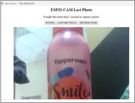
AETiC 2021, Vol. 5, No. 5                                                                                    142

show the performance of the developed app to display the captured image from ESP32 camera. The
detail of each experiment is described in the next subsections.

4.1. Experiment on ESP32 Camera
     Figure 3(b) shows the experimental setup for verifying the usefulness of ESP32 camera. As
shown in the figure, the ESP32 camera is connected with FTDI programmer. The ESP32 camera is
positioned in front of a target object which is a water bottle.
     Experimental Steps. First, ESP32 camera is connected to FTDI programmer. 5V power is used
supply to power FTDI programmer. Then, source code is uploaded to FTDI programmer. After the
code uploaded successfully, serial monitor is opened to get the IP address. The IP address is copied
and pasted on the internet browser. The camera is placed in static position in front of the object to
capture a good image. Then, the camera starts to capture image after clicking CAPTURE PHOTO
button. Finally, the test image can be observed through internet browser.
     Experimental Results. As ESP32 Cam is a Wi-Fi-enabled camera, obtaining IP address after
uploading the code is an important step prior to view the test image. Then, the camera server can be
access on local network by inserting the IP address on the internet browser to view the captured
image. Figure 5(a) shows how the IP address for the ESP32 is obtained after the code is uploaded into
the ESP3 board. The IP address should be displayed on the serial monitor on the condition that the
camera received a strong Wi-Fi connectivity. Otherwise, it would not have displayed the IP address
on serial monitor as shown in Figure 5(b).

                                  IP address

                     c

                            (a)                                                 (b)
Figure 5. (a) Getting the IP address after downloading the code. (b) No IP address displayed due to weak WiFi
                                                  connection

       Insert IP
      address here

                            (a)                                                 (b)
                Figure 6. (a) Test image. (b) Serial monitor showing the captured images are saved
    Next, by inserting the IP address on the internet browser, the test image can be viewed
immediately after capturing a picture as shown in Figure 6(a). The average time taken to display a
captured image during this experiment was approximately 5 seconds. The quality of the image taken

                                                                                            www.aetic.theiaer.org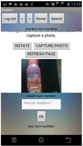
AETiC 2021, Vol. 5, No. 5 143
using this camera is much better compared to OV7670 camera module that we have tested. The ESP23
camera produces coloured and clear image. Just by clicking on CAPTURE PHOTO button, new image
will be captured and saved as shown in serial terminal in Figure 6(b).
Discussion. In this experiment, ESP32 camera functioned well as it produced a better quality
image in short time. As described previously, low-cost camera such as OV7670 module only produces
monochrome images. However, ESP32 camera is able to produce coloured images. Furthermore, it
has been observed that the procedures to capture images are simpler and more convenient which is
suitable to be applied in this project. However, the downside of this camera module is, it requires a
strong Wi-Fi connection to smoothen the camera operation. As a solution, for experimental purposes,
the camera will be connected to personal hotspot device to make the whole system works perfectly.
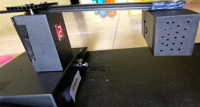
4.2. Queue Counter Monitoring System Experiment
A full test operation of the proposed queue counter monitoring system have been carried out to
verify the performance of the system. Figure 7 shows the experimental setup. The ESP32 camera and
FTDI programmer are packaged in the small black box with an opening for the camera to capture
images. In front of the camera is a mock-up single number queue counter. A button is located below
the queue counter to change the turn number displayed using a 7-segment display.
Turn number
Push button
Mock-up queue counter display ESP32 camera box
Figure 7. Serial monitor showing the captured images are saved
Experimental Steps. First, the queue counter and ESP32 camera is turned ON. After start up the
developed smartphone app, “Capture number” button is pushed to access ESP32 camera server. Click
CAPTURE PHOTO button to capture image. Then, click REFRESH PAGE button to display the
captured image on the app. Push the push button on the queue counter to change the turn number.
Then, repeat step 4 to 6 to display the captured image on the app.
Experimental Results. In this experiment, the 7-segment can display numbers from 0 to 9 to
represent the turn number for a queue counter in a real situation. This 7-segment is controlled
manually by pressing the push button as shown in Figure 7. In a real situation, the user of the app
can use obtain the current turn number from remote location. However, the user must download the
developed app. Figures 8 shows the captured image which display different turn number from the 7-
segment display.
Discussion. After experimenting with the system, it is found that strong Wi-Fi connection plays
an important role in order to operate the system perfectly. This experiment have also tested the effect
of low and high Wi-Fi connection towards the performance of transmitting the captured image from
ESP32 camera to the smartphone app. The time taken to capture and display captured images from
ESP32 camera to smartphone app were observed and recorded. The speed of the Wi-Fi connection is
represented by signal bar on Wi-Fi signal indicator on the smartphone as shown in Figure 9.
www.aetic.theiaer.org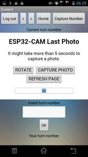
AETiC 2021, Vol. 5, No. 5                                                                                      144

                               Figure 8. The app displays turn number 2 and 5

                              Weakest                                        Strongest
                                   Figure 9. Wi-Fi signal strength indicator
     First, both camera and smartphone were connected to low Wi-Fi connection. A stop watch was
used to record the time taken from the step 1 in the experiment steps above until the turn number
image is displayed on the developed apps. First, experimental steps 1 to 4 in the experiment steps
above were carried out, then, if no image displayed, the CAPTURE PHOTO button was clicked
concurrently until the turn number image was displayed and the time taken was recorded. The same
experiment steps were carried out high Wi-Fi connection. The steps above were repeated for each
turn number from 0 to 9 for each low and high Wi-Fi connection to observe the camera performance.
     Tables 2 shows the comparison of the time taken to display the queue number images during
weak and strong Wi-Fi signals respectively. From the experiment, the average time required to
display the captured images when both camera and smartphone were connected to weak signal
strength was 10.8 seconds. However, it took an average time of 5 seconds to display the captured
images on the app when Wi-Fi signal was strong. There are few possibilities on why it took longer
time to display images when the camera is connected to weak Wi-Fi connection, and device
interference is one of the causes. Sometimes intermittent signal can occur caused by interference from
other devices hence it can disturb Wi-Fi signal strength. Moreover, one of the most common causes
of weak Wi-Fi connection is distance between the ESP32 camera and smartphone. It is found that
since the camera is connected to a personal hotspot device, the mobile device should be placed closer
to the receiver to obtain stronger signal.
               Table 2. Comparison of the time taken to display queue number images on the app
                                    during weak and strong Wi-Fi signals
                                                            Time Taken (s)
             Queue Number
                                 During weak Wi-Fi signal              During strong Wi-Fi signal
                     0                      13                                           7
                     1                      12                                           4
                     2                      12                                           4
                     3                      11                                           5
                     4                      10                                           5
                     5                      10                                           5
                     6                      9                                            4

                                                                                              www.aetic.theiaer.org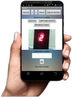
AETiC 2021, Vol. 5, No. 5                                                                                  145

                     7                        10                                 6
                     8                        11                                 5
                     9                        10                                 6

5. Conclusion
      Mobile queue counter monitoring system is useful for customer in premises such as post office,
clinics and banks where the user can monitor their turn number without having to be at the premise
for hours while waiting for their turn. In this work, a low-cost mobile queue counter monitoring using
ESP32 camera called Q-CAM have been developed successfully. Q-CAM is able to capture images
and the smartphone app can display the captured images. The results from the experiments show
that the system operated effectively and achieved the objectives. It is also found that strong Wi-Fi
connection is required for prompt display of image on app. Future work may consists of adding
multiple image displays in the app, in a situation where multiple queue counter exists in premise.
Further upgrades and experiments will be carried out to improve the performance of the system.

Acknowledgement
     The authors would like to thank the Research Management Center (RMC), UTHM and Ministry
of Higher Education for sponsoring the research under Tier 1 Research Grants (H161).

References
[1] Aiman ZJ, Norfadzlia MY, Tole S (2016) Arduino Based Paperless Queue Management System, Telkomnika,
    vol. 14, no. 3, pp. 839-845, doi: http://dx.doi.org/10.12928/telkomnika.v14i3.3114.
[2] Lin C, Jhu G and Siao S (2019) An Innovative Queue Management System Based on Bluetooth Beacon
    Technology. 2019 IEEE Int. Conf. on Comp. Sci. & Eng. (CSE) and IEEE Int. Conf. on Embedded and
    Ubiquitous Computing (EUC), New York, NY, USA, 2019, pp. 427-430, doi: 10.1109/CSE/EUC.2019.00085.
[3] Ramasamy R, Haw S, Chua F (2018) Casual dining restaurant queue management system to optimize
    decision making in table seating arrangement. Knowledge Management Int. Conf. (KMICe), pp. 18-22,
    Available: http://www.kmice.cms.net.my/ProcKMICe/KMICe2018/pdf/CR8.pdf.
[4] Patel JJ, Chaudhary RM, Patel PA, Makwana P (2012) Minimize the Waiting Time of Customer and Gain
    more Profit in Restaurant using Queuing Model. Int. J. of Eng. Res. and Appli. (IJERA) 2(3): p.1422-1425,
    Available: http://www.ijera.com/papers/Vol2_issue3/IL2314221425.pdf.
[5] Hermanto RPS, Suharjito, Diana, Nugroho A (2018) Waiting-Time Estimation in Bank Customer Queues
    using RPROP Neural Networks. Procedia Computer Science, vol. 135, pp. 35-42, doi:
    https://doi.org/10.1016/j.procs.2018.08.147.

                         © 2020 by the author(s). Published by Annals of Emerging Technologies in Computing
                         (AETiC), under the terms and conditions of the Creative Commons Attribution (CC BY)
                         license which can be accessed at http://creativecommons.org/licenses/by/4.0.

                                                                                          www.aetic.theiaer.org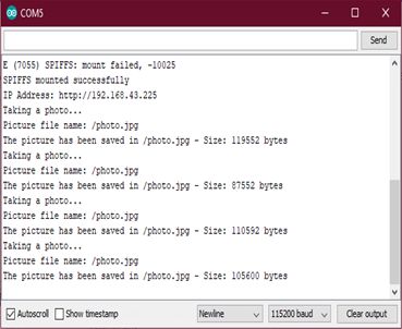
You can also read


