Operating & Safety Instructions Instructions et la sécurité de fonctionnement Instrucciones de funcionamiento y seguridad - One Ladder Does It All
←
→
Page content transcription
If your browser does not render page correctly, please read the page content below
Operating & Safety Instructions
                       •
Instructions et la sécurité de fonctionnement
                       •
Instrucciones de funcionamiento y seguridad

              One Ladder Does It All
                                       ®
One Ladder Does It All
®
STEPLADDER MODE / MODE ESCABEAU / MODO ESCALERA DE TIJERA
90-DEGREE MODE / MODE À 90 DEGRÉS / MODO EN 90 GRADOS
SCAFFOLDING TRESTLE MODE / MODE ÉCHAFAUDAGE / MODO DE CABALLETE DE ANDAMIO
*Plank and trestle brackets *madrier d'échafaudage et fixations *andamio y los soportes del caballete
sold separately du chevalet vendu séparément vendido por separado
STAIRCASE MODE / MODE ESCALIER / MODO PARA ESCALONES
UNEVEN SURFACES / SURFACE EN PENTE / SUPERFICIE INCLINADA
STRAIGHT LADDER MODE / MODE ÉCHELLE DROITE / MODO ESCALERA RECTACongratulations on your purchase of a LITTLE GIANT® ladder!
These instructions will help you make the most of your LITTLE GIANT ladders by learning how
to use it safely. Please do not ignore the instructions, study them! If you have questions
about how to operate your ladder, please search our safety resources at
www.LittleGiantLadders.com/SafetyToolbox, scan the QR code, or call us before using your
ladder. Your safety and satisfaction is most important to us.
Welcome to the LITTLE GIANT family!
Customer Experience Team: 800-453-1192 • Monday - Friday, 7 a.m. - 6 p.m. MST
Little Giant Ladder Systems • 1198 North Spring Creek Place • Springville, UT 84663 • USA
www.LittleGiantLadders.com
Félicitations d'avoir acheté une échelle LITTLE GIANT®!
Ces instructions vous aideront à tirer profit au maximum de votre échelle LITTLE GIANT en
apprenant comment l’utiliser en toute sécurité. N'ignorez pas les instructions, étudiez-les!
Si vous avez des questions sur la façon d'utiliser votre échelle, nous vous invitons à effectuer
une recherche dans nos ressources sur le site www.LittleGiantLadders.com/SafetyToolbox,
balayez le code QR ou contactez-nous avant d'utiliser celui-ci. Votre sécurité et votre
satisfaction nous tiennent véritablement à cœur.
Bienvenue dans la famille de LITTLE GIANT!
Équipe de service à la clientèle : 800-453-1192 • Du lundi au vendredi de 7 h à 18 h HNR Little
Giant Ladder Systems • 1198 N. Spring Creek Place • Springville, UT 84663
www.LittleGiantLadders.com
¡Felicitaciones por comprar una escalera LITTLE GIANT®!
Estas instrucciones le enseñarán a usar su escalera LITTLE GIANT de manera segura y así
podrá aprovecharla al máximo. Sigas estas instrucciones y memorícelas. Si tiene alguna
pregunta sobre cómo usar su escalera, busque nuestros recursos de seguridad en línea en
www.LittleGiantLadders.com/SafetyToolbox, escanee el código QR o comuníquese con
nosotros antes de usar la escalera. Su seguridad y su satisfacción son lo más importante para
nosotros.
¡Bienvenido a la familia LITTLE GIANT!
Equipo de atención al cliente: 800-453-1192 • De lunes a viernes de 7 a. m. a 6 p. m.,
MST (hora de la montaña)
Little Giant Ladder Systems • 1198 North Spring Creek Place • Springville, UT 84663 • EE. UU.
www.LittleGiantLadders.com
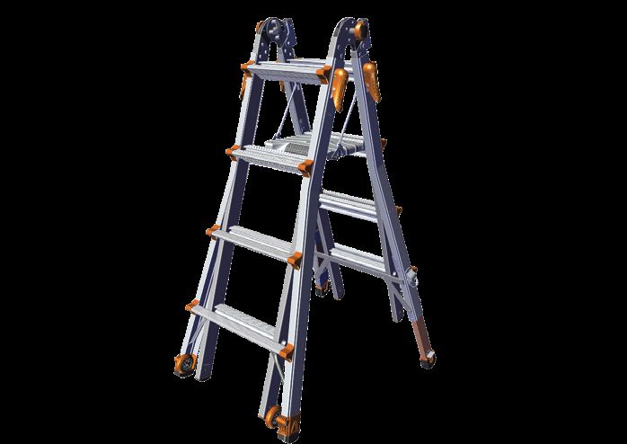
3Get to know your new Little Giant® ladder!
Apprendre à connaître votre nouvelle échelle Little Giant!
¡Llegar a conocer su nueva escalera Little Giant!
Accessory Port*
Port d'accessoires* Hinge Lock
Puerto para accesorios* Dispositifs de retenue
Traba de bisagra
Inner Ladder Assembly
Assemblage interne de l’échelle
Parte interior de la escalera
Outer Ladder Lock
Système de verrouillage
pour l’échelle externe
Las trabas externas de
la escalera
COMFORT STEP™ Platform*
Plateforme COMFORT STEP*
Plataforma COMFORT STEP*
RATCHET™ Levelers*
Niveleurs RATCHET*
Niveladoras RATCHET*
TIP & GLIDE™ Wheels* Outer Ladder Assembly
Roulettes TIP & GLIDE* Assemblage externe de l’échelle
Ruedas TIP & GLIDE* Parte exterior de la escalera
*Depending on your ladder model, these items may or may not be included or available.
*Selon le modèle de l'échelle, ces éléments peuvent ou non être inclus ou disponible.
*Dependiendo del modelo de escalera, estos artículos pueden ser o no ser incluidos o disponibles.
4Table of Contents
Table des matières
Tabla de contenido
English
Introduction - LITTLE GIANT® Ladder Basics ............................................................................... 6
Operating and Adjusting the Ladder.............................................................................................. 7 EN
The Hinges ............................................................................................................................ 7
The Outer Ladder Locks........................................................................................................ 8
General Operating Safety Tips .............................................................................................. 9
Stepladder Mode Instructions.............................................................................................. 10
Staircase Mode Instructions ................................................................................................ 10
Straight Ladder Mode Instructions ...................................................................................... 11
90° Mode Instructions.......................................................................................................... 12
Scaffolding Trestles Instructions.......................................................................................... 12
TIP & GLIDE™ Wheel Instructions ..................................................................................... 14
AIRDECK® Workstation Instructions.................................................................................... 15
COMFORT STEP™ Platform Instructions........................................................................... 16
RATCHET™ Leveler Instructions ........................................................................................ 16
Ladder Maintenance Instructions ................................................................................................ 17
Little Giant Warranty.................................................................................................................... 19
Standards Compliance and Certifications ................................................................................... 19
Preoperational Inspection Checklist ............................................................................................ 21
Français
Introduction - Éléments de base de l’échelle LITTLE GIANT® .................................................... 22
Utiliser et ajuster l’échelle............................................................................................................ 23 FR
Les charnières..................................................................................................................... 23
Système de verrouillage pour l’échelle externe................................................................... 24
Consignes de sécurité pour l’utilisation générale ................................................................ 25
Instructions du mode escabeau .......................................................................................... 26
Instructions du mode escalier.............................................................................................. 26
Instructions pour l’échelle droite.......................................................................................... 27
Instructions pour le mode à 90 degrés ................................................................................ 28
Instruction pour le mode chevalet d’échafaudage............................................................... 28
Instructions pour les roulettes TIP & GLIDE™ .................................................................... 30
Instructions pour la station de travail AIRDECK® ................................................................ 31
Instructions de la plateforme COMFORT STEP™ .............................................................. 32
Instructions du dispositif de mise à niveau RATCHET™ .................................................... 32
Instructions pour l’entretien de l’échelle ...................................................................................... 33
Garantie Little Giant .................................................................................................................... 35
Certifications et conformité aux normes ...................................................................................... 35
Liste d’inspection de l’échelle avant chaque utilisation ............................................................... 37
Español
Introducción - Información básica de la escalera LITTLE GIANT® .............................................. 38
Uso y ajuste de la escalera ......................................................................................................... 39 ES
Las bisagras ........................................................................................................................ 39
Las trabas externas de la escalera ..................................................................................... 40
Consejos generales de seguridad de uso ........................................................................... 41
Instrucciones para el modo escalera de tijera..................................................................... 42
Instrucciones para el modo para escalones........................................................................ 42
Instrucciones para el modo de escalera recta..................................................................... 43
Instrucciones para el modo de 90 grados ........................................................................... 44
Instrucciones para el modo de caballete de andamio ......................................................... 44
Instrucciones para las ruedas TIP & GLIDE™ .................................................................... 46
Instrucciones para la estación de trabajo AIRDECK® ......................................................... 47
Instrucciones para la plataforma COMFORT STEP™ ........................................................ 48
Instrucciones para las niveladoras RATCHET™................................................................. 48
Instrucciones de mantenimiento de la escalera .......................................................................... 49
Garantía de Little Giant ............................................................................................................... 51
Cumplimiento de normas y certificaciones .................................................................................. 51
Lista de verificación de inspección preoperativa de la escalera ................................................. 53 5Operating Instructions for Little Giant® articulated extendable ladders
I. Introduction - LITTLE GIANT® Ladder Basics
A. Articulated Extendable Ladder Unit - The ladder is comprised of three basic components
EN - an inner ladder assembly and two outer assemblies which telescope over the inner.
1. The inner assembly has 2 locking hinges which allow the ladder system to be used in the
following configurations:
1 2 3
Storage Stepladder Straight Ladder
2. Locking mechanisms on the two outer assemblies permit the ladder to be adjusted in
length. These locking mechanisms fit into any rung on the inner assembly, allowing
rung-by-rung adjustment on either end of the ladder. In addition to being able to use the
ladder in multiple sizes of the stepladder and straight ladder modes mentioned above,
since the outer sections can be adjusted independently of one another, or completely
removed from the inner, this allows for the following additional configurations.
4 5 6
90-degree Staircase Scaffolding Trestles
NOTE: Some models require optional trestle brackets in order for the ladder to be used as
scaffolding trestles.
NOTE: Scaffolding plank sold separately.
B. Model Specification Table*
Model Storage Height Stepladder Height Straight Ladder Height
M13 3’ 7” [1.09 m] 3’–5’ [0.9 m–1.5 m] 7’–11’ [2.1 m–3.4 m]
M17 4’ 7” [1.40 m] 4’–7’ [1.2 m–2.1 m] 9’–15’ [2.7 m–4.6 m]
M22 5’ 7” [1.70 m] 5’–9’ [1.5 m–2.7 m] 11’–19’ [3.4 m–5.8 m]
M26 6’ 7” [2.00 m] 6’–11’ [1.8 m–3.4 m] 13’–23’ [4.0 m–7.0 m]
* Since this is a general guide for multiple models, all specifications are approximate. For exact
specifications of your particular model, please visit our website or contact our Customer
Experience Team at 800-453 1192.
6II. Operating and Adjusting the Ladder
A. The Hinges - Located at the top of the ladder when it is in the storage position. They permit
you to alter the shape of the ladder.
1. Unlocking Hinge Locks - Depending on your particular ladder model, it will have one of EN
the following hinge lock styles:
7 8 9
a) Push-style
Unlock the hinges by pushing straight in on the palm buttons until they
stay in the open (unlocked) position on both hinges (Fig. 9).
10 11 12
b) Pull-style
Unlock the hinges by pulling straight out on the hinge lock castings until
they stay in the open (unlocked) position on both hinges (Fig. 12).
13 14 15
c) Slide-style
Unlock the hinges by sliding the knobs down until they stay in the open
(unlocked) position on both hinges (Fig. 15).
NOTE: If there is pressure on the hinge lock mechanism, it will be difficult to unlock
the hinge. To relieve pressure, simply adjust one half of the ladder back and forth until
the hinge lock moves with minimal force. NEVER FORCE HINGE LOCK in or out with
any tools as it will cause permanent damage to the hinge mechanism. It should never
require more than light pressure to unlock the hinge if the ladder is aligned properly.
2. Locking Hinge Locks - Move the ladder into the desired position. The hinge locks are
spring-assisted and will spring into the closed (locked) position when hinge is rotated into
the next ladder position.
WARNING: ALWAYS MAKE SURE BOTH HINGE LOCKS ARE COMPLETELY LOCKED
BEFORE CLIMBING THE LADDER. FAILURE TO DO SO MAY RESULT IN INJURY OR
DEATH.
NOTE: Never let the full weight of the ladder fall on the hinge lock as the ladder folds
from the straight ladder mode to the stepladder mode. This will damage the hinges.
7B. The Outer Ladder Locks - Located at the tops of the outer ladder assemblies. There are
four of these on each ladder. They permit you change the height of the ladder (Fig. 16-17).
16 17
EN
Since the outer ladder assemblies can be adjusted independently, setting them at different
lengths is how you achieve the 90-degree and staircase modes. You can also completely remove
the outer assemblies from the inner and link them together to create a scaffolding trestle.
WARNING: NEVER USE INNER LADDER AS A STEPLADDER OR STRAIGHT LADDER
WITHOUT AT LEAST ONE FLARED OUTER BASE ATTACHED. NEVER USE INNER OR
OUTER SECTIONS AS A SEPARATE STEPLADDER.
1. Unlocking Outer Ladder Locks - Depending on your particular ladder model, it will have
one of the following outer ladder lock styles:
a) ROCK LOCK® 18 19 20
fasteners
To unlock, press in on the bottom of the ROCK LOCK fastener until it
clicks into the open (unlocked) position (Fig. 20).
b) RAPID LOCK® 21 22 23
or EZ LOCK™
fasteners
To unlock, twist and pull the RAPID LOCK or EZ LOCK fastener 90
degrees until it rests in the open (unlocked) position (Fig. 23).
24 25 26
c) Lock tabs
To unlock, pull the lock tab outward until it is completely removed from
the rung hole, then rotate it away from the hole and release it. It will rest
in the open (unlocked) position (Fig. 26).
WARNING: NEVER RELEASE ANY OF THE OUTER LADDER LOCKS IF ANYONE IS ON
THE LADDER. ALWAYS MAKE SURE ALL OUTER LADDER LOCKS ARE FULLY LOCKED
BEFORE CLIMBING. FAILURE TO DO SO MAY RESULT IN INJURY OR DEATH.
8C. General Operating Safety Tips
WARNING: LITTLE GIANT LADDER SYSTEMS ASSUMES NO LIABILITY FOR DAMAGE
OR INJURY THAT MAY RESULT FROM FAILING TO FOLLOW ALL INSTRUCTIONS
CORRECTLY. LADDERS AND HEIGHTS ARE INHERENTLY DANGEROUS AND MAY
CAUSE SERIOUS INJURY OR DEATH; HEED THE FOLLOWING SAFETY PRECAUTIONS: EN
1. For your safety, set up the ladder so the rungs are level from front to back and from side
to side.
2. To avoid pinching, keep clothing and body parts out of all moving mechanisms, including
hinge locks and outer ladder locks, and away from rungs when telescoping the outer
ladder assemblies over the inner ladder assembly.
3. Use extreme caution when using the ladder around electricity. Never let ladders of any
material come in contact with live electrical circuits.
4. For your safety, never exceed the weight limit of the ladder. Depending on the model,
your ladder has one of the following duty ratings:
a) 375 lb [170 kg] - Special Duty Type IAA (CSA Grade IAA)
b) 300 lb [136 kg] - Extra Heavy Duty Type IA (CSA Grade IA)
c) 250 lb [113 kg] - Heavy Duty Type I (CSA Grade I)
d) 150 kg - Industrial (AS/NZS models only)
This information can be found on the NOTICE label attached to the ladder.
5. Keep all ladder rungs, ladder feet, platforms, and other standing and gripping surfaces
clean and free from foreign materials (i.e. mud, paint, ice, oil, etc.).
6. Never lean too far over the side of the ladder and keep both feet on the rungs at all times;
as a rule of thumb, keep your navel between the side rails.
7. Inspect ladder feet for wear; replace them when necessary.
8. Read all labels on the ladder before use. Replace labels if damaged or worn.
9. Never use ladder in high winds or storms.
10. Always face the ladder and use both hands when climbing up or down.
11. Inspect the ladder before each use. Never climb a damaged, bent or broken ladder. If you
need replacement parts, remove the ladder from service and contact our Customer
Experience Team at 800-453-1192. Destroy the ladder if it cannot be repaired.
12. Never spend long periods on a ladder without regular breaks.
13. Wear sturdy slip-resistant shoes when climbing a ladder.
For additional safety training visit www.laddersafety.org
ALI MEMBER
9D. Stepladder Mode Instructions
1. Starting from the storage position, unlock both hinge locks (Fig. 7-15).
2. Pull the ladder open into the stepladder mode until the hinges lock into place (Fig. 27).
EN
3. Unlock the four outer ladder locks (Fig. 18-26).
4. Begin extending the ladder by placing one hand on the hinge and tipping the ladder back.
The outer ladder assembly will begin to slide down the inner ladder assembly (Fig. 28).
Use your other hand to align the inner and outer rungs at the desired height, making sure
to keep your hands to the outside of the ladder to avoid pinching as the rungs pass each
other. Once at the desired height, lock the outer ladder locks completely into the inner
rung holes before adjusting the other side.
5. To extend the other side, hold on to the hinges or inner ladder rails, and raise the inner
ladder assembly (Fig. 29). Once at the desired height, use one hand to hold the inner and
outer rungs in alignment, then use your other hand to lock the remaining outer ladder
locks completely into the inner rung holes.
27 28 29
6. Make sure the ladder is level and all four feet are solidly planted before climbing.
7. To return the ladder to the storage position, reverse these steps, making sure to always
hold the inner ladder assembly firmly in place as you release the outer lock assemblies,
and keep your hands and clothing away from any moving parts.
WARNING: NEVER RELEASE THE OUTER LADDER LOCKS UNLESS FIRMLY
HOLDING THE INNER LADDER ASSEMBLY TO PREVENT IT FROM SLIDING DOWN. THE
LADDER CAN RETRACT QUICKLY AND MAY CAUSE INJURY. NEVER HAVE YOUR FEET
DIRECTLY UNDER THE LADDER WHILE ADJUSTING IT.
E. Staircase Mode Instructions
1. Start with the ladder in the small stepladder mode. Adjust 30
the outer ladder assemblies to fit the staircase while WHEELS AT
BOTTOM
keeping the rungs approximately level front-to-back.
2. If equipped with TIP & GLIDE™ wheels, the wheels should
be placed to the bottom, facing away from the stairs
(Fig. 30).
10F. Straight Ladder Mode Instructions
1. Starting from the small stepladder mode, release the hinge locks and rotate your ladder
up into the straight ladder mode until the hinges lock. Then, lay the ladder face up on the
ground near the wall it will be leaned against. If your ladder has TIP & GLIDE™ wheels,
they must be positioned to the top of the ladder, so lay it out with the wheels pointed away EN
from the wall (Fig. 31).
2. Unlock the outer ladder locks on the top outer ladder assembly and extend to the desired
height. If extra height is needed, extend the bottom section as well (Fig. 32). When the
ladder is at the desired height, fully lock all outer ladder locks.
NOTE: Always extend the top outer ladder assembly first. It should be fully extended
before the bottom section is extended.
3. Flip the ladder over, so the rungs are facing the ground (Fig. 33).
4. Slide the feet at the bottom of the ladder against the wall (Fig. 34).
5. Walk the ladder hand-over-hand, one rung at a time, until you are able to lean the ladder
against the wall (Fig. 35).
NOTE: If you can’t push the feet up against the base of the wall, utilize a second
person to brace the feet as you stand the ladder up.
6. Carefully lift and pull the base of the ladder out from the wall until the ladder leans at the
proper 75.5° climbing angle (the distance the feet should be out from the wall is 1/4 of the
height of the ladder up to the point it rests on the wall).
WARNING: IF CLIMBING ONTO A ROOF OR ELEVATED PLATFORM, FOR YOUR
SAFETY, THE LADDER MUST EXTEND THREE RUNGS ABOVE THE ROOF LINE OR
PLATFORM. IN THE STRAIGHT LADDER MODE, ALWAYS STAKE THE FEET TO THE
GROUND AND TIE OFF THE TOP OF THE LADDER FOR EXTRA SECURITY. NEVER
STAND ABOVE THE SUPPORT POINT OR THE THIRD RUNG FROM THE TOP.
31 32 33
2.
WHEELS AWAY
FROM WALL 1.
34 35 36
4
3
2
1
1
7. To take the ladder down, reverse these steps, taking care to maintain control of the
ladder, making sure there are no tripping hazards behind you while walking it down.
11G. 90-degree Mode Instructions
1. Starting from the stepladder mode, extend one outer ladder assembly one rung longer
than the other side (Fig. 37). This allows the top of the ladder to be closer to the surface
you’re trying to reach, and lets you face your work, so you don’t have to reach as far or
EN twist your body.
37
WARNING: ALWAYS MAKE SURE THE LADDER IS ON A
LEVEL SURFACE, AND THE SHORT SIDE OF THE LADDER IS
AGAINST A SECURE WALL. NEVER OVER-REACH IN ANY
DIRECTION OR CLIMB THE VERTICAL SIDE OF THE LADDER;
THIS COULD CAUSE THE LADDER TO TIP AND MAY RESULT
IN INJURY OR DEATH.
H. Scaffolding Trestle Mode Instructions
NOTE: If your ladder has ROCK LOCK®, RAPID LOCK® or EZ LOCK™ fasteners,
additional trestle brackets are required to achieve this mode. Trestle brackets can also
be used on ladders with lock tabs, but are not required.
1. Trestle Bracket Method Setup
a) Starting from the small stepladder mode, unlock the outer lock assemblies and
completely remove both outer ladder assemblies from the inner ladder assembly. Set
the inner ladder assembly aside; it makes up the first of the two trestles.
b) Insert the trestle brackets into the tops of one outer ladder assembly with the tabs on
the brackets facing outward, then lock the outer lock assemblies, and then repeat for
the other outer ladder assembly (Fig. 38-40). The second trestle is now ready.
38 39 40
c) Space the two trestles out and place a sturdy wooden plank or LITTLE GIANT
plank (sold separately) between them at the desired height (Fig. 41).
41
122. Traditional Method Setup (Lock Tabs Only)
a) Starting from the small stepladder mode, unlock the outer ladder locks, and completely
remove both outer ladder assemblies from the inner ladder assembly. Set the inner
ladder assembly aside; it makes up the first of the two trestles.
EN
b) Turn the two outer ladder assemblies so they are facing the same direction, then hold
them together and stand them up vertically. If your ladder has TIP & GLIDE™ wheels,
position the outer ladder assemblies so the wheels face out (Fig. 42).
c) Take the lock tabs from the back outer ladder assembly and lock them into the holes
on the front section (Fig. 43).
d) To form the second trestle, lift up slightly on the back section, and then pull the two
sections out into an A-frame position (Fig. 44-45).
NOTE: If this step is done incorrectly, you will damage your ladder and void your
warranty.
42 43 44
WHEELS TO
OUTSIDE
45
3. Additional Scaffolding Trestle Safety Information
a) Regardless of your ladder’s duty rating (Type/Grade I, IA, or IAA), when used as a
scaffolding system, it has a one-man, 250 lb [113 kg] duty rating. For your safety, never
exceed this duty rating or have more than one person on the plank at a time.
b) Never use either of the trestles as individual stepladders.
c) ANSI and CSA rules state that the scaffolding plank should not be used as a standing
platform at heights greater than three times the minimum width of the base section. As
such, only use the plank as a standing platform up to the third rung. If the plank is
above the third rung, it may be used as a work bench, but not a standing platform, and
it should be secured or guyed for stability.
d) If your plank is not equipped with cleats or hooks, extend the ends of the plank at least
6” [15 cm], but not more than 12” [30 cm], past the support point, and never stand on
the cantilevered ends of the plank.
e) When reassembling the ladder, make sure the outer rungs point outward.
13I. TIP & GLIDE™ Wheel Instructions
Note: Depending on your ladder model, the TIP & GLIDE wheels may or may not be
included or available.
1. With the ladder in its storage position, hold the ladder by the top outer rung and tip the
EN ladder until the wheels make contact and the feet lift up off the ground (Fig. 47).The
ladder can now be freely wheeled across flat hard surfaces by pulling it behind you.
46 47
WARNING: WHEELS SHOULD ALWAYS BE TO THE TOP IN THE STRAIGHT LADDER
MODE, POINTED AWAY FROM THE STAIRS IN THE STAIRCASE MODE, AND FACING
OUTWARD IN THE SCAFFOLDING TRESTLE MODE. FAILURE TO DO SO MAY CAUSE
THE WHEELS TO CONTACT THE GROUND UNEXPECTEDLY AND CAUSE INJURY.
J. AIRDECK® Workstation Instructions
Note: Accessory ports are required to utilize the AIRDECK workstation. Depending on
your ladder model, the ports and the workstation may or may not be included or
compatible.
1. The accessory ports are located on the hinges of the ladder. Depending on your ladder
model, they can be either fixed-position or 2-position ports. The fixed-position ports allow
you to use the AIRDECK workstation in the vertical safety handrail position, either with or
without using the tool tray. The 2-position ports also allow you to use the workstation as
a lower horizontal tool tray, without using it as a safety handrail.
a) 2-position accessory port instructions
1) Slide the insert upward (Fig. 49). This will unlock the port and allow it to be
repositioned.
2) Rotate up and back until it swings all the way around and clips in place (Fig. 50).
48 49 50
3) To return the port to the original position, reverse these steps, starting by pulling up
until the port unclips, and making sure the port is latched in the locked position when
finished.
WARNING: PORTS MUST BE SET AND LOCKED IN THEIR DESIRED POSITIONS
BEFORE INSERTING THE WORKSTATION. NEVER ADJUST THE PORTS WHEN
THE WORKSTATION IS IN USE.
142. Using the AIRDECK workstation
a) The AIRDECK workstation can only be used with the ladder in the stepladder and
staircase modes. Notice the keyhole shape in the top of the port (Fig. 51). There is a
matching plug in the end of one workstation leg, which prevents it from being mounted
incorrectly. EN
b) Slide the ends of the workstation into the ports and press down until the locks engage
(Fig. 52). With the fixed-position ports, and 2-position ports in the vertical position, the
workstation can now be used as a safety handrail for more security when working at
the top of the ladder and allows for standing access on the second rung from the top.
WARNING: NEVER STAND ON THE SECOND RUNG FROM THE TOP WITHOUT THE
WORKSTATION IN THE SAFETY HANDRAIL POSITION, AND NEVER STAND ON THE
TOP RUNG. ALWAYS MAKE SURE THE WORKSTATION IS FULLY LOCKED INTO THE
PORTS BEFORE USING.
c) To utilize the workstation in the safety handrail position, rotate the tray up and back
until the locks on both support arms engage (Fig. 53). To use the tool tray in the
horizontal position, simply insert the workstation when the 2-position ports are in the
horizontal position.
51 52 53
WARNING: NEVER STAND OR SIT ON THE TOOL TRAY. IT HAS A RATING OF
25 lb [11 kg]; NEVER EXCEED THIS RATING. THE SAFETY HANDRAIL IS FOR EXTRA
STABILITY ONLY, NEVER LEAN OR PULL ON THE HANDRAIL WITH
EXCESSIVE FORCE. NEVER USE THE AIRDECK WORKSTATION WITH THE LADDER
IN THE 90-DEGREE MODE.
d) To return the tool tray to its stored position, press in the buttons at the ends of the
support arms to release the locks, then slide the button housings downward to retract
the tray (Fig. 54).
e) To remove, press in and hold the tops of the locks, then lift upward (Fig.55).
f) To store, rotate the metal hanger under the tool tray out (Fig. 56), and hang the
AIRDECK workstation on the inside of the ladder on an inner rung. Then close the
ladder into its storage position (Fig. 57).
54 55 56 57
PRESS UNLOCK
AND PULL AND PULL
DOWN TO UP TO
CLOSE REMOVE
15K. COMFORT STEP™ Platform Instructions
Note: Depending on your ladder model, the COMFORT STEP platform may or may not be
included or available. If your ladder is equipped with the COMFORT STEP platform, it will
also be equipped with the accessory ports.
EN
1. If your ladder is equipped with the COMFORT STEP platform, it will automatically deploy
into its in-use position when the ladder is opened from the storage position to the
stepladder mode.
2. To store the platform, pull up and inward on the rubber handle as you close the ladder into
its storage position (Fig. 58-59).
58 59
3. When reassembling the ladder after using it in the scaffolding trestle mode, if your ladder
has TIP & GLIDE™ wheels, the outer ladder assembly with the wheels should be
installed on the inner ladder half opposite of the COMFORT STEP platform.
WARNING: NEVER STAND ON THE COMFORT STEP PLATFORM IN THE
STEPLADDER OR STAIRCASE MODE WITHOUT THE AIRDECK WORKSTATION IN THE
SAFETY HANDRAIL POSITION. NEVER STAND ON THE PLATFORM IN THE 90-DEGREE
MODE. WHEN SETTING THE LADDER UP IN THE STRAIGHT LADDER MODE, MAKE
SURE THE PLATFORM IS ON THE LOWER HALF OF THE LADDER.
L. RATCHET™ Leveler Instructions
Note: Depending on your ladder model, the RATCHET levelers may or may not be
included or available, or may be one of two styles: D-ring release or slider release.
1. To deploy the RATCHET levelers, on uneven surfaces, look for the ladder foot that is not
touching the ground while holding your ladder with the rungs level, then press down on
the kick plate of that RATCHET leveler leg with your toe until its foot contacts the ground
(Fig. 60 or 62). Spring-loaded pins will lock the leg in position approximately every 7/16”
[11 mm] up to the maximum length of the leg, which may vary by model.
2. To retract the RATCHET levelers, after you are off the ladder, pull out on the D-rings
(Fig. 61) or pull up on the slider (Fig. 63) and the RATCHET leveler legs will return to their
storage position.
TO DEPLOY 60 TO RETRACT 61 TO DEPLOY 62 TO RETRACT 63
D-ring release Slider release
16Note: In the straight ladder mode, make sure the RATCHET™ Levelers are on the
ground.
WARNING: NEVER PULL THE D-RINGS OR SLIDERS IF ANYONE IS ON THE LADDER;
DOING SO MAY RESULT IN INJURY OR DEATH. THE RATCHET LEVELERS ARE FOR
LEVELING ONLY, AND NOT TO BE USED TO GAIN ADDITIONAL HEIGHT. TO AVOID EN
MISSTEPS, KEEP THE BOTTOM RUNG AT APPROXIMATELY 12” [30 cm] FROM THE
GROUND.
III. Ladder Maintenance Instructions
A. General Ladder Maintenance Instructions
1. To ensure smooth operation, lubricate the hinge locks and outer ladder locks with a dry
lubricant at least every six months, and prior to long term storage. This should be
performed more often as use dictates, and under extreme weather conditions. We
recommend DuPont®, Tri-Flow®, or B’laster® dry lubricants. If you need further
assistance, please call our Customer Experience Team at 800-453-1192.
WARNING: KEEP ALL LADDER RUNGS, LADDER FEET, AND ALL STANDING
SURFACES FREE FROM ANY LUBRICANTS.
2. Always store the ladder in a dry location out of the weather.
3. Keep the rails clean so the ladder will slide easily.
4. Keep the hinge locks and outer ladder locks free of dirt, salt spray, or other contaminants
that could prevent proper operation.
5. Replace the inner and outer feet as required to ensure safety.
6. Check all components to be sure they operate correctly.
7. Replace safety labels when they become obscure, defaced, missing, or difficult to
read.
17B. RATCHET Leveler Lubrication Instructions
Note: If your ladder is equipped with RATCHET levelers, they should be lubricated at the
same interval and with the same dry lubricant as the hinge locks and outer ladder locks,
as mentioned above.
EN
1. D-ring release lubrication instructions
a) Start by removing the outer ladder assembly with the RATCHET Levelers from the
inner ladder assembly.
b) Generously apply the dry lubricant inside the tops of the leveler legs, coating the inside
of the faces with the holes for the locking pins (Fig. 64).
c) Extend the RATCHET levelers, and generously apply the dry lubricant to all external
surfaces of the leveler legs, making sure not to get any of the lubricant on the ladder
feet (Fig. 65).
d) Generously apply the dry lubricant to the insides of the D-ring housings located on the
outer ladder assembly side rails (Fig. 66).
e) Wipe off any excess lubricant from all areas with a dry rag before retracting the
RATCHET levelers and returning the ladder to service.
64 65 66
2. Slider release lubrication instructions
a) Start by removing the outer ladder assembly with the RATCHET Levelers from the
inner ladder assembly.
b) Generously apply the dry lubricant inside the small center hole above the RATCHET
leveler release slider, angling both to the left and the right (Fig. 67-68).
c) Spray where the leveler leg slides along the upper and lower brackets inside the outer
ladder rails, making sure not to get any of the lubricant on the ladder feet (Fig. 69-70),
then extend and retract the legs several times.
d) Wipe off any excess lubricant from all areas with a dry rag before retracting the
RATCHET levelers and returning the ladder to service.
67 68 69 70
18IV. Little Giant Warranty
Note: Different ladder models have different warranty periods. To find the duration of the
warranty for your particular ladder, check the NOTICE label on your ladder, visit
www.LittleGiantLadders.com/warranties or contact our Customer Experience Team.
You can register your product by going online to www.LittleGiantLadders.com/registration
or by calling our Customer Experience Team at 800-453-1192.
EN
Little Giant Warranty Terms and Conditions
Little Giant Ladder Systems warrants each new product to the original purchaser thereof, to be
free from defects in workmanship and materials when operated under normal conditions and
maintained properly. This warranty covers all parts of the product, and shall be in lieu of
any other warranty, expressed or implied, including, but not limited to, any implied warranty of
merchantability or fitness for a particular purpose.
In the unlikely event that within the warranty period from the date of the original purchase, there is
a problem caused by defects in either workmanship or materials, Little Giant Ladder Systems will
repair or replace, at its option and without cost to the original purchaser. All freight to and from the
factory is to be paid by the customer. If a replacement is necessary and your product is no longer
available, a comparable product will be substituted.
The liability of Little Giant Ladder Systems under this warranty shall be limited solely to the
repair or replacement of the product within the warranty period. Little Giant Ladder Systems
shall not be liable, under any circumstances, for consequential or incidental damages, including,
but not limited to, personal injury or labor costs. Some states do not allow the exclusion of
incidental or consequential damages, so the above limitations or exclusions may not apply to you.
This warranty gives you specific legal rights, and you may have other rights which vary from
state to state.
Under no circumstances will Little Giant Ladder Systems be responsible for any expense in
connection with any repairs made by anyone other than the factory or authorized service provider,
unless such repairs have been specifically authorized in writing by Little Giant Ladder Systems.
This warranty applies only to North America. Manufacturing specifications are subject to change
without notice.
A. Government, Fire, and Military ladder replacement requirements
1. Due to the extreme usage and conditions our ladders are subjected to in Government,
Fire, and Military applications, to help assure user safety, ladders must be retired and
replaced five years from the date of purchase.
V. Standards Compliance and Certifications
A. ANSI (American National Standards Institute)
1. All LITTLE GIANT® articulated extendable ladders are built and tested to meet or exceed
all applicable criteria of ANSI-ASC A14.2 (aluminum) or ANSI-ASC A14.5 (fiberglass)
standards.
B. OSHA (Occupational Safety and Health Administration)
1. All LITTLE GIANT® articulated extendable ladders are built and tested to meet or
exceed all applicable criteria of OSHA ladder standards 29 CFR 1910.26 and
29 CFR 1926.1053.
C. CSA (Canadian Standards Association)
1. Several LITTLE GIANT® articulated extendable ladders are CSA Z11 certified. To view
the full list of certified products, visit www.LittleGiantLadders.com/csa.
D. AS/NZS (Standards Australia and Standards New Zealand)
1. Some LITTLE GIANT® articulated extendable ladders are AS/NZS 1892
certified with a 150 kg rating. To view the full list of certified products, visit
www.LittleGiantLadders.com/as-nzs. 19E. NFPA (National Fire Protection Agency)
1. The LITTLE GIANT® OVERHAUL™ and DEFENDER™ models are tested and certified
as compliant with NFPA 1932, Standard of Use, Maintenance, and Service Testing of
In-Service Fire Department Ground Ladders.
EN F. ISO (Insurance Services Office)
1. The LITTLE GIANT® OVERHAUL™ and DEFENDER™ models meet ISO requirements
for credit on pumpers, quints and ladder apparatus.
G. MIL-SPEC
1. The LITTLE GIANT® AIRCRAFT SUPPORT™ models comply with MIL-L-85896(AS).
VI. Legal Notices
LITTLE GIANT is a registered trademark of Wing Enterprises, Inc., and is registered in the
United States, European Union, Australia, Canada, China, Hong Kong, Iceland, Israel, Japan,
Malaysia, New Zealand, South Korea, Singapore, Taiwan, and Thailand. LITTLE GIANT
LADDER SYSTEMS, CLIMB ON, ONE LADDER DOES IT ALL, AIRDECK, ROCK LOCK and
RAPID LOCK are registered trademarks of Wing Enterprises, Inc. in the United States.
EZ LOCK, TIP & GLIDE, COMFORT STEP, RATCHET, OVERHAUL, DEFENDER, AIRCRAFT
SUPPORT, BUILT FOR THOSE WHO GET STUFF DONE, and PREVENTING INJURIES,
SAVING LIVES are trademarks of Wing Enterprises, Inc.
The American Ladder Institute logo is a registered trademark of the American Ladder Institute.
DuPont is a trademark of E.I. du Pont de Nemours and Company or its affiliates, Tri-Flow is
registered trademark of Sherwin-Williams, and B‘laster is a registered trademark of The B’laster
Corporation. Neither Little Giant Ladder Systems nor Wing Enterprises, Inc. are associated with
E.I. du Pont de Nemours and Company, Sherwin-Williams, The B’laster Corporation, or their
affiliates.
Your LITTLE GIANT ladder may be protected by one or more US or international patents, and
or may have additional patents pending. Visit www.LittleGiantLadder.com/patents for details.
This web page is provided in compliance with the virtual patent marking provisions of the
America Invents Act.
20HERE AT LITTLE GIANT, OUR MISSION IS
EN
YOUR SAFETY IS OUR TOP PRIORITY!
FOR YOUR SAFETY, GO THROUGH THE FOLLOWING INSPECTION
CHECKLIST BEFORE EACH USE.
NEVER CLIMB A DAMAGED, BENT, OR BROKEN LADDER!
PREOPERATIONAL LADDER INSPECTION CHECKLIST
There are no missing parts, and all rivets and/or fasteners are
tight and secure.
The rungs and rails are in good condition with no cracks,
twists, bends or large dents.
All four feet sit flat on a level floor with the ladder in the
stepladder position, and the ladder does not wobble.
The feet are all present and in good condition, and the tread is
not worn through.
The hinge locks function properly, and fully lock into the
storage, stepladder, and straight ladder modes.
The outer ladder locks function properly, and fully lock into the
inner rungs.
The outer ladder assemblies slide smoothly along the inner
ladder assembly.
All safety labels are present and legible.
If applicable, any other additional components, such as
RATCHET™ levelers, function and lock properly.
IF YOU ENCOUNTER ANY ISSUES DURING THE INSPECTION, REMOVE
THE LADDER FROM SERVICE UNTIL THE NECESSARY REPAIRS HAVE
BEEN MADE. PLEASE CONTACT OUR CUSTOMER EXPERIENCE TEAM
AT 800-453-1192 FOR REPLACEMENT PART AND WARRANTY
INFORMATION. DESTROY THE LADDER IF IT CANNOT BE REPAIRED.
21Instructions d’utilisation pour l’échelle articulée extensible Little Giant®
I. Introduction - Éléments de base de l’échelle LITTLE GIANT®
A. Unité d’échelle articulée extensible - L’échelle comprend trois composants de base -
l’assemblage d’échelle interne et deux assemblages externes qui peuvent être mis en
extension au-dessus de l’échelle interne.
1. L’assemblage interne possède 2 charnières à verrouillage qui permettent au système
d’échelle d’être utilisé selon les configurations suivantes :
1 2 3
Entreposage Escabeau Échelle droite
FR 2. Les mécanismes de verrouillage sur les deux assemblages externes permettent à
l’échelle d’être ajustée en hauteur. Ces mécanismes de verrouillage font dans n’importe
quel trou d’échelon sur l’assemblage interne, permettant un ajustement échelon par
échelon à chacune des extrémités de l’échelle. En plus de pouvoir utiliser l’échelle selon
différentes configurations de longueur pour les modes escabeau et échelle droite et
puisque les sections externes peuvent être ajustées indépendamment les unes des
autres ou complètement enlevées de la section interne, ceci permet d’offrir les
configurations supplémentaires suivantes.
4 5 6
90 degrés Escalier Chevalets d’échafaudage
REMARQUE : Certains modèles nécessitent des fixations du chevalet optionnelles de
manière à pouvoir l’utiliser comme chevalet d’échafaudage.
REMARQUE : Madrier vendu séparément.
B. Tableau de spécification du modèle*
Modèle Hauteur d’entreposage Hauteur de l’escabeau Hauteur de l’échelle droite
M13 1.09 m [3 pi. 7 po.] 0.9 m–1.5 m [3 pi.–5 pi.] 2.1 m–3.4 m [7 pi.–11 pi.]
M17 1.40 m [4 pi. 7 po.] 1.2 m–2.1 m [4 pi.–7 pi.] 2.7 m–4.6 m [9 pi.–15 pi.]
M22 1.70 m [5 pi. 7 po.] 1.5 m–2.7 m [5 pi.–9 pi.] 3.4 m–5.8 m [11 pi.–19 pi.]
M26 2.00 m [6 pi. 7 po.] 1.8 m–3.4 m [6 pi.–11 pi.] 4.0 m–7.0 m [13 pi.–23 pi.]
* Puisqu’il s’agit d’un guide général pour différents modèles, toutes les spécifications sont
approximatives. Pour obtenir les spécifications exactes de votre modèle, veuillez visiter
22 notre site Web ou communiquez avec l’équipe du service à la clientèle au 800-453 1192.II. Utiliser et ajuster l’échelle
A. Les charnières - Situées dans le haut de l’échelle lorsque celle-ci est en position
d’entreposage. Elles vous permettent de modifier la configuration de l’échelle.
1. Déverrouillage du dispositif de retenue - Selon votre modèle d’échelle en particulier,
il aura l’un des modèles de dispositif de retenue suivant :
7 8 9
a) À pousser
Déverrouillez les charnières en poussant en ligne droite sur les
boutons-poussoirs jusqu’à ce qu’ils demeurent en position ouverte
(déverrouillés) sur les deux charnières (Fig. 9).
10 11 12
b) À tirer
FR
Déverrouillez les charnières en tirant en ligne droite sur les dispositifs de
retenue jusqu’à ce qu’ils demeurent en position ouverte (déverrouillés)
sur les deux charnières (Fig. 12).
13 14 15
c) À glissière
Déverrouillez les charnières en glissant les boutons de verrouillage
jusqu’à ce qu’ils demeurent en position ouverte (déverrouillés) sur les
deux charnières (Fig. 15).
REMARQUE : Il sera difficile de déverrouiller la charnière si une pression est
appliquée sur le mécanisme du dispositif de retenue. Pour enlever la pression, ajustez
simplement la moitié de l’échelle à l’aide d’un mouvement de va-et-vient jusqu’à ce
que le dispositif de retenue se dégage facilement. NE FORCEZ JAMAIS LE DISPOSITIF
DE RETENUE avec aucun outil pour le sortir ou le faire pénétrer puisque cela pourrait
causer des dommages permanents au mécanisme de la charnière. Une simple
pression légère devrait être suffisante pour déverrouiller la charnière si l’échelle est
bien alignée.
2. Verrouiller le dispositif de retenue - Déplacez l’échelle à la position désirée. Les
dispositifs de retenue sont assistés par des ressorts et retourneront en position fermée
(verrouillée) lorsque la charnière est déplacée dans la position suivante de l’échelle.
AVERTISSEMENT : ASSUREZ-VOUS TOUJOURS QUE LES DEUX DISPOSITIFS DE
RETENUE SONT COMPLÈTEMENT VERROUILLÉS AVANT DE GRIMPER DANS
L’ÉCHELLE. OMETTRE DE LE FAIRE POURRAIT ENTRAÎNER DES BLESSURES OU
LA MORT.
NOTE: Ne laissez jamais le poids complet de l’échelle appliqué sur le dispositif de
retenue lorsque l’échelle se plie du mode échelle droite vers le mode escabeau. Ceci
endommagera les charnières. 23B. Système de verrouillage pour l’échelle externe - Situé sur le dessus de l’assemblage
externe de l’échelle. Il y en a quatre sur chaque échelle. Ils vous permettent de changer la
hauteur de l’échelle (Fig. 16-17).
16 17
Puisque l’assemblage externe de l’échelle peut être ajusté de manière indépendante, vous
pouvez les configurer en mode escalier et à 90 degrés en les positionnant à différentes
longueurs. Vous pouvez aussi complètement enlever les assemblages externes de ceux
extérieurs et les relier ensemble pour créer un chevalet d’échafaudage.
AVERTISSEMENT : NE JAMAIS UTILISER L’ASSEMBLAGE INTÉRIEUR DE L’ÉCHELLE
COMME ESCABEAU OU ÉCHELLE DROITE SANS AVOIR AU MOINS UNE BASE
EXTERNE ÉVASÉE D’INSTALLÉE. NE JAMAIS UTILISER LES SECTIONS INTERNES OU
EXTERNES COMME ÉCHELLE SÉPARÉE.
1. Déverrouillage du système de verrouillage pour l’échelle externe - Selon votre
modèle d’échelle spécifique, il aura l’un des modèles de système de verrouillage pour
l’échelle suivant :
a) Barrure poussoir 18 19 20
FR ROCK LOCK®
Pour déverrouiller, appuyez dans la partie inférieure de la barrure
poussoir ROCK LOCK jusqu’à ce qu’elle s’enclenche en position
ouverte (déverrouillée) (Fig. 20).
b) Dispositif de 21 22 23
verrouillage
RAPID LOCK®
ou EZ LOCK™
Pour déverrouiller, tournez et tirez sur le dispositif de verrouillage
RAPID LOCK ou EZ LOCK pour le mettre en position à 90 degrés
jusqu’à ce qu’il reste ouvert (déverrouillé) (Fig. 23).
c) Ergots de 24 25 26
verrouillage
Pour déverrouiller, tirez sur l’ergot de verrouillage vers l’extérieur
jusqu’à ce qu’il sorte du trou de l’échelon, puis faites-le pivoter à
l’extérieur du trou et relâchez-le. Il restera à la position ouverte
(déverrouillée) (Fig. 26).
AVERTISSEMENT : NE LIBÉREZ JAMAIS LE SYSTÈME DE VERROUILLAGE POUR
L’ÉCHELLE EXTERNE SI QUELQU’UN EST SUR L’ÉCHELLE. ASSUREZ-VOUS
TOUJOURS QUE LE SYSTÈME DE VERROUILLAGE POUR L’ÉCHELLE EXTERNE EST
COMPLÈTEMENT VERROUILLÉ AVANT DE GRIMPER. OMETTRE DE LE FAIRE
24 POURRAIT ENTRAÎNER DES BLESSURES OU LA MORT.C. Consignes de sécurité pour l’utilisation générale
AVERTISSEMENT : LITTLE GIANT LADDER SYSTEMS N’ASSUME AUCUNE
RESPONSABILITÉ POUR LES DOMMAGES OU BLESSURES ENCOURUS SI LES
INSTRUCTIONS NE SONT PAS SUIVIES CORRECTEMENT. LES ÉCHELLES ET LES
HAUTEURS COMPORTENT CERTAINS DANGERS ET PEUVENT ENTRAÎNER DES
BLESSURES GRAVES OU LA MORT. VEUILLEZ SUIVRE LES PRÉCAUTIONS DE
SÉCURITÉ SUIVANTES :
1. Pour votre sécurité, les échelons doivent être de niveau de l’avant à l’arrière et d’un côté
à l’autre.
2. Afin d’éviter tout pincement, gardez les vêtements et les différentes parties du corps
éloignés de tous les mécanismes mobiles, incluant les dispositifs de retenue et les
systèmes de verrouillage pour l’échelle externe et loin des échelons lorsque les
assemblages de l’échelle interne télescopique sont par-dessus l’assemblage de l’échelle
interne.
3. Faites preuve d’une grande précaution lorsque l’échelle est utilisée près de sources
d’électricité. Ne laissez jamais les échelles, peu importe les matériaux qui les
composent, toucher à des circuits électriques sous alimentation.
4. Pour votre sécurité, ne dépassez jamais la limite de poids de l’échelle. Selon le modèle,
votre échelle dispose de l’une des homologations suivantes :
a) 170 kg [375 lb] - Service particulier de type IAA (CSA classe IAA)
b) 136 kg [300 lb] - Service très intensif de type IA (CSA classe IA)
c) 113 kg [250 lb] - Service intensif de type I (CSA classe I) FR
d) 150 kg - Service industriel (modèles AS/NZS uniquement)
Cette information se retrouve sur l’étiquette d’AVIS accolé à l’échelle.
5. Conservez tous les échelons de l’échelle, les pieds de l’échelle, les plateformes ainsi que
les autres surfaces d’appui et de prise, propres et libres de tous corps étrangers
(c.-à-d. boue, peinture, glace, huile, etc.).
6. Ne vous penchez jamais trop sur les côtés de l’échelle et placez toujours les deux pieds
sur les échelons. En règle générale, le nombril devrait toujours être positionné entre les
barres latérales.
7. Inspectez le niveau d’usure des pieds de l’échelle et les remplacer, le cas échéant.
8. Lisez toutes les étiquettes sur l’échelle avant de l’utiliser. Remplacez les étiquettes, si
elles sont endommagées ou usées.
9. N’utilisez jamais l’échelle lorsque les vents sont importants ou pendant une tempête.
10. Faites toujours face à l’échelle et utilisez les deux mains lorsque vous grimpez ou
descendez.
11. Inspectez l’échelle avant chaque utilisation. Ne montez jamais sur une échelle cassée,
inclinée ou endommagée. Si vous devez remplacer des pièces, arrêtez d’utiliser l’échelle
et veuillez contacter notre équipe de service à la clientèle au 800-453-1192. Détruisez
l’échelle si elle ne peut être réparée.
12. Ne passez jamais beaucoup de temps sur un escabeau sans prendre des pauses
fréquentes.
13. Portez des chaussures antidérapantes robustes lorsque vous montez dans l’échelle.
Pour obtenir une formation supplémentaire en matière de
sécurité, visitez le www.laddersafety.org
MEMBRE ALI 25D. Instructions du mode escabeau
1. En partant de la position d’entreposage, déverrouillez le dispositif de retenue (Fig. 7-15).
2. Tirez sur l’échelle pour l’ouvrir en mode escabeau jusqu’à ce que les dispositifs de
retenue soient en place (Fig. 27).
3. Déverrouillez les quatre systèmes de verrouillage externes pour l’échelle (Fig. 18-26).
4. Commencez par prolonger l’échelle en plaçant une main sur la charnière et en faisant
pivoter l’échelle vers l’arrière. L’assemblage externe de l’échelle commencera à glisser
en bas sur l’assemblage de l’échelle interne (Fig. 28). Utilisez votre autre main pour
aligner les échelons internes et externes à la hauteur désirée, assurez-vous de garder
vos mains à l’extérieur de l’échelle afin d’éviter de vous pincer pendant que les échelons
défilent. Une fois que vous aurez atteint la hauteur désirée, verrouillez complètement le
système de verrouillage pour l’échelle externe dans les trous d’échelon interne avant
d’ajuster l’autre côté.
5. Pour allonger l’autre côté, tenez les charnières ou les barres d’échelle internes et
soulevez l’assemblage de l’échelle interne (Fig. 29). Une fois que vous avez atteint la
hauteur désirée, utilisez une main pour tenir les échelons internes et externes en
alignement, puis utilisez votre autre main pour verrouiller complètement le système de
verrouillage restant dans les trous d’échelon internes.
27 28 29
FR
6. Assurez-vous que l’échelle est de niveau et que les quatre pattes reposent solidement
au sol avant de grimper.
7. Pour remettre l’échelle en position d’entreposage, faites ces étapes à l’inverse,
assurez-vous de toujours tenir fermement en place l’assemblage de l’échelle interne
pendant que vous libérez le dispositif de verrouillage externe et gardez vos mains et vos
vêtements loin des pièces en mouvements.
AVERTISSEMENT : NE RELÂCHEZ JAMAIS LES SYSTÈMES EXTERNES DE
VERROUILLAGE POUR L’ÉCHELLE À MOINS DE TENIR FERMEMENT L’ASSEMBLAGE
DE L’ÉCHELLE INTERNE AFIN D’ÉVITER QU’IL NE GLISSE VERS LE BAS. L’ÉCHELLE
PEUT SE RÉTRACTER RAPIDEMENT ET CECI PEUT ENTRAÎNER DES BLESSURES. NE
LAISSEZ JAMAIS VOS PIEDS DIRECTEMENT SOUS L’ÉCHELLE PENDANT QUE VOUS
L’AJUSTEZ.
E. Instructions du mode escalier
30
1. Commencez avec l’échelle en mode petite escabeau.
ROUES
Ajustez l’assemblage externe de l’échelle pour l’ajuster à VERS LE
l’escalier tout en gardant les échelons approximativement BAS
de niveau de l’avant vers l’arrière.
2. Si l’échelle est pourvue des roues TIP & GLIDE™, les
roues doivent être placées vers le bas, du côté opposé de
l’escalier (Fig. 30).
26You can also read


