Medium Voltage Example Drawing Package - April 2022 - Medium-Voltage Example Drawing Package
←
→
Page content transcription
If your browser does not render page correctly, please read the page content below
1
Medium Voltage
Example Drawing Package
April 2022

Medium-Voltage            1
Example Drawing Package
1

Published in April 2022.
Information in this document is accurate at the time of publication but is subject to change without notice.
Portland General Electric
Distribution Engineering and Standards
3700 SE 17th Avenue
Portland, OR 97202

 Medium-Voltage                                                                                                2
 Example Drawing Package
1Contents
Table of Contents

  About This Package ............................................................................................................................................................... 4
          Required Elements for a Customer Drawing Package ...................................................................................................................... 4
          Formatting and Submitting Electronic Files ...................................................................................................................................... 7
          Updates To a Drawing Package .......................................................................................................................................................... 8
  Example Drawings.................................................................................................................................................................. 9
          Site Plan Exterior Switchboard .......................................................................................................................................................... 9
          Site Plan Interior Switchboard.......................................................................................................................................................... 10
          One-Line Diagram ............................................................................................................................................................................. 11
          Three-Line Diagram........................................................................................................................................................................... 12
          Control Schematic............................................................................................................................................................................. 13
          Front View Layout or Back View Layout .......................................................................................................................................... 14
          Top View of Gear ............................................................................................................................................................................... 15
          Termination Section Side and Front Views...................................................................................................................................... 16
          Meter Section Interior Front and Side Views ................................................................................................................................... 17
          CT and VT Mounting Details ............................................................................................................................................................. 18
          Nameplates ........................................................................................................................................................................................ 19
          Bill of Materials.................................................................................................................................................................................. 20
          Labels ................................................................................................................................................................................................ 21

 Medium-Voltage                                                                                                                                                                                                         3
 Example Drawing Package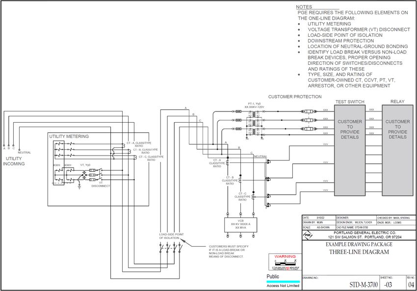
About This Package
About This Package
This Medium Voltage Example Drawing Package provides customers who are building medium voltage services with examples of the
information that PGE needs to see from them. By modeling their submittal on this these examples, customers can speed up the review and
approval of their project.
Individual drawings or pages do not represent the complete requirements for service, and they should not be cited out of their context.
References to any code—including (but not limited to) the National Electrical Code, National Electrical Safety Code, or Oregon Electrical
Specialty Code—always refers to the most recent edition of that code.
We strongly recommend that you consult PGE to discuss any questions you have concerning your service. PGE has an extensive review
process and recommends that customers not purchase gear until PGE has reviewed the design documentation, one-line diagram, and other
documentation, and approves the meter gear in full.
Required Elements for a Customer Drawing Package
PGE requires the drawings listed in this table to evaluate a customer request for new or upgraded service. The table lists the required content
for each drawing.
IMPORTANT: Manufacturer specifications should be submitted separately. PGE does not want 300-page drawing packages.
Name of Drawing Required Contents
Location of switchboard.
Working clearances.
Site Plan Exterior Switchboard
PGE vehicle access route.
Legend that includes units of measure and symbol definitions.
Utility metering.
Load-side point of isolation.
Downstream protection.
Egress route(s) to the exterior of the building.
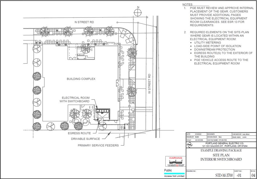
Site Plan Interior Switchboard
Legend that includes units of measure and symbol definitions.
PGE vehicle access route to electrical equipment room.
Note: Customers must provide additional pages showing electrical equipment room clearances. See Section 13 of
PGE’s Electric Service Requirements book for requirements.
Table continues on next page
Medium-Voltage 4
Example Drawing Package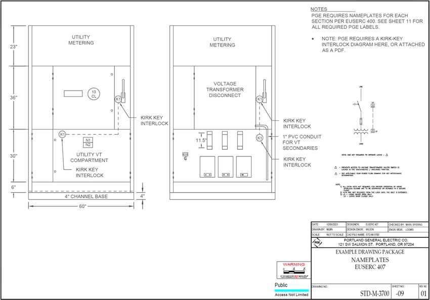
About This Package
Name of Drawing Required Contents
Utility metering (billing and net meters, as applicable).
Voltage transformer (VT) disconnect.
Load-side point of isolation.
First protective device downstream from the point of interconnection.
One-Line Diagram First point of a visual open and ground downstream of the point of interconnection.
Identification of loadbreak and non-loadbreak devices, proper opening direction of switches/disconnects, and ratings
of these.
Note: PGE requires the settings for the first protective device downstream from the point of interconnection at least
16 weeks before energization.
Utility metering.
Voltage transformer (VT) disconnect.
Load-side point of isolation.
Three-Line Diagram Downstream protection.
Location of neutral-ground bonding.
Identification of loadbreak and non-loadbreak devices, proper opening direction of switches/disconnects, and rating.
Type, size, and rating of each customer-owned CT, CCVT, PT, VT, arrestor, or other equipment.
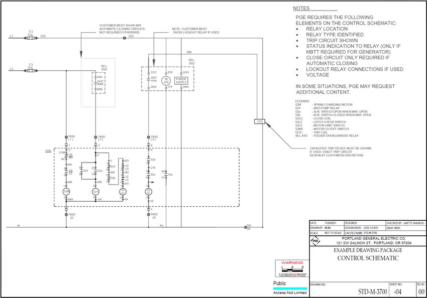
Relay location.
Relay type identified.
Trip circuit shown.
Status indication to relay (only if MBTT required for Generation).
Control Schematic
Close circuit (only if automatic closing is present).
Lockout relay connections (if used).
Voltage.
Capacitive trip device must be shown (if used).
Identify conformance to EUSERC drawing(s).
NEMA rating.
Rated voltage.
Front View Layout Rated current.
or Basic insulation level (BIL) rating.
Back-View Layout Short-circuit current rating (SCR).
Phase designation (3-phase) and rotation.
Wire designation (4-wire).
Dimensions of cabinet and dimensions within internal components, with units of measure listed.
Table continues on next page
Medium-Voltage 5
Example Drawing PackageAbout This Package
Name of Drawing Required Contents
Utility pull section.
Utility metering.
Load-line disconnect.
Top View of Gear Width measurements with units of measure.
NEMA 3R doors indicated.
Access doors open 90 degrees minimum.
Working clearances.
Key measurements to termination points including neutral (EUSERC 418 for 12.47 kV only).
Cabinet depth and working clearance depth.
Termination Section
Phase/phase and phase/ground bus bar separation.
Side and Front Views
Ground studs.
Dimensions of cabinet and internal components.
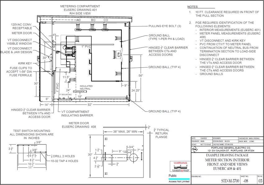
Interior measurements (EUSERC 401).
Meter panel measurements (EUSERC 408).
VT disconnect and Kirk key.
Meter Section Interior PVC from CT/VT to meter panel.
Front and Side Views Continuation of neutral bus from termination section to load-side disconnect.
Hinged clear barrier between the CTs and access doors.
Hinged clear barrier between the VTs and access doors.
Ground balls and studs.
CT mounting plate and clearance dimensions.
CT and VT Mounting Details VT Unistrut mounting and clearance dimensions.
NEMA hole pattern at CT ends. Include hole size and number of holes.
Nameplates Nameplates for each section in accordance with EUSERC 400.
Customer circuit breaker.
Protection relay.
Potential transformer (PT) for customer-owned relay.
Line-side disconnect (if provided).
Bill of Materials VT disconnect switch.
Load-side point of isolation.
Relay potential transformer.
Kirk keys.
PDF copy of the Kirk key interlock diagram.
Table continues on next page
Medium-Voltage 6
Example Drawing PackageAbout This Package
Name of Drawing Required Contents
PGE requires mock-ups of these required labels:
Basic one-line in phenolic across the front of the switchboard.
Utility service termination compartment.
Voltage label.
Voltage phase signs.
Utility line-side disconnect (if present).
Labels
Utility CT compartment.
Utility VT compartment.
Utility VT fuse compartment.
Utility metering compartment.
Utility load-side point of isolation.
Additional labels may be required.
Formatting and Submitting Electronic Files
Follow these rules when preparing your drawing package and submitting it to PGE:
Provide computer-aided drafting (CAD) files with civil engineering drawings of the site plan and profile. PGE accepts AutoCAD 2013 or
greater.
PGE will use your files in the original survey coordinate system or datum; please specify this on the drawing.
Updates to these files are requested at milestones in the project.
Include the same layers in the CAD files as are shown on the site plan and profile hard copy. The minimum layers needed are:
Survey control points. Curbs.
Existing and future street right of way. Sidewalks.
Lot lines. Centerlines of streets and roadways.
Lot numbers. Easements.
Street names. Stationing.
Building footprints. Existing electrical facility locations.
Make sure that your data meets these requirements:
If survey control points are not available in CAD format, PGE software will accept these points in text or Excel file format.
If you use nonstandard file and layer naming conventions, provide guidelines for reference.
If your data contains attachments (such as aerial imagery), either provide the attachments or delete the files from your reference
before submittal.
If you send multiple files, provide a description of what is included in each file.
Manufacturer specifications should not be included in the drawing package. They must be submitted separately.
Medium-Voltage 7
Example Drawing PackageAbout This Package
Submit your files via email. Zipped files are acceptable, but executable (*.exe) files are not.
Note: Contact your PGE Project Manager for approved file transfer methods if your files are too large to transfer using e-mail.
Updates To a Drawing Package
PGE needs to be able to easily see what has changed in your drawing package. If you send a file that is 90% complete and later send a
second file that is 93% complete, it is critical that you let PGE know what was changed in the second file.
In your email that accompanies the package, itemize all data that has changed.
In the drawing, indicate where revision has changed using the cloud method, or place revision numbers next to affected portions of the
drawing.
IMPORTANT: Non-itemized changes may result in inaccurate reviews or approval of gear, which upon discovery may require re-review and different
gear at the customer’s expense.
Medium-Voltage 8
Example Drawing PackageExample Drawings Example Drawings Site Plan Exterior Switchboard Medium-Voltage 9 Example Drawing Package
Example Drawings

Site Plan Interior Switchboard

 Medium-Voltage                               10
 Example Drawing Package
Example Drawings

One-Line Diagram

 Medium-Voltage                         11
 Example Drawing Package
Example Drawings

Three-Line Diagram

 Medium-Voltage                         12
 Example Drawing Package
Example Drawings

Control Schematic

 Medium-Voltage                         13
 Example Drawing Package
Example Drawings

Front View Layout or Back View Layout

 Medium-Voltage                                      14
 Example Drawing Package
Example Drawings

Top View of Gear

 Medium-Voltage                         15
 Example Drawing Package
Example Drawings

Termination Section Side and Front Views

 Medium-Voltage                                         16
 Example Drawing Package
Example Drawings

Meter Section Interior Front and Side Views

 Medium-Voltage                                            17
 Example Drawing Package
Example Drawings

CT and VT Mounting Details

 Medium-Voltage                           18
 Example Drawing Package
Example Drawings

Nameplates

 Medium-Voltage                         19
 Example Drawing Package
Example Drawings

Bill of Materials

  Medium-Voltage                         20
  Example Drawing Package
Labels

Labels

 Medium-Voltage               21
 Example Drawing Package
Labels

Medium-Voltage               22
Example Drawing Package
You can also read