Maxi 3200 - Operating instruction - Coin box - Holtkamp Electronics GmbH
←
→
Page content transcription
If your browser does not render page correctly, please read the page content below
Maxi 3200
     Coin box

Operating instruction
Holtkamp Electronics MAXI 3200 					                                         techn. stand 12.2020                                                                   4153_01.2021

                                                                                                                    S ü d s t r a ß e 4 0 / D- 4 9 0 8 4 O s n a b r ü c k
                                                                                                                    info@holtkamp.de / www.holtkamp.de

                      EU-Konformitätserklärung / European Union conformity explanation

   Für das nachfolgend bezeichnete Erzeugnis / For the following designated product

                                                          Zeitsteuerung vom Typ / Time control type

                                                                                MAXI 3200
   wird hiermit bestätigt, dass die Bauart, in der von uns in Verkehr gebrachten Ausführung, den unten genannten Normen
   entspricht.
   It is hereby confirmed, that the construction in that execution brought by us in traffic corresponds to the standards specified
   down.

   Diese Erklärung gilt für alle Geräte, die nach den beiliegenden technischen Unterlagen, welche Bestandteile dieser Erklärung
   sind, hergestellt werden.
   This explanation applies to all devices, after the enclosed technical documents, which are components of this explanation,
   are manufactured.

   Einschlägige EG-Richtlinien / Relevant EC guidelines
   RoHS-Richtlinie 2011/65/EU / RoHS Directive 2011/65/EU

   1. 2014/35/EU (Niederspannungsrichtlinie)
      2014/35/EU (low-voltage guideline)

   2. 2014/30/EU (EMV-Richtlinie)
      2014/30/EU (EMC guideline)

   Angewendete harmonisierte Normen:
   Applied harmonized standards:

        EN 60335-1 von 08/2020 (Sicherheit)
        EN 60335-1 from 08/2020 (security)
        EN 61000-6-3 von 09/2011 (Emissionen)
        EN 61000-6-3 from 09/2011 (emissions)
        EN 55032 Kl. B von 02/2016 (Emissionen)
        EN 55032 Kl. B from 02/2016 (emissions)
        EN 61000-3, Teil 2 + 3 von 12/2019 und 07/2020 (Emissionen)
        EN 61000-3, part 2 + 3 from 12/2019 and 07/2020 (emissions)
        EN 61000-6-2 von 11/2019 (Immunität)
        EN 61000-6-2 from 11/2019 (immunity)

   Diese Erklärung ist bindend für den Hersteller
   This declaration is binding on the manufacturer

   Holtkamp Electronics GmbH
   Südstraße 40 in 49084 Osnabrück
   abgegeben durch:
   Signature:
   M. Hashemizadeh (EMV-Beauftragter)

   ..........................................
   Osnabrück, den 05.02.2021

   Telefon: +49 541 97120-0, Fax: +49 541 97120-40
   Geschäftsführung: Magnus Michael; Sitz der Gesellschaft: Osnabrück, AG Osnabrück HRB 213567
   Banken: Deutsche Bank Osnabrück, IBAN: DE28 2657 0090 0039 5251 00; SWIFT/BIC: DEUTDE3B265

   Die Lieferung erfolgt zu unseren Allgemeinen Verkaufs- und Lieferbedingungen mit Stand April 2020. Es gelten unsere Einkaufsbedingungen mit Stand Januar 2020.

                                                                                           -2-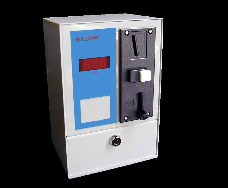
Holtkamp Electronics MAXI 3200 					                                                  techn. stand 12.2020                                                                             4153_01.2021

                                                                                                Inhalt

1    Legal information.......................................................................................................................................................................... 4
2    Warranty		           ................................................................................................................................................................................. 4
3    Safety notices............................................................................................................................................................................... 4
4    Notes on cleaning and maintenance.......................................................................................................................................... 4
     4.1        Change battery ................................................................................................................................................................... 4
5    Spezific data ................................................................................................................................................................................. 4
6    General data ................................................................................................................................................................................. 5
7    Illustration         ................................................................................................................................................................................. 5
     7.1		      Illustration of device............................................................................................................................................................. 5
     7.2		      Illustration of electronic........................................................................................................................................................ 6
8    Installation         ................................................................................................................................................................................. 6
     8.1		Installation notes................................................................................................................................................................. 6
     8.2		Mounting notes.................................................................................................................................................................... 6
     8.3        Mounting instructions.......................................................................................................................................................... 7
     8.4        Electrical connection........................................................................................................................................................... 7
     8.5        Operating the first time........................................................................................................................................................ 8
9    Specifications............................................................................................................................................................................... 8
10 Programming................................................................................................................................................................................ 8
     10.1       Explanation the Programming............................................................................................................................................. 8
           10.1.1 Special function (time meter - DIP 1.............................................................................................................................. 9
           10.1.2 Adjustment pre-begin time (DIP 2)................................................................................................................................ 9
           10.1.3 Adjustment main time (DIP 3)........................................................................................................................................ 9
11 Bookkeeping-statistic menu...................................................................................................................................................... 10
     11.1       Inquiry schema - delete the statistics................................................................................................................................ 10
     11.2       Explanation of the bookkeeping-statistic menu................................................................................................................. 11
12 Not programmable special equipments................................................................................................................................... 11
     12.1       Contactor 2 x 20 A............................................................................................................................................................. 11
     12.2      Connection for time stop................................................................................................................................................... 11
     12.3      Current-dependent time stop............................................................................................................................................. 11
     12.4       Potential free relay contact................................................................................................................................................ 11
     12.5      Current-dependent time stop............................................................................................................................................. 12
     12.6       Short-time button............................................................................................................................................................... 12
     12.7       Delete entrance................................................................................................................................................................. 12
     12.8       Coin barrier........................................................................................................................................................................ 12
13 Malfunctions ............................................................................................................................................................................. 12
     13.1       General errors................................................................................................................................................................... 12
     13.2       Special errors .................................................................................................................................................................. 13
Index				............................................................................................................................................................................... 14

Important: For safe and proper use, read the instructions for use and further product-related documents carefully and keep
it for later use!

For errors, technical errors, printing errors and incompleteness, we assume no liability.

                                                                                                -3-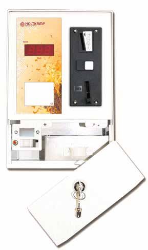
Holtkamp Electronics MAXI 3200 techn. stand 12.2020 4153_01.2021
1 Legal information 2 Warranty
All rights reserved. No part of this manual may not be reproduced The function of the device is guaranteed for 12 months from the
or copied in any form without permission of Holtkamp Electronics date of sale (invoice date counts). The warranty is limited exclu-
GmbH. The rights for contained software in control and memory sively to technical defects of the device, further claims can not
blocks are exclusively from the manufacturer. The reading and be recognized.
copying of the program content is strictly prohibited. Furthermore, our General Terms and Conditions apply, as of April
The Holtkamp Electronics GmbH is not liable to the purchaser 2020 - see also homepage: www.holtkamp.de. Any liability expi-
of this product or third parties for damages, losses, costs or ex- res in case of tampering with the device.
penses caused by the buyer or any third party due to accident,
misuse or unauthorized alterations, repairs or improvements.
The Holtkamp Electronics GmbH shall remain liable for any loss,
costs, disruptions or consequential damages that result from the
use of the control.
The technical data are up to date. Misprints, errors and modi-
fications excepted. Older manuals are no longer valid with the
publication of this manual.
3 Safety notices
The coin boxes are built according to the prior art and the reco- This is guaranteed only for original spare parts. Do observe the
gnized safety rules. in the user manual specified or prescribed deadlines for recurring
Nevertheless, its use threats to life and limb of the user or third maintenance intervals! Do provide for the safe and environmen-
parties, or cause damage to the device or other equipment du- tally friendly disposal of plastic parts and electronic replacement
ring use. Use the device only in perfect condition, and intended, parts!
safety and the risk of danger, in compliance with the instruction The manufacturer is not liable for damage caused by improper
manual! Do immediately eliminate particular disorders, which use. The user bears the risk. Intended use also includes com-
may affect safety! Always keep the operating instructions directly pliance with the operating instructions and compliance with the
to the coin box! Note, in addition to the user guide, the generally inspection and maintenance conditions
applicable legal and other mandatory regulations relevant to ac-
cident prevention and environmental protection! ATTENTION:
Perform no changes and/or modifications to the coin box without The installation must be performed by authorized
approval of the manufacturer! Spare parts must meet the requi- personnel! Therefore, make sure that the installation
rements specified by the manufacturer. is carried out by an electronics specialist! Since this
is a stationary device with main-side fixed connecti-
on, a circuit breaker must be installed on the instal-
lation side!
4 Notes on cleaning and maintenance
The device is mostly maintenance-free. By poor coin acceptan- 4.1 Change battery
ce, the coin runway of the mechanic single coin tester can be
cleaned with a damp cloth or brush to remove any dust or de- The MAXI used for the memory statistics a battery Typ CR2032,
posits. The metal casing can be cleaned with a damp cloth or this should be changed all 2 years. If this not happened, the sta-
a cleaning agent which can be dissolved in water. Do not use tistics can be lost.
under any circumstances, thinners, petrol, acetone or scouring How to change the battery:
cleaning agents.
The battery-changing can only be done by authorised
and qualified electricians!
Remove the voltage from the MAXI. Remove the front plate. Bra-
ze out the old battery and take a new battery. Take care, that you
braze the new battery in the right way! It is important to connect
the device after the changing for a short time. If this not hap-
pened, the new battery can be empty in a few days! If the DIP-
points are flashing go over the bookkeeping-statistic menu to
delete this error message.
5 Spezific data
Write down the following data:
Key number (imprint on the key)
Number of identification from device (see bookkeeping-statistic menu)
Commission (name customer)
Trader (via which the device was purchased)
-4-Holtkamp Electronics MAXI 3200 techn. stand 12.2020 4153_01.2021
6 General data
Casing material Galvanised steel plate 1,5 mm
Casing color Powder-coated white RAL 9016
Color design foil yellow orange
Design foil from customer on request
Dimensions h 255 mm x w 170 mm x d 135 mm
Weight ca. 4,0 kg
Temperature range 0° to 50°C
Voltage maintenance 230 V or 24 V, 50 / 60 Hz
Switched power 6,3 A by cos phi = 1; 230 V / 24 V
Power absorption 3,3 VA
Protection class I by 230 V~ or III by 24 V
Protection type IP20
Fuse circuit board SI1 50 mA T
Attention: Fuses may only be replaced with the same
value!
We reserve the right to technical changes in the production and technical developments.
7 Illustration
7.1 Illustration of device
1
12 2
3
11
4
5
10
9
6
1 Housing-lower part
2 Coin acceptor 8
3 Coin slot
4 Reject button for coins*
5 Coin reject 7
6 Coin box
7 Removel of coins
8 Lock
9 Button for accounting-statistics menu
10 Front plate
11 LED-Display
12 Design foin (standard)
* (Special equipment) You can used the rejcet button for coins as door opener.
-5-Holtkamp Electronics MAXI 3200 techn. stand 12.2020 4153_01.2021
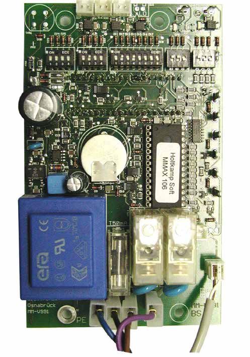
7.2 Illustration of electronic
11 12 13 14 15
10 1
1 DIP switch for price settings
2 Connection for coin barrier
3 Connection for mechanical hour
counter
4 Connection for mechanical
impulse counter 2
5 Connection for free use
6 Connection for account statistic
menu button
7 Elektrical connection
8 Fuse circuit board 3
9 Battery 3V CR 2032
10 DIP switch for time settings
11 Conntection for short time button 9
12 Remote start
13 Connection for time stop 4
14 Delete entrance
15 Connection for coin acceptor
Special equipment
5
6
8
7
Circuit board MM-V99-1 230 V~
8 Installation
8.1 Installation notes 8.2 Mounting notes
Through micro-electronics, the "MAXI 3200" reaches a high reli- ● The MAXI 3200 were designed for the montage on the wall
ability in the daily use. This can only be reached if the installation and for partial into the wall.
takes place expertly. Heed with the installation necessarily, … ● The coin timer must be well fast. For this, please use the
● She must after VDE- rule and from electro experts is en attachments of rear from casing.
forced. ● The device is cabled by means of threaded metric threads
● With counters with 230V is necessary the connection of the on the bottom or rear.
protection-leader and with counters with 24V is required the ● The MAXI 3200 corresponds to the protection-type IP20
protection-ladder as function-earth. and can be used only in dry rooms/areas..
● The floor must antistatic and conductive, that not statically ● The MAXI 3200 must be installed vertically and horizontally
loads. exactly. The inclination should not exceed 2° in any direction.
-6-Holtkamp Electronics MAXI 3200 techn. stand 12.2020 4153_01.2021
8.3 Mounting instructions
● Disconnect the power supply by moving the corresponding ● Drill the holes and insert suitable dowels. Make
disconnector, with fuse or even by triggering of the protecti- the electrical connection through the holes in the rear-
ve switch. wall or from below. Metric thread (M20) fittings are required
● Unlock the lock of coin acceptance and remove the coin when wiring from below.
flap. ● Then fix the housing with suitable screws. Now restore the
● Loosen the two front panel screws and lift the front panel. electrical connections. Now replace the front panel and
screw it in place.Insert the coin box, then place the removel
● Disconnect the electrical connectors and remove the front
panel completely. of coins, fold it and lock it.
● Using a spirit level, align the bottom of the housing horizon-
tally and vertically and mark the three mounting holes.
8.4 Electrical connection Connection 230V Remote start (potential free)
The electrical connection can only be carried out by the local
VDE regulations. With a permanent connection, an all pole mains
separator with at least 3 mm contact gap must be used. Before
starting the electric circuit must be disconnected. Shut down the
mains input by activating the separator switch, remove the fuse
or release the main safety fuse. Mains and low voltage cable
must be spaced apart. Low voltage cables should be generally
spaced as screened cables.
After the electrical connection the MAXI can completed.
Mains and low voltage cables must be laid separately from each
other. Low voltage cables should be laid generally as shielded
cables. After the electrical connection has been made, the MAXI
can be completed again.
Lead blinding
ATTENTION: to PE clamp!
The installation must be performed by authorized
personnel! Therefore, make sure that the installation
is carried out by an electronics specialist! Since this
is a stationary device with main-side fixed connecti-
on, a circuit breaker must be installed on the instal-
lation side!
Connection 230V~ Connection 24V~
MAXI 3200 MAXI 3200
LN LH N L LN LH U0 U1
green-yellow
green-yellow
Earth wire
Earth wire
brown
brown
violet
violet
black
black
blue
blue
L1 L2 PE N L3 L1 L2 PE U0 U1
230V~ Remote start
24V~ Remote start
-7-Holtkamp Electronics MAXI 3200 techn. stand 12.2020 4153_01.2021
8.5 Operating the first time
If the MAXI is installed can through switches on the stream. The A manipulation is recognized deletes the MAXI the coins thrown
time-counter is now operational and can become program. Please in until then and breaks off the use. The manipulation was store
test the programming through a test-sprint. After this test, you in accounting statistic menu, as mistake. If a mistake happens,
should delete the readings to get about a correct bill. The MAXI the MAXI blinks. Through call up the accounting statistic menu
has protection a sabotage the were active if the contact of the you can finish the blink.
coin acceptor is closed longer than 0,2 seconds.
9 Specifications
MAXI 3200
controls 1 device (e.g. sun bed)
Mechanical single coin acceptor
Main time per insert (1 min. – 9 h 59 min.)
LED display 3 digits (time units)
Programming by DIP swiches
Time memory
Electronic operating hour counter
Electronic impulse counter
Potential free relay contact
key switch for free use
Short time impulse for washing machine door opener
Contactor 20 x 2 A
Connection for time stop
Current-dependent time stop
Coin barrier for mechanical coin tester
Customized design foil on request
Standard Special equipment Production-technical changes and further development reserved.
10 Programming
10.1 Explanation the Programming
The MAXI offers the possibility, to make the adjustments of the
values over DIP switches (see illustration).
DIP 1 DIP 2 DIP 3 DIP 4 DIP 5
Special- Pre-run Main time Run-out Price
function time time
-8-Holtkamp Electronics MAXI 3200 techn. stand 12.2020 4153_01.2021
10.1.1 Special function (time meter - DIP 1
DIP 1: Switch 1 "ON" = Memory is activated during main Switch 2 "ON" = hours are activated
time Switch 2 "OFF" = minutes are activated
Switch "OFF" = Memory is deactivated during
main time Switch 3 "ON" = seconds are activated
Switch 3 "OFF" = minutes are activated
Iftimeyouduring
put the DIP switch on "ON ", then you can still buy
the time before start. Switch 4 "ON" = HQL is activated
Switch 4 "OFF" = HQL is activated
The time meter can be adjusted in minutes or seconds.
The attitudes can you take from the following example: Iftimeshould be assumed no money during the after cooling
of the tanning bed, you must set the DIP switch of
"ON ".
10.1.2 Adjustment pre-begin time (DIP 2)
The pre-begin time is the time from payment on MAXI to the start (x) = The remote button is not required.
of the device. It is adjustable from 0-7 minutes in minute steps. The main time begins with paying.
Remote start
The remote start offers the possibility, to break off the pre-begin ON ON
time and start the main time over external potentialfree button. OFF OFF
1 2 3 4 1 2 3 4
Minutes: 1 2 4 pre-begin off (X)
Example: 2 minutes pre-begin time ON
OFF
1 2 3 4
Should the main time running after the payment on the timer th-
rought pressing the remote button only, you must adjusted the ON
pre-begin time on "0". That means, all switches from DIP 2 must
adjusted upwards on "OFF". OFF
1 2 3 4
The bought main time is indicated flashing during the
pre-begin time.
10.1.3 Adjustment main time (DIP 3)
The main time is the operating time of the connected device,
which can be bought with coins. It can be adjusted until maximal
225 minutes for each payment. Buying the main time more than
ones is possible, and there happens an add up to maximal 25
main times. The adjustment of the main times is doing over the
showed 8 DIP switches.
Configuration:
The DIP switches are binary coded, this means, every DIP-
switch has his own value.
The main time is programmed in minute-steps. How to program
the seconds: ON
OFF
1 2 3 4 5 6 7 8
Minutes: 1 2 4 8 16 32 64 128
-9-Holtkamp Electronics MAXI 3200 techn. stand 12.2020 4153_01.2021
To adjust a main time, the DIP switches must be activated - on
"ON". With combination of the DIP switches, which adjusted
upwards on "ON", you can adjusted every main time from 1 mi-
nute to 255 minutes.
ON
Example: 10 minutes main time
When the main time is running, the point in the display is flashing OFF
1 2 3 4 5 6 7 8
9.59. flashing point
Minutes: 1 2 4 8 16 32 64 128
Notice, that you can get faults, if all DIP switches of
this block are downwards. At least minimum one DIP
switch via block must be upwards (on "ON").
10.1.4 Adjustment run-out time (DIP 4)
The run-out time is the additional time of the fan of the sun bed, ON Example: 3 minutes run-out time
after the run out main time (after cooling). The run-out time relay Is activated the run-out time, in the
remains on longer the adjusted run-out time than the main time. OFF display is flashing “0”.
It is adjustable from 1 to 7 minutes in minute steps. 1 2 3
Minutes: 1 2 4
10.1.5 Ádjustment price (DIP 5)
Here you choose, how much coins/money you have to throw in to
ON
buy the configured main time once. You can do this up to seven
coins. The DIP switches are binary coded as you have to coded OFF
the main time. This means: for every DIP switch you have an 1 2 3
extra value (see picture). Coins: 1 2 4
To configure, how much coins you have to throw for buying the
Example: 5 coins
main time, the DIP switches have to activated. This happens, if ON
you push the DIP-switches up to "ON".
Now you are able to switch the needed combinations between 1 OFF
1 2 3
and 7 coins.
Coins: 1 2 4
Notice, that you can get faults, if all DIP switches are
downwards. At least minimum one DIP switch via block
must be upwards (on "ON").
11 Bookkeeping-statistic menu Open: Statistic
11.1 Inquiry schema - delete the statistics .1. Impulse counter quantity of coins
You came into the statistic menu, if you remove the coin removal .2. Operation hours counter full hours
and push the red button. That is on the upper left side in the coin-
insert-box. Pushing this button, activated the following statistics. .3. Operation hours counter full minutes
Every point from the statistic has own numbers, instead fort he .4. Impulse counter service activations
meaning words. You can see opposite, what the numbers mean.
Statistic point and the meaning are changing after choosing. .5. Impulse counter quantity of counter deletes
Some of them can be cancelled – in this case the menu points
are grey. .6. Activations service runs
Deleting one of the statistic points is possible, if you throw a coin
into the coin tester during this statistic is. shown. The menu is au- .7. Report or error count
tomatically gone, if you push the red button after the menu point
10 again or if you do not press the button between 30 seconds. .8. Internal checksum
.9. Electronically number of identification
.10. Number of program identification
0 Standard operating condition
- 10 -Holtkamp Electronics MAXI 3200 techn. stand 12.2020 4153_01.2021
11.2 Explanation of the bookkeeping-statistic
menu
● Impulse counter quantity of coins. 1. ● Impulse counter quantity of counter deletes . 5.
Counter for quantity of inserted tokens/coins. The counter Counter for the counter deletes. This counter is not to de-
counted maximal up to 999 and started than again with "0". lete. The counter counts maximal up to 999 and restarted
If the counted over, you find under Point 7 of the sta- from "0".
tistic menu the fault-code 10. With insert of a coin during the ● Activations service runs . 6.
counter capacity is shown, you can delete this to "0". After insert a coin the main relay is starting. Only the impul-
● Operation hours counter full hours . 2. se counter for the service activations point 4 will be depen-
Counter for the quantity of full operating hours. If this coun- ding on this. The service-run can be stopped, if you go back
ter will be deleted, automatically the counter "Operation in the bookkeeping-statistic menu and you reach the nor-
hours counter full minutes" also is delete. The counter mal modus.
counts maximal up to 999 and started than again with "0 ". ● Report or error count . 7.
If he counted over, you find under Point 7 of the statistic If this special fault happens, there will be a fault code lay
menu the fault-code 11. With insert of a coin during the down under point 9.2 "special faults" explained. With insert
counter capacity is shown, you can delete this to "0". a coin during the counter capacity is shown, you can delete
● Operation hours counter full minutes . 3. this to "0".
Counter for the quantity of full minutes. If this counter will ● Internal checksum . 8.
be deleted, automatically the counter "Operation hours This internal checksum is only for the manufacturer and not
counter full hours" also is delete. The counter counts ma- to be deleted.
ximal up to 59 and started than again with "0 ". If he counted ● Electronically number of identification . 9.
over, you find under Point 7 of the statistic menu the fault- If you ask for technical help, the manufacturer can make
code 11. an exactly electronic analysis. Not to delete! Please write
● Impulse counter service activations . 4. this number down on page 2!
Counter for the quantity of full service hours. The counter ● Number of program identification . 10.
counts maximal up to 999 and started than again with "0 ". Included the version from the software. Not to delete! Plea-
If he counted over, you find under Point 7 of the statistic se write this number down on page 2!
menu the fault-code 12. With insert a coin during the coun-
ter capacity is shown, you can delete this to "0"
12 Not programmable special equipments
12.1 Contactor 2 x 20 A 12.2 Connection for time stop
The contactor offers the possibility, to increase the switching po- The extra connection for time stop offers the possibility, to inter-
wer of the MAXI. If you have ordered your MAXI with a contactor, rupt the main time count-down with an external switch (e.g. flow
it will be installed on the SB frame inside on the rear wall of the sensor). If your MAXI has been ordered with an extra connection
casing. for time stop, you will find on the SB frame, on the inside rear
wall of the casing a 2-pole screw-terminal to connect an external
switch (potential free closing contact). This special equipment
can not be ordered with the special equipments cleaning button
or short time impulse for washing machine door opener.
12.3 Current-dependent time stop 12.4 Potential free relay contact
The current-dependent time stop offers the possibility, to dis- If you have ordered your MAXI with potential free relay contacts,
connect the main time depended on the power input of the the closing contact of the main relay or the run-out relay, will be
connected device. If the power input is e. g. under 40, 80 or 100 voltage free on the screw terminals. These terminals are on the
mA (as ordered), then the main time count-down will be inter- SB frame, inside the rear wall of the casing.
rupted.
- 11 -Holtkamp Electronics MAXI 3200 techn. stand 12.2020 4153_01.2021
12.5 Current-dependent time stop
Time electronic
The current-dependent time stop offers the possibility of interrupt-
ing the main time sequence depending on the current consump- Coin acceptor
tion of the connected device. If the current consumption is e.g. Time stop
Below 40, 80 or 100 mA or 130 mA (according to your order), the electronics
main timeout will be interrupted.
Contactor 2 x 20 A
Mainrelay A1 PE N L (Special equipment)
12.6 Short-time button 12.7 Delete entrance
The short-time button offers the possibility for example by using The delete-entrance offers the possibility bought time or rest
the coin reset-button to open the washing machine door to turn time to delete with the potential free contact. You find this extra
the connection appliance on for 30 seconds. After using this connection on the SB frame on the inside rear wall of the casing.
short-time button the functions is not useable for 3 minutes.
12.8 Coin barrier
The coin barrier offers the possibility to block the coins, e.g. if the
supply voltage is disconnected or the MAXI is off.
If should not to be possible the insert of coins during the main
and run-out time, you must set the dip switch 1 and 4 at DIP1
(special functions) on the PCB on "ON" upward additionally to
the coin barrier.
13 Malfunctions
13.1 General errors
If your MAXI does not behave as you would like, try to help your- Electricity installations make leave only by an electrical
self with the following list. If you cannot repair the problem your- specialist!
self, then the trader is, of course, there to help.
Defect Possible causes Remedy
Fuse defect Change the fuse
The display is dark
No operating voltage Test the mains voltage
The display shows irregular symbols Malfunction of the µ-processor interrupt the mains voltage for approx. 10 seconds
The MAXI functioned, but the attached MAXI wrongly installs Check the connection
device does not functioned. Attached device is defect Check the attached device
The timer functions (prices, Times etc.) Wrong programming controls and correct programming
deviate from the desired function. DIP switches stand wrongly correct DIP switches
DIP points flashing all 5 seconds Special error Read point „Special errors“
DIP points flashing all the time Not allowed function Redress the external malfunction
- 12 -Holtkamp Electronics MAXI 3200 techn. stand 12.2020 4153_01.2021
13.2 Special errors
4 points in the display of the MAXI 3200 are flashing and this In the below list you can see, what is behind the code. If you go to
means, there is a special error. Under point 7 in the book- the bookkeeping-statistics menu the flashing is automatically off.
keeping-statistics menu you can read out the error number.
Error code Possible causes Remedy
1 Memory delete, battery empty Change the battery
2 Memory defect Change the electronic board
3 Memory defect Change the electronic board
4 Memory defect Change the electronic board
5 Memory defect Change the electronic board
Coin switch-sabotage
Clean up the coin tester and make sure, that there can not be
6 Micro-switch of the coin tester are closed to
any sabotage
long– Sabotage is possibility
Safety loop during impulse operation has broken
7 Check the cable
Error is possible only during decrement function
Impulse counter has an overflow
10 Delete impulse counter
Maximum from 999 is reached
Operating hours counter has an overflow
11 Delete operating hours counter
Maximum from 999 is reached
Service activations counter has an overflow
12 Delete service activations counter
Maximum from 999 is reached.
Memory delete, because irregular counter rea-
15 Register and delete the error indicator
dings are noticed
Not defined switching state on the board - ser- It is possible, that the connection is wrong.
16
vice needed Please ask for technical support
Electricity installations make leave only by an electrical specialist!
- 13 -Holtkamp Electronics MAXI 3200 techn. stand 12.2020 4153_01.2021
Index
A S
Adjustment main time 9 Safety notices 4
Adjustment pre-begin time 9 Short-time button 12
Ádjustment price 10 Special equipments, not programmable 11
Adjustment run-out time 10 Special errors 13
Special function 9
B Specifications 8
Battery change 4 Spezific data 4
Bookkeeping-statistic menu 10
T
C Time stop 11
Change battery 4
W
Cleaning 4
Coin barrier 12 Warranty 4
Connection for time stop 11
Contactor 2 x 20 A 11
Current-dependent time stop 11, 12
D
Delete entrance 12
Delete the statistics 10
E
Electrical connection 7
Errors 12, 13
Explanation of the bookkeeping-statistic menu 11
Explanation the Programming 8
G
General data 5
General errors 12
I
Illustration of device 5
Illustration of electronic 6
Inquiry schema 10
Installation notes 6
L
Legal information 4
M
Maintenance 4
Malfunctions 12
Mounting instructions 7
Mounting notes 6
N
Not programmable special equipments 11
O
Operating the first time 8
P
Potential free relay contact 11
Programming 8
- 14 -Holtkamp Electronics MAXI 3200 techn. stand 12.2020 4153_01.2021
- 15 -For technical information during our business hours:
Monday - Thursday 8.00 a.m. - 16.00 p.m. and Friday 8.00 a.m. - 13.00 p.m. choose:
+49 541 97120-0
or visit our homepage:
www.holtkamp.de
Technical Stand 12.2020 / We reserve the right to technical changes in the production and technical developments.
4153_01.2021
Südstraße 40, D-49084 Osnabrück
Phone: +49 541 97120-0
info@holtkamp.deYou can also read