Low-Voltage DMX Control - OPERATION GUIDE - 580 Mayer Street - Building # 7 - Bridgeville, PA 15017 USA - Brightline
←
→
Page content transcription
If your browser does not render page correctly, please read the page content below
Low-Voltage DMX Control
                                                                                              OPERATION GUIDE

580 Mayer Street - Building # 7 - Bridgeville, PA 15017 USA

Phone: 1.412.206.0106               www.brightlines.com
                                                                                                © 2021 Brightline LP All Rights Reserved
                                       Specifications are subject to change without notice.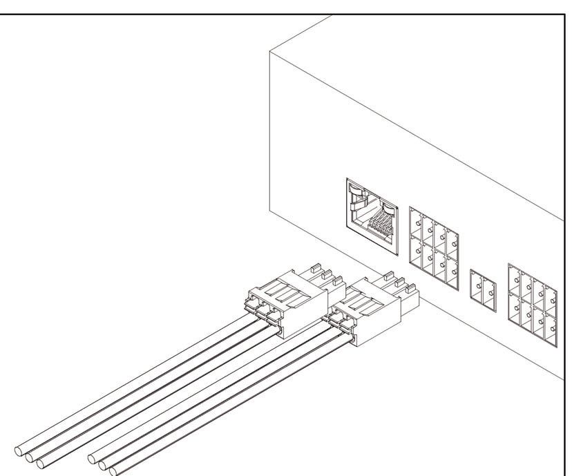
Safety
    •    To prevent fire or shock hazard, do not expose the unit to water or moisture. Brightline fixtures are listed for
         indoor use only.
    •    Do not attempt to dim a non-dim fixture.
    •    A qualified technician should perform service on fixtures. Do not access internal components until the unit
         has been fully powered off.

    Owner’s Record
              The model and serial number of this product can be found on the side of the fixture’s main housing.
              You should note the model number and the serial number in the space provided and retain this
              book for future reference as a permanent record of your purchase.

                Model #:______________________________

                Serial #:______________________________

                Date of Purchase:________________________

    Product Description
    •    Brightline’s low-voltage control system facilitates an easy-to -set-up lighting system for video applications.
         Stand-alone systems are quoted with a DMX console and wall-mounted playback station (CTRL-WS-LV-
         SR516). Utilizing the DMX console, or another device with DMX output, set each module to the desired
         dimming level and record as an individual scene. When using the CTRL-WS-LV-SR516 you can record up to
         16 individual scenes.

    • The 6060 Power Driver ships configured for field operation.

    • If there is more than one 6060 Power Driver within the system, the installer will need to set the DMX starting
    address on the additional 6060 Power Drivers (see page 3).

    • All components necessary for operation of the 6060 Power Driver are included:
            (1) 6060 Power Driver
            (1) IEC power cord
            (16 or 32) Phoenix connectors
            (1) 1-foot RJ45 cable
            (1) 1-foot DMX 5-Pin (M) to RJ45 adaptor

        580 Mayer Street - Building # 7 - Bridgeville, PA 15017 USA

        Phone: 1.412.206.0106               www.brightlines.com
                                                                                                      © 2021 Brightline LP All Rights Reserved
2                                              Specifications are subject to change without notice.
Overview
Operating Mode
Each 6060 Power Driver is configured to the required operating mode. If there is more than one 6060 Power
Driver refer to DMX addressing information below.
A separate 6060 Power Driver is required for each fixture type in the installation. If the device is inadvertently
reset to factory settings, call Tech Support at 1-412-206-0106 ex.113 or email
techservice@brightlines.com for detailed instructions to re-configure the device for use with Brightline
fixtures.
Setup
Locate your 6060 Power Driver in a control cabinet or 19-in rack (rack screws not included).
See the Brightline Low-Voltage System Quick Setup Guide for both DMX and power connection schemes.
See accompanying appendixes for fixture connection details.
Multiple 6060 Power Drivers can be linked with the DMX Thru (LED Sync Thru) jack and the included 1-ft
RJ45 cable.
Configuring DMX Starting Address
All 6060 Power Drivers ship with factory configured settings so that the default DMX starting address is 1.
See below for DMX address requirement for additional devices.
The DMX addresses will always move sequentially across ports 1-8.
To address unit:
Press [ M ] DMX address will appear with the current starting address
Press [ + / - ] to adjust to desired starting address
Press [ M ] to store DMX revised starting address (menu will exit after 5 second of inactivity)
Flex-T Module LST6 BL.16 LVCI LVP2 LVP4
Qty per 6060PD 22 7 8 14 up to 8 up to 4
LV WaƩage 27w 81w 34w 40.5w 27w 27w
Current Seƫng 800ma 800ma 700ma 800/400ma 800ma 800ma
Group Seƫng 3:3L 1:4L 1:4L 2:4L 3:3L 3:3L
DMX Addresses 24 8 8 16 8 8
Fixture Setup InstrucƟons Appx. A Appx. B Appx. C Appx. D Appx. E Appx. F
Note: Each fixture type requires its own 6060 unit.
580 Mayer Street - Building # 7 - Bridgeville, PA 15017 USA
Phone: 1.412.206.0106 www.brightlines.com
© 2021 Brightline LP All Rights Reserved
Specifications are subject to change without notice. 3Overview
Testing Fixtures after Installation
To test that fixtures are receiving power prior to connecting to a DMX controller:
1. Connect all fixtures and devices then power on your 6060 Power Driver.
2. Simultaneously press the [M, +, and –] buttons. DO NOT HOLD.
3. Each port position will turn on for one second sequentially, followed by all fixtures on for
one second. This pattern will repeat twice. (Ex. R, G, B, W, then ALL, repeat).
Connecting a Wall Station
The CTRL-WS-LV-SR516 wall station comes with all necessary parts to integrate into the stand-alone low-
voltage control system. To connect the CTRL-WS-LV-SR516 to the 6060 Power Driver, run the RJ45 to bare
lead cable from the wall station to the DMX IN port on the back of the 6060 Power Driver, or to a DMX gateway
networking device for integration with other controls. (see the Brightline CTRL-WS-LV-SR516 Overview for
wiring instructions at the wall station). Ensure that the wall station is in line between the controller and the
6060 Power Driver for proper operation. See the Brightline CTRL-WS-LV-SR516 Overview for more detail.
EXTERNAL CONNECTIONS
SR-516W
(Rear View) J1
+12V 2
POWER IN
OFF RECALL DMX COM 1
Bank K1
REC A/B
DMX DMX SMART SIMPLE
OUT IN REM REM
1 2 3 4 J2 1 2 3 456 J3 1 2 3 456 7 8 9
5 6 7 8
COM
DMX OUT-
DMX OUT+
COM
DMX IN-
DMX IN+
System Integration
A DMX IN signal is required for integration with non-Brightline provided control systems. A DMX 5-Pin
(M) to RJ45 adaptor is provided by Brightline for convenience. Simply connect the control system to the
DMX IN port. Consult manufacturers’ documentation for setup and integration instructions.
580 Mayer Street - Building # 7 - Bridgeville, PA 15017 USA
Phone: 1.412.206.0106 www.brightlines.com
© 2021 Brightline LP All Rights Reserved
4 Specifications are subject to change without notice.Appendix A
Flex-T Fixtures
Operating Mode
Prior to shipment each 6060 Power Driver is configured
to the required operating mode.
4th Position on Port not used
In the 3:3L operating mode, the first 3 positions for each
port are active and usable. The 4th position on each port
is disabled and inactive to prevent overload. Port
DMX addresses distribute sequentially by active position. 32 3130 29
Looking at the back of the device, addresses read from
right to left, 1-24 (ex. with the 4th position inactive, Position #
position 5 is assigned DMX address 4).
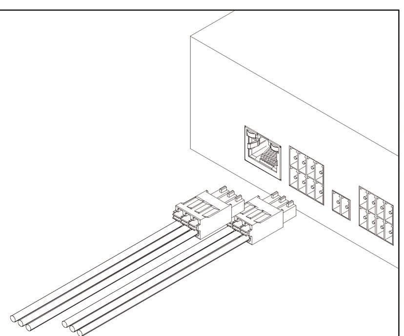
Connecting Fixtures
Up to (22) FLX-T modules can connect per 6060 Power Driver. Flex-T
fixtures can be ordered with 1 or 2 modules.
Brightline’s low-voltage fixtures cannot daisy chain. Each fixture must
homerun back to the 6060 Power Driver.
Brightline’s low-voltage Flex-T fixtures ship with a budgeted length
of 75-ft of 16AWG single pair wiring per Flex-T module. Wire is
provided as a coil, allowing for custom length measurements during
installation.
(12) 3 position and (4) 2 position Phoenix connectors are provided
for easy setup. (Red +, Black -) OR (Black +, White -)
To connect FLX-T modules:
1. Measure, trim, and run wiring (1 wire run per Flex-T module).
2. To locate fast connect wire nuts, remove the fxiture’s cover plate with strain relief attached.
3. Feed wire through the strain relief and insert into the wire nut.
4. Homerun wiring back to the 6060 Power Driver and insert into the provided Phoenix connectors.
Distribute load evenly over positions for best heat management. (2 positions will remain unused in a device
with maximum fixture modules.)
5. Once wiring is seated in the Phoenix connectors, insert into the first 3 positions on each port.
580 Mayer Street - Building # 7 - Bridgeville, PA 15017 USA
Phone: 1.412.206.0106 www.brightlines.com
© 2021 Brightline LP All Rights Reserved
Specifications are subject to change without notice. 5Appendix B
LED Stealth-T Fixtures
Operating Mode
Prior to shipment each 6060 Power Driver is configured to the Port
required operaƟng mode.
In the 1:4L operaƟng mode, all posiƟons and ports are acƟve and
usable. All posiƟons in a single port will be operable as a single
DMX address.
32 3130 29
DMX addresses distribute sequenƟally by port. Looking at the Position #
back of the device, addresses read from right to leŌ, 1-8.
Connecting Fixtures
Up to (7) LST fixtures can connect per 6060 Power Driver.
Brightline’s low-voltage fixtures cannot daisy chain. Each fixture must
homerun back to the 6060 Power Driver.
Brightline’s low-voltage LED Stealth-T fixtures require (3) wiring
homeruns. Fixtures ship with a budgeted length of 225-ft of 16AWG
single pair wiring. Wire is provided as a coil, allowing for custom
length measurements during installation.
(16) 3-position Phoenix connectors are provided for easy setup.
(Red +, Black -) OR (Black +, White -)
To connect LED Stealth-T fixtures:
1. Measure, trim, and run wiring per fixture (3 cable runs per LST fixture).
2. To locate fast connect wire nuts, remove the fixture’s cover plate with strain relief attached.
3. Feed wire through the strain relief and insert into the wire nut.
4. Homerun the bundle back to the 6060 Power Driver and insert into the provided Phoenix connectors.
Ensure that all 3 runs for a fixture are connected to a single port for accurate control.
5. Once wiring is seated in the Phoenix connectors, insert into the first 3 positions on each port.
580 Mayer Street - Building # 7 - Bridgeville, PA 15017 USA
Phone: 1.412.206.0106 www.brightlines.com
© 2021 Brightline LP All Rights Reserved
6 Specifications are subject to change without notice.Appendix C
BL.16 Fixtures
Operating Mode
Prior to shipment each 6060 Power Driver is configured Port
to the ideal operating mode.
In the 1:4L operating mode, all positions and ports are
active and usable.
DMX addresses distribute sequentially by port. Looking at
the back of the unit address, read from right to left, 1-8. 32 3130 29
Position #
Connecting Fixtures
Up to 8 BL.16 fixtures can be connected per 6060 Power Driver.
Brightline’s low-voltage fixtures cannot daisy chain. Each fixture must
homerun back to the 6060 Power Driver.
Brightline’s low-voltage BL.16 fixtures require a single homerun.
Fixtures ship with a budgeted length of 75-ft of 8-conductor wiring.
Wire is provided as a coil, allowing for custom length measurements
during installation.
(16) 4-position Phoenix connectors are provided for easy setup.
(Red +, Black -) OR (Black +, White -)
To connect BL.16 fixtures:
1. Measure and run wiring per fixture.
2. At the fixture connect the circular connector.
3. Homerun the bundle back to the 6060 Power Driver and insert into the provided Phoenix connectors.
Ensure that all 4 pairs for a fixture are connected to a single port for accurate control.
4. Once wiring is seated in the Phoenix connectors, insert into each port.
580 Mayer Street - Building # 7 - Bridgeville, PA 15017 USA
Phone: 1.412.206.0106 www.brightlines.com
© 2021 Brightline LP All Rights Reserved
Specifications are subject to change without notice. 7Appendix D
LVCI Fixtures
Operating Mode
Prior to shipment each 6060 Power Driver is configured to the
required operaƟng mode. Port
In the 2:4L operaƟng mode, all posiƟons in a port are acƟve and
are grouped in sequenƟal pairs (Ex. The first two posiƟons are
both controlled by DMX address 1).
32 3130 29
DMX addresses will automaƟcally distribute sequenƟally. Looking
at the back of the device, addresses distribute from right to leŌ, Position #
1-14.
Connecting Fixtures
Up to (14) LVCI fixtures can connect per 6060 Power Driver.
Brightline’s low-voltage fixtures cannot daisy chain. Each fixture must
homerun back to the 6060 Power Driver.
Brightline’s low-voltage LVCI fixtures require (2) wiring homeruns.
Fixtures ship with a budgeted length of 150-ft of 16AWG single
pair wiring. Wire is provided as a coil, allowing for custom length
measurements during installation.
(32) 2-position Phoenix connectors are provided for easy setup.
(Red +, Black -) OR (Black +, White -)
To connect LVCI fixtures:
1. Measure and run wiring per fixture (2 cable runs per LVCI fixture).
2. To locate fast connect wire nuts, remove the fixture’s cover plate with strain relief attached.
3. Feed wire through the strain relief and insert into the wire nut.
4. Homerun the wiring back to the 6060 Power Driver and insert into the provided Phoenix connectors.
Ensure that both runs for a fixture are connected to a single port for accurate control.
5. Once wiring is seated in the Phoenix connectors, insert into 2 positions on each port.
580 Mayer Street - Building # 7 - Bridgeville, PA 15017 USA
Phone: 1.412.206.0106 www.brightlines.com
© 2021 Brightline LP All Rights Reserved
8 Specifications are subject to change without notice.Appendix E
LVP 2-Foot Fixtures
Operating Mode
Prior to shipment each 6060 Power Driver is configured to the Port
required operaƟng mode.
In the 3:3L operaƟng mode, all posiƟons and ports are acƟve and
usable. All posiƟons in a single port will be operable as a single
DMX address.
32 3130 29
DMX addresses distribute sequenƟally by port. Looking at the Position #
back of the device, addresses read from right to leŌ, 1-21.
Connecting Fixtures
Up to (7) 2-foot LVP sections can connect per 6060 Power Driver.
Each 2-foot channel section requires a single port for operation.
Brightline’s low-voltage fixtures cannot daisy chain. Each fixture must
homerun back to the 6060 Power Driver.
Brightline’s low-voltage LED VideoPlus 2-foot channel section
requires a wiring homerun. Fixtures ship with a budgeted length of
75-ft of 16AWG single pair wiring per 2-foot channel section. Wire is
provided as a coil, allowing for custom length measurements during
installation. (ex. a 2-foot LVP with Video-Task-Video [3 channels] will
require 3 homeruns.)
(Red +, Black -) OR (Black +, White -)
(7) 3-position Phoenix connectors are provided for easy setup.
To connect LED VideoPlus fixtures:
1. Measure, trim, and run wiring per fixture channel.
2. To locate fast connect wire nuts, remove the fixture’s cover plate with strain relief attached.
3. Feed wire through the strain relief and insert into the wire nut.
4. Homerun the wiring to the 6060 Power Driver and insert into the provided Phoenix connectors.
5. Once wiring is seated in the Phoenix connectors, insert into each port.
580 Mayer Street - Building # 7 - Bridgeville, PA 15017 USA
Phone: 1.412.206.0106 www.brightlines.com
© 2021 Brightline LP All Rights Reserved
Specifications are subject to change without notice. 9Appendix F
LVP 4-Foot Fixtures
Operating Mode
Prior to shipment each 6060 Power Driver is configured to the Port
required operaƟng mode.
In the 3:3L operaƟng mode, all posiƟons and ports are acƟve and
usable. All posiƟons in a single port will be operable as a single
DMX address.
32 3130 29
DMX addresses distribute sequenƟally by port. Looking at the Position #
back of the device, addresses read from right to leŌ, 1-18.
Connecting Fixtures
Up to (2) 4-foot LVP sections (8 linear feet) can connect per 6060
Power Driver. Each 4-foot LVP requires 2 ports per channel section
for operation.
Brightline’s low-voltage fixtures cannot daisy chain. Each fixture must
homerun back to the 6060 Power Driver.
Brightline’s low-voltage LED VideoPlus 4-foot channel section
requires 2 wiring homeruns. Fixtures ship with a budgeted length of
150-ft of 16AWG single pair wiring per 4-foot channel section. Wire
is provided as a coil, allowing for custom length measurements during
installation. (ex. a 4-foot LVP with Video-Task-Video [3 channels] will
require 6 homeruns.)
(Red +, Black -) OR (Black +, White -)
(8) 3-position Phoenix connectors are provided for easy setup.
To connect LED VideoPlus fixtures:
1. Measure, trim, and run wiring per fixture channel.
2. To locate fast connect wire nuts, remove the fixture’s cover plate with strain relief attached.
3. Feed wire through the strain relief and insert into the wire nut.
4. Homerun the wiring to the 6060 Power Driver and insert into the provided Phoenix connectors.
5. Once wiring is seated in the Phoenix connectors, insert into each port.
580 Mayer Street - Building # 7 - Bridgeville, PA 15017 USA
Phone: 1.412.206.0106 www.brightlines.com
© 2021 Brightline LP All Rights Reserved
10 Specifications are subject to change without notice.Appendix G
WARRANTY
Brightline guarantees all its PDQXIDFWXUHG/('products to be free from defects
in materials and workmanship for a period of WKUHH () yearV from the date of
shipment.
PROCEDURES
If any product is found to be unsatisfactory under this warranty, the buyer must notify
Brightline immediately. Once a course of action has been determined, if it is
necessary to return the product to Brightline a Return Authorization (RA) will be
issued. Ship the product directly to Brightline, 580 Mayer Street, Building #7,
Bridgeville, PA 15017. The RA number should be marked on the shipping carton. The
unit will be replaced or put into proper operating condition, free of all charges. The
correction of any defects through repair or replacement by Brightline shall
constitute fulfillment of all obligations and liability of Brightline to the buyer under
this warranty and the contract of sale.
DISCLAIMERS
Brightline is not responsible for damage to its products caused by improper
installation, maintenance, or use; by improper electrical hookups; or by unauthorized
repairs.
Failure to notify Brightline of unsatisfactory operation or any improper or
unauthorized installation, maintenance, use, repairs, or adjustments shall terminate the
warranty and Brightline shall have no further responsibility under the warranty.
Brightline shall not be liable for special or consequential damages in any claim,
action, suit, or proceeding arising under this warranty or contract of sale, nor shall
Brightline be liable for claims for labor, loss of profits or goodwill, repairs, or other
expenses incidental to replacement. Brightline makes no other warranty of any
kind whatsoever, expressed or implied, and all implied warranties of merchantability and
fitness for a particular purpose that exceed the obligation specifically described in this
warranty are hereby disclaimed by Brightline and excluded from this agreement.
All shipments, unless otherwise noted, are F.O.B. factory.
The customer is advised to inspect for shipping damage, apparent and/or hidden.
If detected, notify the transportation company and file your claim.
580 Mayer Street - Building # 7 - Bridgeville, PA 15017 USA
Phone: 1.412.206.0106 www.brightlines.com
© 2021 Brightline LP All Rights Reserved
Specifications are subject to change without notice. 11You can also read