LD SERIES - Class D loop amplifier - Opus Technologies
←
→
Page content transcription
If your browser does not render page correctly, please read the page content below
Class D loop amplifier

                                               LD SERIES

                         1-CHANNEL LOOP AMPLIFIER

                                                Installation and user
                                          EN    manual
                                                LD 1.0 / 2.0 / 3.0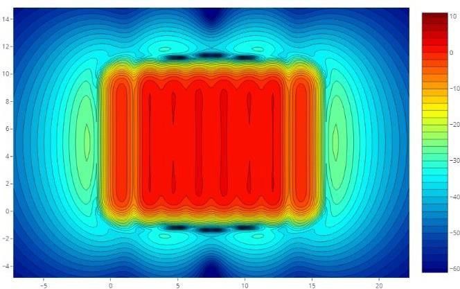
LD Series | Installation and user manual

   User manual                             2
LD Series | Installation and user manual

                                        TABLE OF CONTENTS| EN

        1. Introduction                                                   5
        1.1 Purpose                                                       5
        1.2 Target audience                                               5
        1.3 Alerts                                                        5
        1.4 Icons                                                         5
        2. Loop amplifier presentation                                    6
        2.1 Description                                                   6
        2.2 The product range                                             6
        2.3 Package contents                                              6
        2.4 Rack mounting kit: OP-R (optional)                            6
        2.5 Advice and safety                                             7
        3. Technology presentation                                       8
        3.1 What is an AFILS (Audio Frequency Induction Loop System) ?    8
        3.2 Working principle                                            8
        4. Controls, connections and adjustments                         9
        4.1 Control                                                      9
        4.2 Multi-loop output                                            9
        4.3 Front panel and adjustments                                  10
        4.4 Rear panel and adjustments                                   11
        4.5 Rack mounting                                                12
        4.6 Adjustment and connection                                    14
        4.7 Connecting two amplifiers                                    16
        5. Setup                                                         18
        5.1 Setting up a simple perimeter loop                           18
        5.2 Setting up a Master and a Slave amplifiers                   18
        5.3 Securing the settings                                        19
        5.4 Metal loss compensation adjustment                           19
        5.5 Operation of the fault contact                               19
        5.6 Audio input                                                  19
        6. Functioning and planning of a loop system                     20
        6.1 Preamble                                                     20
        6.2 Working principle                                            20
        6.3 The different types of installation                          21

   User manual                                                                3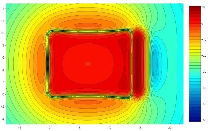
LD Series | Installation and user manual

                                       TABLE OF CONTENTS| EN

        7. The magnetic induction loop                          23
        7.1 Installing your loop                                23
        7.2 Cable section                                       23
        7.3 Connection                                          23
        7.4 The magnetic field                                  23
        7.5 Technical study                                     24
        8. Installation constraints                             27
        8.1 Magnetic overspill                                  27
        8.2 Metal distortion                                    27
        9. Information                                          28
        9.1 Maintenance and care                                28
        9.2 Warranty                                            28
        9.3 After-sales service and return                      28
        9.4 Disposal of used electric and electronic units      28
        9.5 Technical specifications                            29
        9.6 CE certification                                    30
        Certificate of conformity to the IEC-60118-4 standard   31

   User manual                                                       4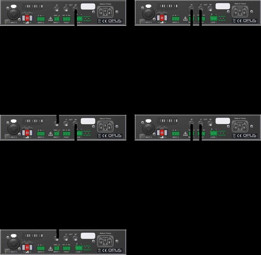
LD Series | Installation and user manual

   1. Introduction                                           1.4 Icons

   Thank you for having purchased an Opus Technologies       1.4.1 Note Icons
   LD SERIES class D loop amplifier. Please take a few
   moments to read this manual and follow the                Warning icons used with the notes provide additional
   recommended instructions, it will ensure the optimal      information about the note. See the following
   use of the product and many years of flawless service.    examples:
   Keep this instruction manual in accessible place.

   1.1 Purpose                                                                                             Note:
                                                                                                General Note Icon
   The installation and user manual provides the needed
   informations to install, configure and to use your LD
   Series amplifier.

   1.2 Target audience                                                                                       Note:
                                                                                           Symbol referring to the
                                                                                     indicated information source.
   The installation and user manual is destined to Opus
   Technologies’ LD Series amplifiers installers and
   users.

   1.3 Alerts                                                1.4.2 Caution and warning icons

   This manual mentions different types of warning.
   The type of alert is closely related to the effect that   The icons used in combination with Caution and
   may occur if the alert is not observed. These alerts,     Warning indicate the type of risk. See the following
   ranked in increasing order of severity, are as follows:   examples:

   • Caution                                                          This symbol is used to alert the user to
   Failure to follow a cautionary warning may result in               important operating or maintenance
   property damage.                                                   instruction

   • Warning                                                          This lightening bolt triangle is used to
   Failure to heed a warning may result in serious                    alert the user to the risk of electic shock
   property damage and potential personal injury.

                                                                         This symbol alert the user to important
                                                                         risk of electrostatic discharge

                                                                          This symbol alert the user to important
                                                                          risk of burn if customer is touching the
                                                                          device while operating

   User manual                                                                                                       5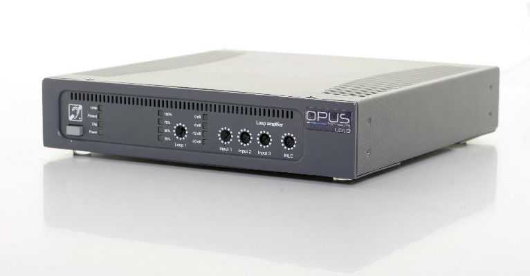
LD Series | Installation and user manual

   2. Loop amplifier presentation                               2.3 Package contents

   2.1 Description                                              Upon reception of your amplifier, inspect the unit to
                                                                check if any damage have occurred during shipment.
   The LD range is composed of magnetic induction loop          If damages are noticed, report immediately to your
   amplifiers allowing to equip rooms for people                distributor and shipping company, indicating the
   suffering from hearing loss.                                 date of delivery, the nature of the damage, if it was
                                                                visible on the packaging before unpacking. If
   The LD Series has been developed with strict and             possible, give the delivery note number and a
   rigorous specifications that allow us to offer a 5 year      tracking number.
   warranty. The products have been designed with
   options to facilitate their use and installation.
                                                                Package contents:

                                                                • LD1.0, LD2.0 or LD3.0 amplifier
             Product picture Figure1                            • Power cable 1.5m, CEE 7/7 - C13 connectors
                                                                • 2x 3-pin connectors
   The range of single channel amplifiers is composed of
                                                                • 1x 2-pin connector, output
   the LD1.2, LD2.2 and LD3.2. They allow to cover
                                                                • 1x 2-pin connector, input
   different surfaces as described below.
                                                                • A set of 3 stickers “Area adapted for the hard of
                                                                  hearing people".
   2.2 The product range                                        • Installation and user guide
                                                                • OP-R rack mounting kit (optional)
   Opus Technologies' LD1.0, LD2.0 and LD3.0 are a new          • Warranty certificate
   generation of magnetic loop amplifiers, made in
   France. These robust amplifiers are the most compact         If any pieces are missing, please contact your reseller
   on the market while offering the necessary features          or the manufacturer directly.
   (AGC, MLC, compressor, fault monitoring, etc.) to
   ensure an installation in rooms from 100m² to
   1000m².
                                                                2.4 Rack mounting kit: OP-R (optional)
   • LD1.0 covers up to 250 m² - max width : 10m
   • LD2.0 covers up to 450 m² - max width : 15m
                                                                OP-R contents
   • LD3.0 covers up to 1000 m² - max width : 20m
                                                                • 2x rack mounting brackets
                                                                • 2x mounting brackets
   These coverage informations are given on an
                                                                • 8x mounting screws
   indicative basis and depend on the configuration of
   the room and project constraints (presence of metal
   structures, overspill, room width, etc). Not taking
   these constraints may lead to an installation not
   complying      with     the     IEC-60118-4     standard
   requirements. It is essential to consult a loop specialist
   for your project design. Our Smartloop simulation
   software will help you designing project complying
   with the IEC-60118-4 norm. Contact your closest
   distributor for more information.

                                                                                     Amplifier picture -Figure1

   User manual                                                                                                            6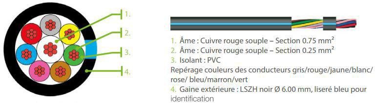
LD Series | Installation and user manual

  2.5 Advice and safety                                      • Do not cover the air vents so that any heat
                                                               generated by the device can be dissipated by
   Most of defective loop installations are the result of      air circulation.
  a lack of preparation. Take your time before starting      • Depending on the stress it is exposed to, the
  your installation and always keep this manual in an          device can develop high temperatures in the
  accessible place.                                            heat sink and at the air vents. Be careful not to
                                                               touch these elements - risk of burns.
  Ideally, the loop driver should be placed near the         • An installation must be carried out by qualified
  area to be covered. This may involve placing the loop        personnel.
  driver on a panel/wall, under a desk or under a            • The device must be out of reach of
  counter. Wall mounting accessories are provided in           unauthorized persons.
  the OP-R mounting kit.                                     • The device may only be operated by trained
                                                               staff qualified for loop installation.
                                                             • The device is intended to be used for inductive
                    Refer to figure 9 on page 13               loop systems only.
                                                             • To prevent potential injury, do not position
                                                               this device higher than 2 meters from the
  To chose the location for your loop, take into               ground.
  consideration the area that would be most likely           • Connect the loop driver only to wiring which
  used by the end user. This area is called the                complies to IEC-60364.
  “listening area”.                                          • In order to prevent children and people in
                                                               general to get injured, the amplifier must be
  For exemple, in a concert hall, you'll install your loop     installed in a locked technical room only
  cable around the audiance area rather than the               accessible to trained authorized people.
  whole room. Covering also the stage may lead to            • The amplifier must be earthed / grounded.
  feedbacks effect due to a conflict between the loop        • Refer all servicing to a qualified staff. Servicing
  magnetic field and the dynamic microphones (guitar,          is required when the device has been damaged
  bass..) of the band playing on the stage.                    in any way, such as a power supply cord or
                                                               plug is damaged, liquid has been spilled or
  • Clean the device only with a dry cloth. Cleaning           objects have fallen into the device, if it have
    fluids may affect the equipment.                           been exposed to any rain or moisture, does
  • Do not block any ventilation openings. Install in          not operate normally or has been dropped.
    accordance with the manufacturer’s instructions.
                                                             • TO PREVENT ELECTRIC SHOCK DO NOT
  • Do not install this equipment near any heat                REMOVE THE COVER. THERE ARE NO USER
    sources such as radiators, heating vents or other          SERVICEABLE PARTS INSIDE. REFER SERVICING
    apparatus that produces heat.                              TO QUALIFIED STAFF.
  • Only power cords with the correct power                  • Warning : Connection to a 100V line system
    connector may be used to maintain safety. These            may involve the risk of electric shock. And
    must be plugged into power outlets which provide           therefore must be carried out by an instructed
    a protective earth.                                        or skilled person.
  • To prevent accidents or personal injury caused by
    electrical shocks, never place any type of
    container filled with a liquid, such as a vase, on or
    around the device.
  • Never pull on the power cord to remove the plug
    from the wall outlet; always pull the plug.
  • Do not operate the device near heat sources or in
    rooms      with     high     humidity.     (Operating
    temperature range 0-45°C).

   User manual                                                                                                   7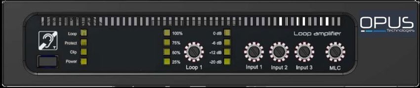
LD Series | Installation and user manual

  3. Technology presentation                                      The audio source can come from various origins. In a
                                                                  cinema, for example, the sound of the film will be
  3.1 What is an AFILS (Audio Frequency                           transmitted. In a conference room, the sound of the
  Induction Loop System)?                                         speaker's microphone will be transmitted. In a
                                                                  subway station, the voice of the agent will be
  An induction loop system is intented to help hard of            transmitted...
  hearing people to receive a clear audio signal into             The loop can be installed on the floor or ceiling. The
  their hearing aid without being disturb by                      loop is integrated into the building, just like the
  background noises . Thanks to this system, the                  electrical installation.
  sound coming from an audio source (speaker                      The presence of a hearing loop is often indicated by
  microphone, sound system, television) is transmitted            a blue logo representing a barred ear and the letter
  by induction to hearing aid user who can thus enjoy             "T".
  clear sound without being disturbed by any ambient
  noise. This system is mainly used in public places
  (conference rooms, cinemas, courts, churches, ticket
  offices, etc.) but can also be installed at home. Many
  conventional hearing aids have a "T" loop function.                                    Refer to figure 2

   3.2 Working principle
   A magnetic loop system consists of an electric wire
   Layed down around a room forming a loop. The
   cable is connected to a loop amplifier, connected
   itself to an audio source. The loop amplifier convert
   the audio signal into electric pulses transmitted                                   Pictogram used to indicate a loop
   through the cable, creating a magnetic field. Heairing                                             system - Figure 2
   aids equipped with a coil (often called a "T" or "T-
   coil". ) will capture this signal and transmit it to
   hearing impared.

   By induction, the electrical signal present in the loop
   ill be reflected in the coil of the hearing aid. The coil
   transmits the signal of the loop in the internal
   amplifier of the prosthesis, which then bring it to the
   ear of the hearing impaired person, free of
   background noise and environmental disturbances.

                                                          Hearing aid operating diagram with the T-position - Figure 3

   User manual                                                                                                             8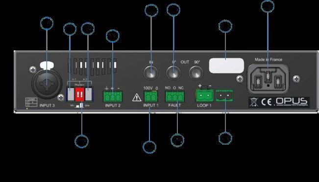
LD Series | Installation and user manual

     4. Controls, connections and adjustments

     4.1 Control

     The amplifiers comes with a fault synthesis allowing
     you to monitor the main functions of the unit, such
     as the amplifier’s power, the integrity of the loop
     cable connected to the amplifier and the inputs.

     If any of the functions are faulty and not working
     properly, a red LED on the front panel of the
     amplifier lights up and the fault relay opens (NO:
     Normally Open).

     4.2 Multi-loop output

     The LD1.0, LD2.0 and LD3.0 amplifiers have two OUT
     0° and 90° outputs and one IN input on the rear
     panel (see Figure 5 on page 11). This feature offers
     the possibility of combining several amplifiers
     together.
     Depending on the layout of the loops, the aim is to
     control the external overspill of the magnetic field
     and/or the homogeneity of coverage or the coverage
     area.

            Refer to section Layout page – 24

     For more information on the installation of a loop
     using a master loop and a 90° phased shifted slave
     loop, contact your local distributor, contact your local
     distributor.
     You can also use our Opus Smartloop simulation
     software or contact us at
     contact@opus-technologies.fr.

   User manual                                                  9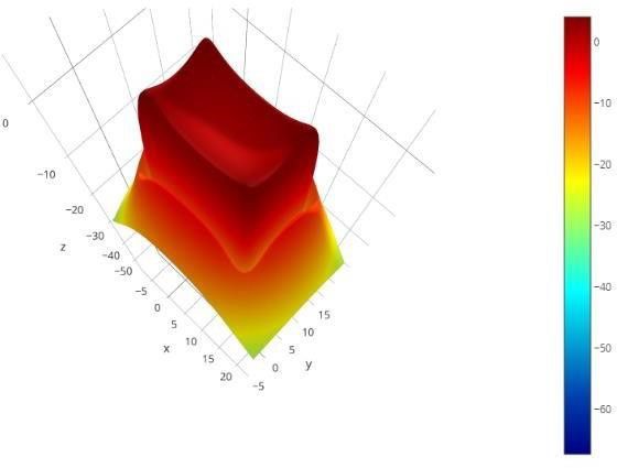
LD Series | Installation and user manual

   4.3 Front panel and adjustments

                                                                                               Front panel - Figure 4

   1. "Protect" LED, fault summary display. Error indicator. This red LED lights up when the master loop amplifier is
      overloaded, when the input level of the master loop is too high or when the master loop is defective.

   2. “Loop" LED, loop presence. This green LED is displayed when the loop is in working condition.

   3. Output current adjustment. Allows you to control the electrical output current distributed in the loop.

   4. INPUT 3 (100V) input adjustment. This controls the signal of the INPUT 3.

   5. INPUT 2 (line or microphone) input adjustment. Allows to control the signal of the INPUT 2.

   6. INPUT 1 (line or microphone) input adjustment. Allows to control the signal of the INPUT 1.

   7. ON/OFF power push button.

   8. “Clip" LED, amplifier saturation display. Error indicator. This red LED lights up when the Slave loop amplifier is
      overloaded, when the input level of the Slave loop is too high or when the Slave loop is faulty.

   9. “Power" LED, ON/OFF display. Power on indicator light.

   10. Input signal meter. Indicates the input signal level after adjustment.

   11. Output signal meter. Indicates the electrical current in the induction loop.

   12. MLC (Metal Loss Compensation) setting reduces interference problems due to the presence of metal
       structures.

   User manual                                                                                                          10
LD Series | Installation and user manual
4.4 Rear panel and adjustments
Rear panel - Figure5
13. INPUT 3 Combo audio input: microphone or line. This input allows you to connect external audio inputs from a
line level source (mixer, pre-amp, etc.) or from a microphone. The Combo connector accepts an XLR or a 6.35 jack.
14. Push button for line or microphone communication of the INPUT 1 input. Switch to commute the input
according to the source (microphone or line).
15. Push button for line or microphone communication of the INPUT 2 input. Switch allowing to commute the input
according to the source (microphone or line).
16. INPUT 2 Phoenix type terminal block: microphone or line. This terminal block input is used to connect external
audio inputs from a line level source (mixer, preamp, etc.) or from a microphone.
17. INPUT 1 Phoenix type terminal block: 100V priority. This terminal block input allows you to connect an external
audio input from a 100V sound system, the audio is directly recovered from the speaker’s line. Please ensure the
connexion is done by a trained staff only. Risk of injury.
18. Slave IN input. This input is used to connect a 0° or 90° output (Master/Slave) from another LD series loop
amplifier.
19. 0° or 90° OUT output to slave amplifier. These outputs are used to connect the Master amplifier to a Slave loop
amplifier from the LD range.
20. Location of the serial number label.
21. Mains power cord connection. Connects the loop amplifier to the power supply.
22. Phantom power selection switch. Allows you to send or not voltage to supply a microphone connected to INPUT
1 and/or INPUT 2.
23. NO/NC fault relay. Allows the system status information to be sent via a relay.
24. Loop output on Phoenix type terminal block. Allows to connect the loop wire to the amplifier.
User manual 11LD Series | Installation and user manual
4.5 Rack mounting 4.5.2 Rack integration
4.5.1 Ventilation and rack mounting Required accessory: OP-R* mounting kit
The location must provide adequat Attach the rack mounting brackets as shown below
ventilation for the unit. (Figure 7) using the mounting screws provided in the kit.
For better ventilation we recommend leaving a space
of 1U (44 mm) above the amplifier.
Then integrate the amplifier into the rack.
Leave at least 168 mm (5.5") of space between the
bottom of the rack and the amplifier.
Illustration of the
amplifier integration in
a rack - Figure 7
Amplifier ventilation- Figure 6
Caution, warning, danger:
The LD1.0, LD2.0, LD3.0 amplifiers contain
an advanced protection circuit, which
allows them to reduce the output power
to maintain safe operating temperatures. Insufficient
ventilation may cause a reduction of the amplifier’
output power during normal operation (indicated by
illumination of the red CLIP / PROTECT 2 LEDs). To
reduce the risk of thermal limitation and allow
proper heat dissipation, it is recommended to keep
clear the space directly above and behind these
amplifiers.It is also highly recommended not to place
anything directly on top of the amplifier.
*The OP-R mounting kit is not supplied with the
one-channel amplifiers (LD1.0, LD2.0 and LD3.0)
of the LD series.
User manual 12LD Series | Installation and user manual
4.5.3 Rack-mounting two loop amplifiers 4.5.4 Mounting the loop amplifier on a wall
Required accessory: OP-R* mounting kit Required accessory: OP-R* mounting kit
Attach the rack mounting brackets as shown below Attach the mounting brackets as shown below (Figure 9)
(Figure 8) using the mounting screws provided in the kit. using the screws provided in the kit.
Then attach the amplifiers to each other with the
Then, attach the amplifier to the selected wall.
mounting brackets.
Finally, integrate the amplifier into the rack.
Note: The OP-R mounting kit is not supplied with the
one-channel amplifiers (LD1.0, LD2.0 and LD3.0) of the
LD series.
Illustration of 2 amplifiers integrated
in a rack - Figure 8 Illustration of an amplifier integration
on a wall - Figure 9
*The OP-R mounting kit is not supplied with the
one-channel amplifiers (LD1.0, LD2.0 and LD3.0)
of the LD series.
User manual 13LD Series | Installation and user manual
4.6 Adjustment and connection
4.6.4 Input and outputs jack 6.35
4.6.1 Loop connection
On the rear panel of the amplifier you can see three
The loop is connected via a green 2-point terminal 6.35 jack inputs. These inputs and outputs allow you
block located on the rear panel of the amplifier, to connect several loop amplifiers together to create
thanks to a twisted cable. single phased loop systems, low loss systems or ultra
low loss systems.
Distance between the loop and the Refer to the types of connection in paragraph 4.7 and
amplifier must not exceed 15 m. the different types of installation in paragraph 6.
The twisted cable cancels the magnetic 4.6.5 Line output
field and avoids inductions potentially created by
transformers external to the system. The references It is possible to connect a recorder to the line output
OP-LI5/10 or 15 allow to create this type of of the loop amplifier. The line output of the amplifier
connection. is a 6.35 OUT 0° jack which is mainly used to link
several amplifiers when setting up complex systems
(low spill system) but the output can also be used as a
single line output.
The loop circuit must use cabling conforming to the
IEC-60332-1-2, 60332-1-3, 60332-2-1, 60332-2-2 or
60695-11-21 standards.
4.6.6 Power supply
4.6.2 Audio inputs
The LD amplifiers have an integrated power supply of
230V (or 115V), with a power of 300VA.
The audio sources are connected via the 3 inputs
of the amplifier provided for this purpose. The
LD Series have 3 inputs:
• Input 1: 100 V 4.6.7 Status relay
• Input 2: lines or microphones
• Input 3: lines or microphones The status output is used to send a status of the loop
amplifier to external devices via a NO/NC relay.
4.6.3 Priority INPUT 1 100V input
The INPUT 1 (100V) of the LD series amplifiers has a 4.6.8 Connectors
priority for security sound systems in case of 3 pin-XLR
evacuation of the building. Symmetric: PUSH
If more than one audio source reaches the Pin 1 : Mass/Ground/ Schield
Pin 2 : 2 1
amplifier's inputs, the priority input will always have Hot spot (+)
priority over the others, and the INPUT 2 and/or Pin 3 : Cold spot(-) 3
INPUT 3 will be muted. In some cases, and if the Asymmetric:
configuration allows it, we recommend connecting Pin 1 : Mass/Ground
the room sound system to INPUT 2 and INPUT 3 and Pin 2 : Signal (+)
the security sound system to INPUT 1. Pin 3 : Connected to mass (pin 1)
Warning : Connection to a 100V line Hot spot Cold spot Mass
system may involve the risk of
electric shock and therefore must be
carried out by an instructed or skilled
person.
6.35 mm jack
User manual 14LD Series | Installation and user manual
4.6 Adjustment and connection 4.6.11 Protect and Clip LEDs
4.6.9 Switching on The " Protect " and " Clip " LEDs light up if :
• The ohmic resistance of the inductive loop is
Loop not between 0.5 and 3 Ohm.
• The corresponding conductor section is
Protect overloaded or overheated.
• The input level is too high, causing clipping of
Clip the audio signal.
Power
The unit is powered up using the grey switch on the
front of the amplifier. If the amplifier is powered up
the Power LED will light up in blue.
To turn the unit off, press again the Power switch on
the front of the amplifier again. Please note that the
unit goes into standby mode when it is turned off.
Unplug the power plug from the wall outlet to
completely turn off the unit.
4.6.10 Loop integrity
The green LED on the front of the amplifier is used to
check the loop integrity. If the loop is cut or if the
loop impedance is not between 0.5 and 3 Ohm the
Loop LED will not be displayed and the Protect LED
will be light up. (See figure below)
Loop
Protect
Loop OK
Clip
Power
Loop
Protect
× Loop fault, input too high and/or
Clip amplifier overloaded
Power
User manual 15LD Series | Installation and user manual
4.7 Connecting two amplifiers
4.7.1 Master over 1 Slave
Master amplifier Slave amplifier
90° output to Slave Input on slave amplifier
amplifier IN
OUT
To expand and duplicate an installation or to use a low spill system or high coverage system with the LD Series
1-channel amplifiers:
1. Connect the loops to the terminals provided: amplifier Loop terminal.
2. Insert an audio source into INPUT 1, 2 or 3 of the master amplifier.
3. Connect the OUT 90° output of the Master amplifier to the Slave amplifier using a 6.35mm link cable.
4. Turn on the amplifiers and adjust them accordingly.
4.7.2 Slave to slave
Connect the OUT jack (0° or 90°) of the slave loop amplifier to the IN jack of the next slave loop amplifier.
This allows you to connect several slave amplifiers. (See diagram on next page)
This allows you to use multiple amplifiers on the same input. This can be useful for very large rooms or if several
rooms share the same audio transmission.
User manual 16LD Series | Installation and user manual
4.7.3 Master to several slaves
Master amplifier Slave 1 amplifier
90° output to Input on slave 1
amplifier Slave amplifier
OUT IN
and 0° output to slave
amplifier
OUT
Slave 2 amplifier Slave 3 amplifier
Input on slave 2 Input on slave 3
amplifier amplifier
IN IN
and 90° output to slave and 0° output to slave
amplifier amplifier
OUT OUT
Slave 4 amplifier
Input on amplifier Slave 4
IN
To use a low spill or very high coverage system:
1. Connect the OUT 90° jack of the master loop amplifier to the IN jack of the next slave loop amplifier (Slave
Amplifier 1).
2. Connect the OUT 0° socket of amplifier 1 to the IN socket of the next amplifier (unit 2).
3. Connect the OUT 90° socket of amplifier 2 to the IN socket of the next amplifier (unit 3).
4. Connect the OUT 0° socket of amplifier 3 to the IN socket of the next amplifier (unit 4).
5. Repeat if necessary.
6. Connect the respective out-of-phase loops to the terminal blocks of the corresponding amplifiers.
7. Switch on the amplifiers and adjust them accordingly.
This type of configuration will be used to cover large areas such as those of exhibition parks or sports halls or to
equip several areas with the same audio source.
User manual 17LD Series | Installation and user manual
5. Setup
5.1 Setting up a simple perimeter loop The Master amplifier is the unit to which the audio
signal at input 1, 2 or 3 is connected. This will be
the basic signal. The phase shift module integrated
1. Turn on your amplifier and check that all the in the units will then shift this signal by 90° or 0° to
potentiometers are at 0 level inject it into the next slave amplifier.
2. Connect your loop to the Loop 1 terminal block
3. Connect a 1kHz sinusoidal source to one of the
inputs There is no special adjustment to determine the
4. Increase the input signal via the potentiometer on Slave amplifier, only the connection arrangement
the front of the amplifier until you reach between will define the Slave and Master amplifiers.
-6 and 0 dB.
5. Increase the output current via the Loop 1
potentiometer on the front panel of the amplifier
1. Power up your amplifier and check that all the
until you reach between 75% and 85%.
potentiometers are at 0
6. Take a magnetic field meter such as OP-FSM* and
2. Connect your loop to the Loop1 terminal block
make a first measurement at the center of your
3. Connect a 1kHz sinusoidal source to one of the
room.
inputs
7. Then readjust the settings until you reach -3dB at
4. Increase the input signal via the potentiometer
the center of the zone
on the front of the amplifier until you reach
8. Then follow the test procedure described in the
between -6 and 0 dB of the input meter
OP-FSM manual for an installation that meets the
5. Increase the output current via the Loop 1
IEC-60118-4 standard.
button on the front panel of the amplifier until
you reach between 75% and 85%.
6. Take a magnetic field mesurer such as OP-FSM
5.2 Setting up a Master and a Slave amplifiers and make a first measurement at the center of
your room
7. Then adjust the settings according to the
5.2.1 Master loop amplifier measurements made with your magnetic field
mesurer in order to achieve homogeneous
To know the different types of implementation of a coverage in accordance with the IEC60118-4
low spill loop system or single phased loops, refer to standard.
paragraphs 6.3.2 and 6.3.3.
Depending on the type of LD series amplifier, the 5.2.2 Slave loop amplifier
settings will be different:
8. Turn on your amplifier and check that all the
• LD1.0/2.0/3.0 series units (not covered in this user potentiometers are at 0 level
manual) incorporate one amplifier per unit so 9. Connect your loop to the Loop 1 terminal
you’ll need two devices to process a phase shift block
Installation 10. Connect the master amplifier via a 6.35mm
• LD1.2/2.2/3.2 series incorporate two amplifier in jack cable to the 6.35mm IN jack
one unit allowing you to use only one device for 11. Increase the output current via the Loop 1
low spill systems. A second device will be required button on the front panel of the amplifier
whenever a 3rd loop is installed. until you reach between 75% and 85%.
12. Take a magnetic field meter such as OP-FSM
and make a first measurement at the center
of your room
User manual 18LD Series | Installation and user manual
5.2.3 Final adjustments If the fault synthesis detects an operating problem
(broken loop, wrong loop impedance, amplifier
13. Connect the two loops and then adjust the failure, etc.) the NO/NC relay is deactivated in the
settings until a minimum signal of -3dB is achieved normally open position: NO.
in the weakest audio reception area.
14. Then follow the test procedure described in the
OP-FSM manual to perform an installation 5.6. Audio input
according to the IEC-60118-4 standard.
5.6.1 Sensitivity
Note: You can download a sample certificate of
conformity from our website www.opus-
technologies.fr in the download section. Or use the
one provided at the end of this manual.
For more information on IEC-60118-4 standard IN 3 IN 2
adjustments contact us at contact@opus- Mic PhantomLine
technologies.fr or contact your local reseller.
5.3 Securing the settings
The level of INPUT 2 and INPUT 3 can be adjusted
The OP-V plexiglass plate (option: not supplied)
according to the audio source used.
allows you to lock the settings while viewing the
amplifier's information • When the audio source connected to one of the
inputs is a microphone, set the grey button to the
LEDs.
Mic position.
This plexiglass can be
• When the audio source connected to one of the
installed with or
inputs is line level, position the grey button
without the OP-R
released on the Line position.
rack system.
5.6.2 Phantom power
5.4 Metal loss compensation adjustment
The Phantom DIP switch on the rear panel of the
amplifier (see previous figure) enables or disables
phantom power for microphones that require
If you detect signal distortion due to voltage to operate.
presence of metal structure turn the
MLC (Metal Loss Compensation) control
When using a phantom power:
on the front panel of the amplifier
clockwise. • If the audio source of the INPUT 2 and/or INPUT
3 is a microphone that needs voltage:
Check your high frequency measurements with a 4kHz o The DIP switch must be up
sinusoidal signal and adjust the compensation settings to • When the audio source of the INPUT 2 and/or
achieve acceptable measurements to the IEC-60118-4 INPUT 3 is a microphone does not require
standard. voltage:
o The DIP switch must be down
• If the audio source is music:
5.5 Operation of the fault contact
o The DIP switch must be down
When the amplifier is working
properly, the NO/NC relay is
activated in the normally closed
position: NC.
User manual 19LD Series | Installation and user manual
6. Functioning and planning of a loop system 6.2.2 Magnetic field diffusion in a loop
6.1 Preamble When the intensity of the current flowing in a loop is
adapted to the width of the room to be equipped, the
A study revealed that more than 60% of the radiation of this one makes it possible to cover the
Magnetic Induction Loop installations do not work or whole room.
work poorly, far from the requirements of the
standard (IEC-60118-4). Indeed, the main difficulty
lies in the implementation of the loop path. This
observation led us to seek and provide effective
solutions to meet this standard.
It is therefore important to carefully read the
following instructions to ensure proper operation of
the system and compliance with the IEC-60018-4
standard. Do not hesitate to contact your local
distributor, we can help you with the study phase
before the installation of the system.
6.2 Working principle
6.2.1 The magnetic field
When an alternating current flows through a copper Top view of a loop installation in a room -
cable, it generates a magnetic field. Figure 11
The intensity of the magnetic field is directly related
to the intensity of the electric current flowing in the
No reception on the
cable. cable (shadow zone) Area with a constant
magnetic field
Audio reception Magnetic field
radiation
The floor
Cable (conductor)
Illustration of an electromagnetic wave
around a conductor - Figure 10 Sectional view of a loop installation in a
room - Figure 12
User manual 20LD Series | Installation and user manual
6.2.3 System composition 6.3.2 The simple 8 loop or phased array
A magnetic induction loop system is composed of In some configurations, it will be preferable to use an
: 8 loop rather than a single loop to generate a more
intense magnetic field on the surface to be covered.
• An amplifier This type of installation improves the coverage area.
• One or more loops created with a conductor
• An audio signal (microphone or line)
• In some configurations a twisted pair cable (Opus
references: OP-LI5/10 or 15).
Refer to figure 15
6.3 The different types of installation
6.3.1 Simple loop
A simple magnetic loop is composed of an amplifier
and one or more induction loops.
Installation of a simple 8 loop - Figure 14
Why the "8" loop?
• A magnetic loop in the shape of a number 8
allows to reduce the crosstalk of the magnetic
field.
• It allows to cover a larger surface and to have a a
better homogeneity of coverage.
Installation of a simple loop - Figure 13 • The current required is less important, so the
power consumption is also reduced.
Twisted cable for the Loop
connection between
the amplifier and the
loop (max 15m)
Audio source
Amplifier
Illustration of a complete magnetic loop system - Figure 15
User manual 21LD Series | Installation and user manual
6.3.3 Simple phased loops 6.3.4 Phased loops with low overflow
In order to allow a more extensive coverage in large When several rooms are adjacent to each other (one
spaces such as in an exhibition park, a sports hall or a next to each other or one on top of each other), it is
zenith, it is possible to install several simple loops by important to take into account the external radiation
using the input and the slave outputs. of the magnetic field. Indeed, if the amplifier is
adapted, a magnetic induction loop radiates
perfectly in the desired zone but also outside this
zone. Generally, the external coverage is equal to 4
time the width of the room. It is necessary to count 4
times the width to have a total isolation zone.
90°
In order to respond appropriately to this type of
IN Salve 3
problem, there is a type of installation that allows to
contain the overspill to the strict dimension of the
room. This type of installation also provides other
Out90°
advantages (see below).
0°
Slave 2
IN
Out0°
90°
Slave 1
IN
Out90°
0° IN
Slave
Master
Single loop installation - Figure 16
Out 90°
Refer to page 17 to view the Master
connection between the amplifiers for
this type of configuration.
Installation of a phased loop system - Figure 17
Why install low overflow multi-loops?
• Suppression of magnetic field directivity (vertical
and horizontal fields are transmitted).
• No attenuation in coverage.
• Reduced power consumption.
• Better signal reproduction.
• Reduced influence of metals.
• Reduced risk of feedback.
• Virtually no external radiation.
User manual 22LD Series | Installation and user manual
7. The magnetic induction loop The Loop Cable (LC-50/100/150) offers a variation
of sections from 0.5 to 2.5mm². See image below:
The installation of a magnetic induction loop is a
complex exercise. To ensure that it works perfectly, it
is important to take into account several essential
parameters and to adapt its installation to the
specificities of the room to be equipped.
The following points will help you maximizing the
audio quality and minimize the variation of the
magnetic field strength.
Loop Cable ( ref : LC-50/100/150)
7.1 Intsalling your loop
To locate the best place for the loop it is important to 7.3 Connection
determine the listening height (height of the human
ear) in the area to be equipped. For example, in a To connect the loop cable(s) to the amplifier, use a
conference room, people are seated, so the listening twisted cable to avoid unwanted inductions. We
height is between 1.10m and 1.40m. recommend not to move the amplifier more than 15
This position is very important to determine the m from the loop.
power required and therefore the type of amplifier to
be used to comply with the IEC-60118-4 installation
standard. It is important to note that the coverage 7.4 The magnetic field
data of our amplifiers are announced with a loop
installed on the ground and without disturbance. The strength of the magnetic field depends on the
Each project is different and must be studied before electric current impelled in the loop.
purchasing an amplifier. Opus Technologies has To meet the IEC-60118-4 standard, depending on the
developed Smartloop, a simulation software, which configuration of the room, 1.2m (for a seated
allows to study each project according to the person) or 1.70m (for a standing person) above the
constraints. floor in the listening area equipped with a magnetic
loop, the vertical fields must be 100 mA/m +/- 3 dB.
7.2 Cable section
The direct current resistance depends on the
diameter of the cable and its length. It should be
between 0.5 and 3 Ω for optimal operation of the
amplifiers. This result depends on the length of the
cable and its section, you can use our simulation
software Opus Smartloop or call your specialized
distributor to know the usable sections according to
the size for your project.
There are 2 types of cable for loop installation:
1. The copper foil to be installed under a lino,
parquet, carpet, etc. Opus references:
RC50/100/150
2. The classic flexible cable type H07RNF.
However, in order to avoid wire impedance
problems, Opus Technologies has developed a
variable resistance cable which allows to ensure
Magnetic field coverage simulation with Opus
90% of the loop installation needs and avoids
Smartloop software - Figure 18
cross section errors.
User manual 23LD Series | Installation and user manual
7.5 Technical study
Presentation of magnetic field data for a 15x10m room. Data from our simulation tool Opus Smartloop.
7.5.1 Perimeter loop
Simple loop installation Simple loop 2D simulation
Simple loop median Simple loop 3D simulation
Table of cable sections
User manual 24LD Series | Installation and user manual
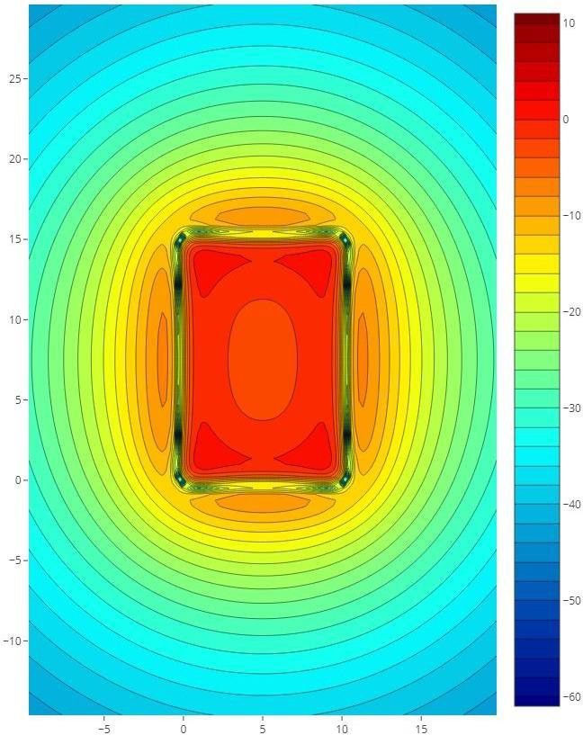
7.5 Technical study
Presentation of magnetic field data for a 15x10m room. Data from our simulation tool Opus Smartloop.
7.5.2 Cancellation loop
Cancellation loop installation Cancellation loop 2D simulation
Cancellation loop median Cancellation loop 3D simulation
Table of cable sections
User manual 25LD Series | Installation and user manual
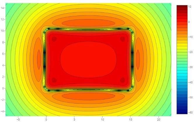
7.5 Technical study
Presentation of magnetic field data for a 15x10m room. Data from our simulation tool Opus Smartloop.
7.5.3 Ultra low overflow system
Ultra low overflow system installation Ultra low overflow system 2D simulation
Ultra low overflow system median Ultra low overflow system 3D simulation
In order to guarantee the compliance
with the IEC-60018-4 standard during
the installation of your magnetic
induction loop, Opus Technologies and
its local distributors will guide you in the
study and installation of your project.
Visit http://opus-technologies.fr/contact-us/ to
find your local distributor or write to us.
Table of cable sections
User manual 26LD Series | Installation and user manual 8. Installation constraints Some environments can create interference with the magnetic induction loops, here are the main causes. 8.1 Magnetic overspill The installation of a perimeter loop system is perfectly suitable to cover a room if the amplifier is correctly sized, however it is important to note that the magnetic field of a loop will cover the inside of the room but also the outside. The larger the loop will be, the more radiation it will have (note: in principle, 4 times the width of a loop is needed to have a total isolation zone). This phenomenon of external radiation can be problematic when it is necessary to equip several contiguous rooms or for reasons of confidentiality. To remedy this problem, it is possible to create low overflow installations that will avoid the radiation of the magnetic field. See paragraphs 6.3.3 and 7.5.3. 8.2 Metal distortion Metal distorts the magnetic field at high frequencies. Many buildings contain metal, especially in their structures. To limit the influence of metal we have created a tone compensation with the MLC (Metal Loss Compensation) setting on the front panel of the amplifiers. User manual 27
LD Series | Installation and user manual

    9. Information

    9.1 Maintenance and care                                      9.3 After-sales service and return

   Opus Technologies amplifiers do not require any           The Opus Technologies team is committed to
   maintenance. If the unit becomes dirty, simply wipe       providing fast and efficient after-sales service. In case
   it clean with a soft, damp cloth.                         of product misfunction you have to contact your local
   Note: Disconnect the LD series amplifier from the         distributor or write us at contact@opus-
   power supply first. Never use spirits, thinners or        technologies.fr.
   other organic solvents. Do not place the LD series
   amplifier where it will be exposed to full sunlight for
   long periods. In addition, it must be protected                       9.4 Disposal of used electric and
   against excessive heat, moisture and severe                           electronic units
   mechanical shocks.
   Note: This product is not protected against splash
                                                             (Applicable in the countries of the European Union
   water. Do not place any containers filled with water,
                                                             and other European countries with a separate
   such as flower vases, or anything with an open flame,
                                                             collection system).
   such as a lit candle, on or near the product.
                                                             The symbol on the product or the packaging
   When not used, store the device in a dry place,
                                                             indicates that this product is not to be handled as
   protected from dust.
                                                             ordinary household waste but has to be returned to
                                                             a collecting point for the recycling of electric and
                                                             electronic units. You protect the environment and
    9.2 Warranty                                             health of your fellow men by the correct disposal of
                                                             this products. Environment and health are
   Opus Technologies amplifiers are manufactured in          endangered by a faulty disposal. Material recycling
   France according to strict specifications guaranteeing    helps to reduce the consumption of raw material.
   quality and reliability.                                  You will receive further information on the recycling
   Should a malfunction occur despite the unit being set     of this product from your local community, your
   up and operated correctly, please contact your            communal disposal company or your local reseller.
   dealer or the manufacturer directly.
   Opus Technologies products have been designed to
   meet the needs of the end user and to offer the best
   possible audio performance and reliability. The
   quality of manufacturing allows us to offer our
   customers a 5-year manufacturer's warranty.
   This warranty covers the repair of the product and
   returning it to you free of charge. It is recommended
   that you send in the product in its original packaging,
   so keep the packaging for the duration of the
   warranty period. The warranty does not apply to
   damage caused by incorrect handling or attempts to
   repair the unit by people not authorised to do so
   (destruction of the product seal). Repairs will only be
   carried out under warranty if the completed
   warranty card is returned accompanied by a copy of
   the dealer’s invoice/till receipt.
   Always specify the product number in any event.

   User manual                                                                                                   28
LD Series | Installation and user manual
9.5 Technical specifications
LD1.0 LD2.0 LD3.0
Coverage 250 m² (10*25 m²) 450 m² (15*30 m²) 1000 m² (20*45 m²)
Operating 0 to +45°C 0 to +45°C 0 to +45°C
temperature
Storage temperature -30 to +70°C -30 to +70°C -30 to +70°C
INPUT
Audio inputs 3 inputs: x2 3 inputs: x2 3 inputs: x2
line/microphone, x1 100V line/microphone, x1 100V line/microphone, x1 100V
Connector type Phoenix and/or Combo Phoenix and/or Combo Phoenix and/or Combo
Neutrik Neutrik Neutrik
Phantom supply 12V 2mA 12V 2mA 12V 2mA
Sensitivity -50dB microphone, -50dB microphone, -50dB microphone,
+40dB 100V, -10dB line +40dB 100V, -10dB line +40dB 100V, -10dB line
Priority 100V input, INPUT 1 100V input, INPUT 1 100V input, INPUT 1
POWER SUPPLY
Type Integrated Integrated Integrated
Voltage 115/230V (automatic) 115/230V (automatic) 115/230V (automatic)
50/60 Hz 50/60 Hz 50/60 Hz
Nominal power 25 W 50 W 90 W
consumption at 1
Ohm
Maximum inputLD Series | Installation and user manual
9.5 Technical specifications
LD1.0 LD2.0 LD3.0
OUTPUT
Loop impedance 0,5Ω à 3Ω 0,5Ω à 3Ω 0,5Ω à 3Ω
Output voltage 34V rms (48V pK) 34V rms (48V pK) 34V rms (48V pK)
Peak current 8A pK 11A pK 15A pK
RMS current 5A rms 7A rms 10A rms
Slave output 0° or 90° phase shift 0° or 90° phase shift 0° or 90° phase shift
ADDITIONAL FUNCTIONS
LED display « Power », « Protect », « Power », « Protect », « Power », « Protect »,
« Clip », « Loop » « Clip », « Loop » « Clip », « Loop »
Metal loss correction 0 to 3 dB per octave 0 to 3 dB per octave 0 to 3 dB per octave
Relay NO/NC fault relay NO/NC fault relay NO/NC fault relay
0,5A/125Vac, 1A/24VDC 0,5A/125Vac, 1A/24VDC 0,5A/125Vac, 1A/24VDC
DIMENSIONS (MM)
HxLxD 42 x 200 x 215 mm 42 x 200 x 215 mm 42 x 200 x 215 mm
Weight 1,48 kg 1,48 kg 1,48 kg
9.6 CE certification
This device complies with the following CE directives:
- 2017 / 2102 / CE RoHS-directive
- 2012 / 19 / CE WEEE-directive
- 2014 / 35 / CE Low voltage directive
- 2014 / 30 / CE Electromagnetic Compatibility
Compliance with the directives listed above is
confirmed by the CE seal on the device. CE
compliance declarations are available on the Internet
at www.opus-technologies.fr.
Technical specifications are subject to change.
User manual 30LD Series | Installation and user manual User manual 31
Certificatde conformité IEC60118-4
                                         Installationdeboucleàinduction magnétiquepourmalentendants
                                                          Informations Client                                                      Informationssurl’installation
                                Client :                                                                         Installateur :
                                Salle:                                                                           Société :
                                Adresse:                                                                         Équipement :
                                                                                                                 N° série:
                                                                                                                 Testée par:
                                        CROQUIS DE LASALLE
                                 1      Dessinerlasalle etla zonedecouvertureenindiquantlespoints demesureetlesbruitsde fond
Couper le long des pointillés

                                        RECHERCHE DE BRUITS DE FOND ET INTERFÉRENCES
                                 2      Amplificateuréteint etOP-FSM en position« -20dB ». Noterles interférencestolérables ou polluées sur le croquis
                                        Attention:L’existencedezonespolluéespar desbruits de fondcomprometla conformitédusystèmeà la normeIEC60118-4

                                 Zonesàbruit acceptables>- 32 dB             □           Zonesàbruit tolérables >- 22dB            □                Zonespolluées< - 22dB             □
                                        EFFECTUER LESMESURES
                                 3      Indiquersur lecroquis6 à 8 pointscorrespondants aux mesureseffectuéesassises(A) etdebout (A1) à différents pointsde lasalle.
                                        Lanormestipule quela hauteur d’écouteestde 1.2m pour uneplaceassiseet1.7mdebout. Garderl’appareil de mesuretoujoursàla verticale.
                                Points demesure                     A          B          C         D          E          F        A1         B1         C1         D1        E1          F1
                                Champ magnétique(dB)
                                Avantréglagesavecbruitrose
                                Réponse en          100Hz
                                fréquences
                                Aprèsréglages       1KHz

                                                    5KHz
                                Champ magnétique(dB)
                                Après réglagesavecaudio

                                        REGLAGESEFFECTUÉS
                                 4      Dessinerci-contrelesréglages effectuéssurl’amplificateur
                                                                                                                                    Loop1     Loop2     Input1    Input2     Input3       MLC

                                        DERNIÈRES VÉRIFICATIONS
                                 5      Une fois les tests effectués, le personnel du lieu équipé doit êtreinforméet préparer à guider les malentendantsdans l’utilisation du système.
                                        L’autocollant« oreillebarrée T» doitêtrecollé etvisibledes visiteurs. Lescas contraires,l’installation nepourra pas êtredéclaréeconformeIEC60118-4

                                                                                                                                                                 OUI □ NON □
                                Personne formée:
                                                                                                                               Signalétique visible ?

                                Commentaires :

                                L’installationest conforme à la norme IEC60118-4                                                                      OUI        □          NON           □
                                Nom :                                                                                 Date :
                                Prénom:                                                                               Signature:
NOTES
NOTES
NOTES
For any additional questions, please contact us.

OPUS TECHNOL£OGIES — ZI Lagrange II — 9 Chemin de la Vieille Ferme — 33650 MARTILLAC
Tel: (+33)09.81.24.00/06. — Fax: (+33)09.82.63.22.56. — contact@opus-technologies.fr

06/2021

User manual                                                                                                            36
Amplificateur de boucle classe D

                                              LD SERIES

                     AMPLIFICATEUR BOUCLE 1 CANAL

                                              Manuel d’installationet
                                         FR   d’utilisation
                                              LD 1.0 / 2.0 / 3.0
LD Series | Manuel d’installation et d’utilisation
TABLE DES MATIÈRES | FR
1. Introduction 5
1.1 But 5
1.2 Public visé 5
1.3 Alertes 5
1.4 Icônes 5
2. Présentation de l’amplificateur 6
2.1 Description 6
2.2 La gamme 6
2.3 Le contenu 6
2.4 Kit de montage en rack : OP-R (option) 6
2.5 Conseils et sécurité 7
3. Présentation de la technologie 8
3.1 Qu’est-ce qu’un système de boucle ? 8
3.2 Principe de fonctionnement 8
4. Commandes, connexions et réglages 9
4.1 Contrôle 9
4.2 Sortie Multi-boucle 9
4.3 Face avant et réglages 10
4.4 Face arrière et réglages 11
4.5 Mise en rack 12
4.6 Réglage et branchement 14
4.7 Connexions de deux amplificateurs 16
5. Configuration 18
5.1 Réglage d’une boucle simple 18
5.2 Réglage d’un amplificateur maître et d’un amplificateur esclave 18
5.3 Verrouillage des réglages 19
5.4 Réglage de compensation de perte métallique 19
5.5 Fonctionnement du contact de défaut 19
5.6 Entrée Audio 19
6. Fonctionnement et planification d’un système de boucle 20
6.1 Préambule 20
6.2 Principe de fonctionnement 20
6.3 Les différents types d’implantation 21
Manuel 38
d'utilisationLD Series | Manuel d’installation et d’utilisation
TABLE DES MATIÈRES | FR
7. La boucle à induction magnétique 23
7.1 Positionner la boucle 23
7.2 Épaisseur du fil 23
7.3 Liaison 23
7.4 Le champ magnétique 23
7.5 Étude technique 24
8. Les contraintes d’installation 27
8.1 Rayonnement externe 27
8.2 Distorsion due au métal 27
9. Informations 28
9.1 Maintenance et entretien 28
9.2 Garantie 28
9.3 SAV et retour produit 28
9.4 Gestion des déchets électriques et électroniques 28
9.5 Caractéristiques techniques 29
9.6 Certification CE 30
Certificat de conformité à la norme IEC-60118-4 31
Manuel 39
d'utilisationLD Series | Manuel d’installation et d’utilisation
1. Introduction 1.4 Icônes
Nous vous remercions d'avoir acheté un amplificateur 1.4.1 Icônes et notes
de boucle de classe D LD SERIES d'Opus Technologies.
Veuillez prendre quelques instants pour lire ce manuel Les icônes utilisées avec les notes fournissent des
et suivre les instructions recommandées. Cela vous informations supplémentaires sur la note. Voir les
assurera une utilisation optimale du produit et de exemples suivants :
nombreuses années de service sans faille. Conservez
ce manuel d'instructions dans un endroit accessible.
1.1 But Note:
Icône Générale des notes
Le manuel d'installation et d'utilisation fournit les
informations nécessaires pour installer, configurer et
utiliser votre amplificateur LD Series.
1.2 Public visé Note:
Symbole renvoyant à la
source d'information
Ce manuel d'installation et d'utilisation est destiné
indiquée.
aux installateurs et aux utilisateurs des amplificateurs
de la série LD d'Opus Technologies.
1.3 Alertes 1.4.2 Icônes d’attention et d’avertissement
Ce manuel mentionne différents types d'alertes.
Le type d'alerte est étroitement lié à l'effet qui peut Les icônes utilisées indiquent le type de risque. Voir
se produire si l'alerte n'est pas observée. Ces alertes, les exemples suivants :
classées par ordre croissant de gravité, sont les
suivantes :
Ce symbole est utilisé pour attirer
• Attention l'attention de l'utilisateur sur des
instructions importantes relatives au
Le non-respect d'une mise en garde peut entraîner des
dommages matériels.
fonctionnement ou à l'entretien.
Ce triangle en forme d'éclair est utilisé
• Avertissement
Le non-respect d'un avertissement peut entraîner de pour avertir l'utilisateur du risque de
graves dommages matériels et des blessures choc électrique.
corporelles potentielles.
Ce symbole avertit l'utilisateur d'un
risque important de décharge
électrostatique.
Ce symbole avertit l'utilisateur d'un
risque important de brûlure si le client
touche l'appareil pendant son
fonctionnement.
Manuel 40
d'utilisationLD Series | Manuel d’installation et d’utilisation
2.5 Conseils et sécurité • Ne couvrez pas les ouvertures d'aération afin
que la chaleur générée par l'appareil puisse
La plupart des installations de boucles défectueuses être dissipée par la circulation de l'air.
sont le résultat d'un manque de préparation. Prenez • En fonction des contraintes auxquelles il est
votre temps avant de commencer votre installation et soumis, l'appareil peut atteindre des
conservez toujours ce manuel dans un endroit températures élevées dans le dissipateur
accessible. thermique et au niveau des ouvertures
Idéalement, l’amplificateur de boucle devra être d'aération. Veillez à ne pas toucher ces
placé près de la zone à couvrir. Cela peut impliquer de éléments : risque de brûlures.
placer l’amplificateur sur un panneau, sous un bureau • Une installation doit être effectuée par du
ou sous un comptoir. Les accessoires de montage personnel qualifié.
mural sont fournis dans le kit de montage OP-R. • L'appareil doit être hors de portée des
personnes non autorisées.
Voir figure 9 page 13 • L'appareil ne doit être utilisé que par du
personnel qualifié pour l'installation de boucles.
• Le dispositif est destiné à être utilisé
Pour positionner la boucle dans l’espace à équiper, il uniquement pour les systèmes de boucle à
est important de prendre en compte les futurs induction.
utilisateurs du système. • Pour éviter toute blessure potentielle, ne pas
placer cet appareil à plus de 2 mètres du sol.
Par exemple, si vous devez seulement prévoir la • Connectez l’amplificateur de boucle
couverture dans la zone d’écoute d’une salle uniquement à un câblage conforme à la norme
polyvalente, une couverture réduite à la zone du IEC-60364.
public sera dans de nombreux cas une meilleure • Afin d'éviter que les enfants et les personnes en
solution qu’une boucle autour du périmètre de la général ne se blessent, l'amplificateur doit être
pièce. Ce type d’implantation évitera de couvrir la installé dans un local technique fermé à clé et
scène et donc les effets de Larsen possibles avec les accessible uniquement aux personnes
micros dynamiques (guitare, basse, etc.). autorisées et formées.
• L'amplificateur doit être branché à une prise
• Nettoyez l'appareil uniquement avec un chiffon de terre.
sec. Les liquides de nettoyage peuvent affecter • Confiez toutes les réparations à un personnel
l'équipement. qualifié. Une réparation est nécessaire lorsque
• N’obstruez pas les ouvertures de ventilation. l'appareil a été endommagé de quelque
Installez l'appareil conformément aux instructions manière que ce soit, par exemple lorsque le
du fabricant. cordon d'alimentation ou la fiche sont
• N'installez pas cet équipement à proximité de endommagés, lorsqu'un liquide a été renversé
sources de chaleur telles que des radiateurs, des ou que des objets sont tombés sur l'appareil,
bouches de chauffage ou tout autre appareil lorsqu'il a été exposé à la pluie ou à l'humidité,
produisant de la chaleur. lorsqu'il ne fonctionne pas normalement ou
• Pour des raisons de sécurité, seuls les cordons lorsqu'il est tombé.
d'alimentation dotés d’une fiche adaptée selon le • POUR ÉVITER TOUT CHOC ÉLECTRIQUE, NE PAS
pays peuvent être utilisés. Ils doivent être RETIRER LE COUVERCLE. IL N'Y A PAS DE PIÈCES
branchés sur des prises de terre. RÉPARABLES PAR L'UTILISATEUR À
• Afin d'éviter les accidents ou les blessures causés L'INTÉRIEUR. CONFIEZ L'ENTRETIEN DE
par des chocs électriques, ne placez jamais un L'APPAREIL À UN PERSONNEL QUALIFIÉ.
récipient rempli de liquide, tel qu'un vase, sur ou • Avertissement : le raccordement d’un
à proximité de l'appareil. amplificateur à une ligne 100 V peut entraîner
• Ne tirez jamais sur le cordon d'alimentation pour un risque d'électrocution. Il doit donc être
retirer la fiche de la prise murale ; tirez toujours effectué par une personne qualifiée.
sur la fiche.
• Ne faites pas fonctionner l'appareil à proximité de
sources de chaleur ou dans des pièces à forte
humidité. (Plage de température de
fonctionnement : 0-45°C).
Manuel 41
d'utilisationYou can also read