TERROVA BOW-MOUNT TROLLING MOTOR - Installation Instructions - Johnson ...
←
→
Page content transcription
If your browser does not render page correctly, please read the page content below
TERROVA
BOW-MOUNT TROLLING MOTOR
     Installation Instructions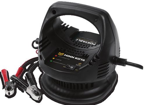
INTRODUCTION

  THANK YOU
  Thank you for choosing Minn Kota. We believe that you should spend more time fishing and less time positioning your boat. That’s why
  we build the smartest, toughest, most intuitive trolling motors on the water. Every aspect of a Minn Kota trolling motor is thought out
  and rethought until it’s good enough to bear our name. Countless hours of research and testing provide you the Minn Kota advantage
  that can truly take you “Anywhere. Anytime.” We don’t believe in shortcuts. We are Minn Kota. And we are never done helping you
  catch more fish.

  REGISTRATION
  Remember to keep your receipt and immediately register
  your trolling motor. A registration card is included with your
  motor or you can complete registration on our website at
  minnkotamotors.com.

  SERIAL NUMBER
  Your Minn Kota 11-character serial number is very important. It
  helps to determine the specific model and year of manufacture.
  When contacting Consumer Service or registering your product,
                                                                           Made by Minn Kota
                                                                                                          TERROVA 55-54"_BT
  you will need to know your product’s serial number. We                   Johnson Outdoors
                                                                           Marine Electronics, Inc.
                                                                           121 Power Drive
                                                                                                            MODEL 1358803
                                                                                                                                12V DC
                                                                                                                                56 A

  recommend that you write the serial number down so that you
                                                                           Mankato, MN 56001 USA
                                                                           Trolling Motors
                                                                           Produced in 2012

  have it available for future reference.                                                             SER NO R365 MK12345
                                                                                                        EXAMPLE
        NOTICE: The serial number on your Terrova is located
        inside the mount below the motor rests.

  MOTOR INFORMATION (For Consumer Reference Only)
  Model:___________________________________________________________________________________________________________________

  Serial Number:___________________________________________________________________________________________________________

  Purchase Date:___________________________________________________________________________________________________________

  Store Where Purchased:____________________________________________________________________________________________________

        NOTICE: Do not return your Minn Kota motor to your retailer. Your retailer is not authorized to repair or replace this unit.
        You may obtain service by: calling Minn Kota at (800) 227-6433; returning your motor to the Minn Kota Factory Service Center;
        sending or taking your motor to any Minn Kota authorized service center. A list of authorized service centers is available on our
        website, at minnkotamotors.com. Please include proof of purchase, serial number and purchase date for warranty service with any
        of the above options.

2 | minnkotamotors.com                                                                                                        ©2021 Johnson Outdoors Marine Electronics, Inc.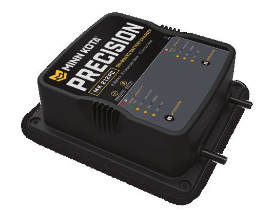
SAFETY CONSIDERATIONS

   Please thoroughly read the user manual. Follow all instructions and heed all safety and cautionary notices. Use of this motor is only
   permitted for persons that have read and understood these user instructions. Minors may use this motor only under adult supervision.

                                                         WARNING
   You are responsible for the safe and prudent operation of your vessel. We have designed your Minn Kota product to be an accurate
   and reliable tool that will enhance boat operation and improve your ability to catch fish. This product does not relieve you from the
   responsibility for safe operation of your boat. You must avoid hazards to navigation and always maintain a permanent watch so you can
   respond to situations as they develop. You must always be prepared to regain manual control of your boat. Learn to operate your Minn
   Kota product in an area free from hazards and obstacles.

                                                         WARNING
   Never run the motor out of the water, as this may result in injuries from the rotating propeller. The motor should be disconnected from
   the power source when it is not in use or is off the water. When connecting the power-supply cables of the motor to the battery, ensure
   that they are not kinked or subject to chafe and route them in such a way that persons cannot trip over them. Before using the motor
   make sure that the insulation of the power cables is not damaged. Disregarding these safety precautions may result in electric shorts
   of battery(s) and/or motor. Always disconnect motor from battery(s) before cleaning or checking the propeller. Avoid submerging the
   complete motor as water may enter the lower unit through control head and shaft. If the motor is used while water is present in the
   lower unit considerable damage to the motor can occur. This damage will not be covered by warranty.

                                                         WARNING
   Take care that neither you nor other persons approach the turning propeller too closely, neither with body parts nor with objects.
   The motor is powerful and may endanger or injure you or others. While the motor is running watch out for persons swimming and for
   floating objects. Persons who lack the ability to run the motor or whose reactions are impaired by alcohol, drugs, medication, or other
   substances are not permitted to use this motor. This motor is not suitable for use in strong currents. The constant noise pressure level
   of the motor during use is less than 70dB(A). The overall vibration level does not exceed 2,5 m/sec2.

                                                         WARNING
   When stowing or deploying the motor, keep fingers clear of all hinge and pivot points and all moving parts. In the event of unexpected
   operation, remove power leads from the battery.

                                                         WARNING
   It is recommended to only use Johnson Outdoors approved accessories with your Minn Kota motor. Using non-approved accessories
   including to mount or control your motor may cause damage, unexpected motor operation and injury. Be sure to use the product and
   approved accessories, including remotes, safely and in the manner directed to avoid accidental or unexpected motor operation. Keep all
   factory installed parts in place including motor and accessory covers, enclosures and guards.

©2021 Johnson Outdoors Marine Electronics, Inc.                                                                             minnkotamotors.com | 3
KNOW YOUR BOAT
Bow
Port Starboard
Inboard
Outboard
Keel
Port Starboard
Gunwale
Transom
Stern
Gunwale
Bow
Stern
Hull
4 | minnkotamotors.com ©2021 Johnson Outdoors Marine Electronics, Inc.INSTALLATION
INSTALLING THE TERROVA
Your new Terrova comes with everything you’ll need to directly install it to the boat. This motor can be directly mounted to the boat or
coupled with a Minn Kota quick release bracket for ease of mounting and removal. For installation with a quick release bracket, refer
to the installation instructions provided with the bracket. For compatible quick release mounting brackets and to locate your nearest
dealer, visit minnkotamotors.com. To install the motor directly to the boat, please follow the instructions provided in this manual. Please
review the parts list, mounting considerations and tools needed for installation prior to getting started. For additional product support,
please visit minnkotamotors.com.
INSTALLATION PARTS LIST
Item /
Part # Description Qty.
Assembly
7
AA 2994864 BAG ASSEMBLY - (BOLT, NUT, WASHERS) 1 8
1 2263462 BOLT-MOUNTING-1/4X2 W/STG 6
11
2 2261713 WASHER-1/4 6
3 2263103 NUT NYLOK 1/4-20 MTG 6
12 13
4 2301720 WASHER-MOUNTING RUBBER 6
5 ✖ MOTOR ASSEMBLY 1
6 LANYARD, REMOTE W/ CARABEENER 1
10
2390800 tÂ
7 2994075 t REMOTE ASY, IPILOT 1
9
p 2397106 t MANUAL, QUICK REF., IPILOT 1.6 1
8 2994076 Â REMOTE ASSEMBLY LINK TOUCHSCREEN 1
9 2373241 Â CABLE, USB REMOTE CHARGER LINK 1 6
10 2375901 Â ADAPTER, USB DC POWER LINK 1
11 2996400 t HEADING SENSOR ASSEMBLY 1
12 490389-1 Â CABLE, ETH (M12-M-M12-F, 30' 1
2211415 Ì CABLE-EXTENSION, PD/AP 110" *PRE-INSTALLED* 1
13
490507-1 â CABLE, ADP-INT MDI 14 M12-120" *PRE-INSTALLED* 1
2092600 PIN-DRIVE 1.06" LG (SS) 1
14
2262658 PIN-DRIVE 1" X 3/16" S/S 1 18
2151726 WASHER-5/16 STD (S/S) 1 FF
15
2091701 WASHER-PROP (LARGE) 1
2053101 NUT-PROP,NYLOC (MED) 5/16 SS 1
16
2093101 NUT-PROP,NYLOC,LG, 3/8 SS 1 EE
2091160 PROP-WW2 (3-5/8") REAMED 1
17 2341160 PROP-WW2 (4.5) W/ADP.RING 1
2331160 PROP-WW2 (4") W/ADP.RING 1 5
BB 1378131 PROP IND 2091160 WDLS WDG II 1 4
CC 1378160 PROP KIT 2341160 112# WW2 1
DD 1378132 PROP IND 233160 WDLS WDG II 1
AA 1
EE 2994722 FT PED ASY, TRV, W/SPOT LCK 1
FF 2994859 BAG, ASY-TERROVA/V2, RUB BUMPERS 1
2
18 2325110 PAD, FOOT PEDAL 5
p 2327132 INSTALLATION INSTRUCTIONS TERROVA 1
3
17
p 2397107 Â MANUAL, QUICK REF., IPILOT LINK 3.0 1 15 16 14
BB
p Not shown on Parts Diagram.
CC
✖ This part is included in an assembly and cannot be ordered individually.
t Only available with models factory installed with i-Pilot. DD
 Only available with models factory installed with i-Pilot Link.
Ì Only available with models factory installed with Universal Sonar.
â Only available with models factory installed with Built-in MEGA Down Imaging.
©2021 Johnson Outdoors Marine Electronics, Inc. minnkotamotors.com | 5Installing the Terrova
MOUNTING CONSIDERATIONS
It is recommended that the motor be mounted as close to the centerline of the boat as
possible. Make sure the area under the mounting location is clear to drill holes and install View accessories
nuts and washers. Make sure the motor rest is positioned far enough beyond the edge of available for your
the boat. The motor must not encounter any obstructions as it is lowered into the water trolling motor at
or raised into the boat when stowed and deployed. Consider a quick release or adapter minnkotamotors.com.
bracket with the installation of your motor. To view a list of accessories, please visit
minnkotamotors.com.
TOOLS AND RESOURCES REQUIRED
• #3 Phillips Screw Driver • 7/16” Box End Wrench
• Drill • A second person to help with
• 9/32” Drill Bit the installation
INSTALLATION
INSTALLING THE TERROVA
1 a. Place the mount on an elevated, level surface such
as a workbench or the tailgate of a pickup. The
1b
motor, as removed from the box, should be in the
stowed position.
b. Remove the four sideplate screws using a #3 Phillips
screwdriver. Two of these screws will be located on
each side of the mount.
NOTICE: This motor weighs approximately 65lbs.
We recommend having a second person help with
the installation.
Sideplate Screw
Stowed
Deployed
6 | minnkotamotors.com ©2021 Johnson Outdoors Marine Electronics, Inc.Installing the Terrova
2 a. Remove the Right Sideplate. 2d
b. Swing the Left Sideplate out and away from the
Base Extrusion.
2c
Base Extrusion
Left Sideplate
Right Sideplate
3 c. Make sure that the Power Cables from the battery
are disconnected, or that the breaker,
Power Cables
if equipped, is "off."
WARNING
Make sure the motor is mounted on a level surface and is
not connected to a power source.
4 d. Place the mount as close to the centerline or keel of
the boat as possible. The motor can be installed on
either the Port or Starboard side of the boat based
on personal preference. Check placement with the
motor in the stowed and deployed positions.
Review the mounting considerations at the
beginning of the installation.
Keel Deck of Boat
©2021 Johnson Outdoors Marine Electronics, Inc. minnkotamotors.com | 7Installing the Terrova
5 ITEM(S) NEEDED
#4 x 6
e. When the motor is in the deployed position, make
sure that the Shaft is 1-1/2" out past the Gunwale of
the boat. The lower unit, when stowed and deployed
must not encounter any obstructions.
f. Check to be sure that the mount is level. Use the
Rubber Washers (Item #4) provided to create a level
surface if necessary. Gunwale
1-1/2"
Minimum
Shaft
6 g. It is recommended to mark at least 4 of the 6 holes
in the Base Extrusion and to have a minimum of
Drilling Locations Base Extrusion
two bolts on each side that are located the farthest
apart. Ideal installation would allow for 6 bolts to be
used, with a minimum of 4.
h. Drill through the deck of the boat using a 9/32" Drill
Bit on the marked locations.
Drilling Locations
8 | minnkotamotors.com ©2021 Johnson Outdoors Marine Electronics, Inc.Installing the Terrova
7 ITEM(S) NEEDED
#2 x 6 #1 x 6 #3 x 6 #4 x 6
a. Put a 1/4-20 x 2" (Item #1) screw in each of the
Screw
drilled locations. The screw should pass through
the Base Extrusion and the boat deck. If the rubber
washers (Item #4) are used, they should sit between
the Base Extrusion and boat deck. Make sure to
secure the motor with screws on each side of the
Base Extrusion.
b. Place a Flat Washer (Item #2) and then a Nylock
Nut (Item #3) at the end of each screw as shown
and secure. Make sure all hardware is secure. Rubber
Washer
NOTICE: To prevent seizing of the stainless steel Nylock Nut Flat Washer Boat Deck
hardware, do not use high speed installation tools.
Wetting the screws or applying an anti-seize may help
prevent seizing.
8 c. Replace the Right Sideplate. 8n
d. Swing the Left Sideplate back into its correct
position on the Base Extrusion.
8m
Base Extrusion
Left Sideplate
Right Sideplate
©2021 Johnson Outdoors Marine Electronics, Inc. minnkotamotors.com | 9Installing the Terrova
9 e. Replace the four sideplate screws using a #3 or
#2 Phillips screwdriver. Two of these screws will be
located on each side of the mount.
Sideplate Screw
10 ITEM(S) NEEDED
#18 x 5 #EE x 1
f. Take the Foot Pedal (Item #EE) and turn it over.
Put a Foot Pedal Pad (Item #18) in each of the
pad locations.
Foot Pedal
Bottom
NOTICE: The pads are recommended when using
the Foot Pedal on non-carpeted surfaces. Foot Pedal
Pad Placement
10 | minnkotamotors.com ©2021 Johnson Outdoors Marine Electronics, Inc.IDENTIFYING TROLLING MOTOR FEATURES BY their associated cables
IDENTIFYING TROLLING MOTOR FEATURES BY THEIR ASSOCIATED CABLES
Your trolling motor may be pre-installed with Built-In MEGA Down Imaging OR Universal Sonar, and may include i-Pilot Link. All of these
features require cables to be connected to an output device. These connections are present on the trolling motor and have cables that exit
below the Control Head. To better identify cables present, refer to the diagrams below that detail what the Built-In MEGA Down Imaging,
Universal Sonar and i-Pilot Link cable connectors look like.
Built-In MEGA Down Imaging Universal Sonar i-Pilot Link
Fourteen Pin Connector
Four Pin Connector Eight Pin Connector
Locking Collar
Built-In MEGA Locking Collar
Down Imaging from Universal Sonar
Control Head Cable from i-Pilot Link Ethernet Cable
Control Head from Control Head
If one connection below the Control Head is present, the motor may be equipped with:
1. i-Pilot and Universal Sonar,
2. i-Pilot and Built-in MEGA Down Imaging, NOTICE: The i-Pilot system does not have an external
3. ONLY Universal Sonar, or wired connection.
4. ONLY Built-in MEGA Down Imaging.
If two connections below the Control Head are present, the motor may be equipped with either:
1. i-Pilot Link and Universal Sonar or
2. i-Pilot Link and Built-in MEGA Down Imaging
One Connection Control Head Two Connections i-Pilot Control Head
Built-in MEGA Link
Down Imaging or
Universal Sonar Built-in MEGA
Down Imaging or
Universal Sonar
Coil Cord
Coil Cord
ROUTING CONNECTION CABLES
Please follow these instructions for routing any and all of the cables present for any of the pre-installed features that may come with your
trolling motor. This routing should be followed whether there are one or two connection cables present. If you are unsure of the cables
present, please review the “Identifying Trolling Motor Features By Their Associated Cables” section of these Installation Instructions.
©2021 Johnson Outdoors Marine Electronics, Inc. minnkotamotors.com | 11ROUTING CONNECTION CABLES
1 a. Place the motor in the deployed position. One Connection
Built-in MEGA
Control Head
b. Locate the Built-in MEGA Down Imaging, i-Pilot Down Imaging or
Universal Sonar
Link and/or Universal Sonar cable(s), at the base of
the Control Head.
Coil Cord
CAUTION
Not following the recommended wire routing for the Built-in
MEGA Down Imaging, i-Pilot Link and/or Universal Sonar Two Connections i-Pilot Control Head
Link
cable(s), if equipped, may cause damage to the product and
void your product warranty. Route cables away from pinch Built-in MEGA
points or other areas that may cause them to bend in sharp Down Imaging or
Universal Sonar
angles. Routing the cables in any way other than directed may
cause damage to the cables by being pinched or severed.
Universal Sonar
Connector
NOTICE: Universal Sonar connector shown for Coil Cord
illustration purposes.
2 c. The cable(s) should be fed all the way through the
Coil Cord. It/they should exit the Coil Cord at the
One Connection
Built-in MEGA
bottom of the Coil Cord, where it connects to the Down Imaging or
Mount. Universal Sonar
Control
Two Connections Head
Control Head
i-Pilot Coil Cord
Link
Built-in MEGA
Down Imaging or
Universal Sonar Mount
Coil
Cord
NOTICE: After the cable(s) exit(s) the Coil Cord, it/they
Mount should be routed through an established routing system on
the boat, in an area with minimal interference. Power cables
or other elements that may produce interference for the
sonar signals. Inspect the selected route carefully to ensure
that there are no sharp edges, obstacles, or obstructions
that may damage the cables.
12 | minnkotamotors.com ©2021 Johnson Outdoors Marine Electronics, Inc.FEATURE OVERVIEW AND CONNECTING THE CABLES
FEATURE OVERVIEW AND CONNECTING THE CABLES
The cable(s) from the Control Head for each feature installed on the trolling motor is connected to an output device separately. Once the
features that may be installed are identified, follow the instructions below to ensure the cables are connected correctly.
Built-In MEGA Down Imaging
Built-In MEGA Down Imaging delivers nearly 3X the output of standard Side Imaging®, and takes fishfinding into the megahertz frequency
for the very first time. The Minn Kota flagship families of trolling motors, including Ultrex, Ulterra, Terrova, and Fortrex, now include
Built-In MEGA Down Imaging sonar, the clearest imaging available only from Humminbird. With Humminbird MEGA imaging sonar built
right into the trolling motor, you now have a crystal clear view of what’s directly beneath the boat, without having to manage all of the
cables that come with external transducers. The Built-In MEGA DI transducer is only available on new models equipped from the factory
and cannot be added to an existing trolling motor.
The Built-in MEGA DI transducer will provide both MEGA Down Imaging and 2D CHIRP Digital Sonar to select Humminbird models. All
Built-In MEGA DI trolling motors, will come “Apex and Solix Ready” out of the box. An adapter cable accessory (MKR-MDI-1 1852085 or
MKR-MDI-2 1852086) is available for purchase that will allow the connection of any compatible Humminbird Helix fish finder. The MKR-
MDI-1 is used on Helix 8, 9, 10, 12 and 15 models. The MKR-MDI-2 is used for Humminbird Helix 7 models only. See the Built-In MEGA
Down Imaging Compatibility chart online.
NOTICE: You can only view Down Imaging with a MEGA DI or MEGA SI HELIX G2N, G3N or G4N Series model and a required
adapter, or with any SOLIX or APEX Series model. The built-in transducer cannot supply MEGA Imaging to Humminbird models
that do not already have the capability. If you have a G2/G2N, G3/G3N HELIX that is not a MEGA SI or MEGA DI model, you will
still get 2D Dual Spectrum CHIRP Sonar from the transducer. SOLIX G1 and HELIX G2 and G2N units need to be running the
latest software update to view sonar from motors with Built-In MEGA Imaging. You can get the latest version of software for your
fish finder on humminbird.com. Built-In MEGA Imaging is not supported by HELIX G1 models or other brands of fish finders.
1 a. Place the motor in the deployed position.
i-Pilot
Control Head
b. The Built-In MEGA Down Imaging connector from the Link
Control Head is a 14 pin connector. Built-In MEGA
Down Imaging may be installed on its own, or in
Built-in MEGA
conjunction with an i-Pilot or i-Pilot Link system. It will Down Imaging
never be installed with Universal Sonar. Locate and
identify the correct connection for Built-in MEGA Down
Imaging cable(s), at the base of the Control Head.
Coil
Cord
NOTICE: Built-in MEGA Down Imaging is always
paired with either i-Pilot or i-Pilot Link on Terrova,
Ulterra and Ultrex motors. It may be pre-installed on
a Fortrex motor without other features that require
external connections.
Mount
Fourteen Pin
Connector NOTICE: Critical cable routing for 60" and 72" motors with
i-Pilot Link and Built-in MEGA Down Imaging. Accessory
Built-in MEGA Down Cables must exit the Coil Cord leaving three or more open
Imaging cable from coils between where the cables exit and the motor base; as
Control Head assembled by the factory. Routing the cables in any other
manner will not allow the motor to stow properly.
©2021 Johnson Outdoors Marine Electronics, Inc. minnkotamotors.com | 13FEATURE OVERVIEW AND CONNECTING THE CABLES
2 c. When installing with a Solix or Apex, the Built-
In MEGA Down Imaging cable can be plugged
Humminbird Solix or Apex Fish Finder
directly into the Solix fish finder. Plug the Built-in
MEGA Down Imaging cable into the corresponding
connection on the Solix fish finder.
d. When installing with a Helix, first attach the Adapter Fourteen Pin Connector Solix/Apex Fish
Cable and then plug the Adapter Cable into the Finder Connection
Helix fish finder. The Adapter Cable will only have Locking Collar
one connection that is keyed on the back of the
Helix fish finder. Plug the Adapter Cable into the Plug directly into
Solix/Apex Fish Finder
only matching keyed connection.
NOTICE: Check for compatibility or any required Built-In MEGA Down Imaging
adapter cables online at minnkotamotors.com. The from Trolling Motor
cable from the trolling motor can be extended with a
10’ Extension Cable #720081-1 or the 30’ Extension
Humminbird Helix Fish Finder
Cable #720081-2 found at humminbird.com.
NOTICE: If any cables need to be routed, please
follow the guidelines in the Routing Connection
Cables section of these installation instructions. Fourteen Pin Connector
Adapter Cable Adapter
Locking Collar (Helix ONLY) Cable Keyed
Connection
Keyed Adapter Cable
for Helix Fish Finder
Built-In MEGA Plug into
Down Imaging from Helix Fish
Trolling Motor Finder
NOTICE: The connectors are keyed to prevent
reversed installation.
14 | minnkotamotors.com ©2021 Johnson Outdoors Marine Electronics, Inc.FEATURE OVERVIEW AND CONNECTING THE CABLES
Universal Sonar
Your trolling motor may be pre-installed with a Universal Sonar transducer system. Universal Sonar is a 2D sonar transducer with a
temperature sensor that is integrated into the lower unit of the trolling motor. It has an operating frequency of 83/200 kHz. Connecting
this transducer to a compatible fish finder gives you a 2D sonar view of what is happening directly below your trolling motor. The
integrated design protects the transducer from underwater hazards, and prevents tangles and damage to the transducer cables.
All Universal Sonar motors are equipped with an internal bonding wire, incorrect rigging will cause sonar interference and can damage
your trolling motor, electronics and other boat accessories. To minimize trolling motor interference, ensure that the fish finder and trolling
motor are powered by separate batteries. Please refer to the Battery & Wiring Installation and Motor Wiring Diagram sections of this
manual for correct rigging instructions.
The Universal Sonar Cables are shielded to minimize interference. To protect this shielding the cables should not be pulled tight against
sharp angles or hard objects. If using cable ties, do not over-tighten. Any excess cable should be bundled in a loose loop of no less than
4” in diameter. In certain situations, air bubbles may adhere to the surface of the Universal Sonar transducer, and effect the performance.
If this happens simply wipe the surface of the transducer with your finger.
NOTICE: Universal Sonar does not support imaging screens that require higher frequencies such as 455 kHz or 800 kHz (Down
Imaging, Side Imaging, etc.). Down Imaging (DI) specific units are not compatible with Universal Sonar. See compatibility chart for
a list of compatible fish finders at minnkotamotors.com.
The connector for Universal Sonar exits the trolling motor below the Control Head and consists of a 4-pin plug. An adapter cable
(MKR-US2) that is sold separately is required for all installations. For a current list of compatible fish finders and the correct adapter
cable, or more information on Universal Sonar, please visit minnkotamotors.com.
1 a. Place the motor in the deployed position.
Control Head
b. Locate the Universal Sonar, if equipped, at the base
of the Mount.
Universal
c. Locate the Universal Sonar four pin connector at Sonar
the end of Universal Sonar Extension Cable. The
connector is black with a stainless steel threaded
locking collar. Coil Cord
NOTICE: Your fish finder should be turned off until
this procedure is complete.
Mount
Four Pin
Connector Universal Sonar
Cable from
Control Head NOTICE: If the cable length does not reach the desired
fish finder installation location, a 14.5’ extension cable is
available (MKR-US2-11) (sold separately).
©2021 Johnson Outdoors Marine Electronics, Inc. minnkotamotors.com | 15FEATURE OVERVIEW AND CONNECTING THE CABLES
2 NOTICE: The Universal Sonar Cable may not be
2d
long enough to reach the fish finder. If the cable
length does not reach the desired fish finder
installation location, a 14.5’ extension cable is Four Pin Connector
available to purchase. Minn Kota recommends
using the MKR-US2-11.
d. Take the Universal Sonar Extension Cable, if
needed, and attach it to the Universal Sonar Cable Locking Collar
exiting the Control Head. Firmly push the plug Universal Sonar Universal Sonar
together and twist the locking collar until it is snug. Cable from Extension Cable
Control Head
e. Install the Universal Sonar Cable that exits the
Control Head or the Universal Sonar Extension
Cable (if used) to the appropriate Universal Sonar NOTICE: The connectors are keyed to prevent
Adapter Cable. Install the Adapter Cable to your fish reversed installation.
finder. Refer to your fish finder manual for complete
installation instructions. 2e
NOTICE: If any cables need to be routed, please
follow the guidelines in the Routing Connection
Cables section of these installation instructions. Locking Collar
Universal Sonar
Universal Sonar Cable from Adapter Cable to
Control Head OR Universal Sonar fish finder
Extension Cable
i-Pilot Link
i-Pilot Link allows your Minn Kota trolling motor and Humminbird to communicate with each other to change the way you fish. i-Pilot Link
delivers a large array of GPS capabilities including controlling speed, steering, Spot-Lock, and the ability to record and retrace paths on
the water, all at your fingertips. To learn more about the GPS capabilities available with your i-Pilot Link navigation system, please refer to
the Owner’s Manual by visiting minnkotamotors.com.
NOTICE: The i-Pilot Link system needs an external wired
The i-Pilot Link remote and controller make up the i-Pilot Link connection. The i-Pilot system does not need an external
navigation system. The i-Pilot Link remote comes paired to the wired connection.
controller from the factory. The i-Pilot Link controller contains a
very sensitive compass and is where all GPS satellite and i-Pilot Link remote signals are received. The i-Pilot Link controller is
contained in the trolling motor Control Head and is connected to a fish finder from a connection cable that exits the Control Head.
The Ethernet cable for the i-Pilot Link system has an 8-pin connector. The i-Pilot Link system can be connected directly to the
Humminbird or to the Humminbird Ethernet Switch (optional). If you purchase an Ethernet Switch, install it using the instructions
included in the Ethernet Installation Guide. The Ethernet Extension Cable is optional for your installation. To purchase Ethernet switches,
Ethernet cables, and extension cables, visit the website humminbird.com or call Humminbird Customer Service at 1-800-633-1468.
Depending on the shape of the Ethernet port on your Humminbird fish finder, an additional ethernet adapter cable (Ethernet Adapter
Cable AS EC QDE #720074-1 for Helix fish finders) may be required for the installation. Refer to your fish finder operations manual or see
the i-Pilot Link Compatibility Chart on our web site with a list of all compatible Humminbird Units and SC Cards.
16 | minnkotamotors.com ©2021 Johnson Outdoors Marine Electronics, Inc.FEATURE OVERVIEW AND CONNECTING THE CABLES
1 a. Place the motor in the deployed position.
i-Pilot
Control Head
b. The i-Pilot Link connector from the Control Head is Link
an 8-pin connector. Locate and identify the correct
connection for i-Pilot Link, at the base of the Built-in MEGA
Down Imaging or
Control Head. Universal Sonar
NOTICE: i-Pilot Link will be paired with either
Built-in MEGA Down Imaging or Universal Sonar Coil
Cord
on Ultrex, Ulterra or Terrova. i-Pilot Link is not a
feature offered on Fortrex motors.
NOTICE: Paired with a Universal Sonar connector
for illustration purposes. A Built-in MEGA Down
Imaging connector may be present instead. Mount
NOTICE: Critical cable routing for 60" and 72" motors with i-Pilot Link and Built-in MEGA Down Imaging. Accessory
Cables must exit the Coil Cord leaving three or more open coils between where the cables exit and the motor base; as
assembled by the factory. Routing the cables in any other manner will not allow the motor to stow properly.
2 ITEM(S) NEEDED
#12 x 1
c. If necessary, to reach the installed fish finder, take
the i-Pilot Link Ethernet Cable (Item #12) and attach
it to the i-Pilot Link cable exiting the Control Head.
Eight-Pin
NOTICE: If any cables need to be routed, please Connector
follow the guidelines in the Routing Connection
Cables section of these installation instructions.
d. Install the i-Pilot Link Ethernet Cable directly into Locking Collar i-Pilot Link Ethernet
i-Pilot Link Ethernet Extension Cable OR
the Humminbird fish finder, or refer to your fish Ethernet Extension Cable
Cable from Control Head
finder installation manual for complete installation
instructions. If an Adapter Cable is needed (Ethernet
Adapter Cable AS EC QDE for Helix fish finders), NOTICE: The connectors are keyed to prevent
install it on the end of the i-Pilot Link Ethernet reversed installation.
Cable and refer to your fish finder installation
manual for complete installation instructions.
©2021 Johnson Outdoors Marine Electronics, Inc. minnkotamotors.com | 17Installing the Prop
INSTALLING THE PROP
1 ITEM(S) NEEDED
#17 x 1 #15 x 1 #16 x 1 #14 x 1
CAUTION 1a
Drive Pin Armature Shaft
Disconnect the motor from the battery before beginning any
prop work.
Propeller
a. Take the Drive Pin (Item #14) and slide it through
the Hole in the Armature Shaft. Position the Drive Prop Washer
Pin horizontal by grasping the Armature Shaft and Prop Nut
rotating it with the Drive Pin in place.
b. Align the Propeller (Item #17) so it is also horizontal
1b
Propeller
and parallel with the Drive Pin. Slide the Propeller
onto the Armature Shaft and Drive Pin until it is
seated against the lower unit.
c. Install the Prop Washer (Item #15) and the Prop
Nut (Item #16) onto the end of the Armature Shaft.
d. Holding the end of the Armature Shaft with a Flat
Blade Screwdriver, tighten the Prop Nut with a 9/16" 1d
Open End Wrench.
e. Tighten the Prop Nut 1/4 turn past snug to 25-35 Prop Nut
in-lbs.
Prop Washer
CAUTION Propeller
Drive Pin
Do not over tighten as this can damage the prop.
18 | minnkotamotors.com ©2021 Johnson Outdoors Marine Electronics, Inc.BATTERY & WIRING INSTALLATION
BOAT RIGGING & PRODUCT INSTALLATION
For safety and compliance reasons, we recommend that you follow American Boat and Yacht Council (ABYC) standards when rigging
your boat. Altering boat wiring should be completed by a qualified marine technician. The following specifications are for general
guidelines only:
CAUTION
These guidelines apply to general rigging to support your Minn Kota motor. Powering multiple motors or additional electrical devices
from the same power circuit may impact the recommended conductor gauge and circuit breaker size. If you are using wire longer than
that provided with your unit, follow the conductor gauge and circuit breaker sizing table below. If your wire extension length is more
than 25 feet, we recommend that you contact a qualified marine technician.
CAUTION
An over-current protection device (circuit breaker or fuse) must be used. Coast Guard requirements dictate that each ungrounded
current-carrying conductor must be protected by a manually reset, trip-free circuit breaker or fuse. The type (voltage and current rating)
of the fuse or circuit breaker must be sized accordingly to the trolling motor used. The table below gives recommended guidelines for
circuit breaker sizing.
CONDUCTOR GAUGE AND CIRCUIT BREAKER SIZING TABLE
This conductor and circuit breaker sizing table is only valid for the following assumptions:
1. No more than 2 conductors are bundled together inside of a sheath or conduit outside of engine spaces.
2. Each conductor has 105° C temp rated insulation.
3. No more than 5% voltage drop allowed at full motor power based on published product power requirements.
Max Wire Extension Length
Motor Thrust / Model Circuit Breaker
Amp Draw
5 feet 10 feet 15 feet 20 feet 25 feet
30 lb. 30 10 AWG 10 AWG 8 AWG 6 AWG 4 AWG
50 Amp @ 12 VDC
40 lb., 45 lb. 42 10 AWG 8 AWG 6 AWG 4 AWG 4 AWG
50 lb., 55 lb. 50 60 Amp @ 12 VDC 8 AWG 6 AWG 4 AWG 4 AWG 2 AWG
70 lb. 42 50 Amp @ 24 VDC 10 AWG 10 AWG 8 AWG 8 AWG 6 AWG
80 lb. 56 60 Amp @ 24 VDC 8 AWG 8 AWG 8 AWG 6 AWG 6 AWG
101 lb. 46 50 Amp @ 36 VDC 8 AWG 8 AWG 8 AWG 8 AWG 8 AWG
Engine Mount 101 50 60 Amp @ 36 VDC 8 AWG 8 AWG 8 AWG 8 AWG 8 AWG
112 lb. 52 60 Amp @ 36 VDC 8 AWG 8 AWG 8 AWG 8 AWG 8 AWG
Engine Mount 160 116 (2) x 60 Amp @ 24 VDC 6 AWG 6 AWG 4 AWG 2 AWG 2 AWG
E-Drive 40 50 Amp @ 48 VDC 10 AWG 10 AWG 10 AWG 10 AWG 10 AWG
NOTICE: Wire Extension Length refers to the distance from the batteries to the trolling motor leads. Consult website for
available thrust options. Maximum Amp Draw values only occur intermittently during select conditions and should not be used as
continuous amp load ratings.
Reference
United States Code of Federal Regulations: 33 CFR 183 – Boats and Associated Equipment ABYC E-11: AC and DC Electrical Systems on Boats
©2021 Johnson Outdoors Marine Electronics, Inc. minnkotamotors.com | 19Selecting the Correct Batteries
SELECTING THE CORRECT BATTERIES
The motor will operate with any lead acid, deep cycle marine 12-volt battery/batteries. For best results, use a deep cycle, marine
battery with at least a 105 amp-hour rating. Maintain battery at full charge. Proper care will ensure having battery power when you
need it, and will significantly improve the battery life. Failure to recharge lead-acid batteries (within 12-24 hours) is the leading cause
of premature battery failure. Use a multi-stage charger to avoid overcharging. We offer a wide selection of chargers to fit your charging
needs. If you are using a crank battery to start a gasoline outboard, we recommend that you use a separate deep cycle marine battery/
batteries for your Minn Kota trolling motor. For more information on battery selection and rigging, please visit minnkotamotors.com.
Minn Kota trolling motors can run on Lithium Ion batteries. However, they are specifically designed to run on traditional lead acid
batteries (flooded, AMG or GEL). Lithium Ion batteries maintain higher voltages for longer periods of time than lead acid. Therefore,
running a Minn Kota trolling motor at speeds higher than 85% for a prolonged period could cause permanent damage to the motor.
WARNING
Never connect the (+) and the (–) terminals of the same battery together. Take care that no metal object can fall onto the battery and
short the terminals. This would immediately lead to a short and extreme fire danger.
CAUTION
Refer to “Conductor Gauge and Circuit Breaker Sizing Table” in the previous section to find the appropriate circuit breaker or fuse for
your motor. For motors requiring a 60-amp breaker, the Minn Kota MKR-19 60-amp circuit breaker is recommended.
CAUTION
Please read the following information before connecting your motor to your batteries in order to avoid damaging your motor and/or
voiding your warranty.
ADDITIONAL CONSIDERATIONS
Using Alternator Chargers
Your Minn Kota trolling motor may be designed with an internal bonding wire to reduce sonar interference. Most alternator charging
systems do not account for this bonding wire, and connect the negative posts of the trolling motor batteries to the negative posts of the
crank/starting battery. These external connections can damage connected electronics and the electrical system of your trolling motor,
voiding your warranty. Review your charger’s manual carefully or consult the manufacturer prior to use to ensure your charger is compatible.
Minn Kota recommends using Minn Kota brand chargers to recharge the batteries connected to your Minn Kota trolling motor, as they
have been engineered to work with motors that include a bonding wire.
20 | minnkotamotors.com ©2021 Johnson Outdoors Marine Electronics, Inc.Connecting the Batteries
Additional Accessories Connected to Trolling Motor Batteries
Significant damage to your Minn Kota motor, your boat electronics, and your boat can occur if incorrect connections are made between
your trolling motor batteries and other battery systems. Minn Kota recommends using an exclusive battery system for your trolling
motor. Where possible, accessories should be connected to a separate battery system. Radios and sonar units should not be connected
to any trolling motor battery systems as interference from the trolling motor is unavoidable. If connecting any additional accessories to
any trolling motor battery system, or making connections between the trolling motor batteries and other battery systems on the boat, be
sure to carefully observe the information below.
The negative (-) connection must be connected to the negative terminal of the same battery that the trolling motor negative lead
connects to. In the diagrams below this battery is labeled “Low Side” Battery. Connecting to any other trolling motor battery will input
positive voltage into the “ground” of that accessory, which can cause excess corrosion. Any damage caused by incorrect connections
between battery systems will not be covered under warranty.
Automatic Jump Start Systems and Selector Switches
Automatic jump start systems and selector switches tie the negatives of the connected batteries together. Connecting these systems
to the “High Side” Battery or “Middle” Battery in the diagrams below and will cause significant damage to your trolling motor and
electronics. The only trolling motor battery that is safe to connect to one of these systems is the “Low Side” Battery.
NOTICE: The internal bonding wire is equipped with a 3 amp fuse. Improper connections described above carrying in excess of
3 amps will blow this fuse and no further damage will be exhibited. If this occurs, RF interference from the trolling motor affecting
sonar units and other electronics will be more significant. If the fuse is blown the wiring error should be found and addressed prior
to replacing the fuse. The replacement fuse should be 3 amps or less. An intact fuse does not imply correct rigging; significant
damage can be done by incorrect wiring without approaching 3 amps of current.
CONNECTING THE BATTERIES
12-Volt Systems
1. Make sure that the motor is switched off (speed selector on “OFF” or “0”).
2. Connect positive ( + ) red lead to positive ( + ) battery terminal.
3. Connect negative ( – ) black lead to negative ( – ) battery terminal.
WARNING
For safety reasons do not switch the motor on until the propeller is in the water. If installing a leadwire plug, observe proper polarity
and follow instructions in your boat owner’s manual.
©2021 Johnson Outdoors Marine Electronics, Inc. minnkotamotors.com | 21Connecting the Batteries in Series
CONNECTING THE BATTERIES IN SERIES
(IF REQUIRED FOR YOUR MOTOR)
24-Volt Systems
Two 12-volt batteries are required. The batteries must be wired in +24 Volts to trolling motor
series, only as directed in the wiring diagram, to provide 24 volts. To trolling motor negative positive (or circuit breaker)
1. Make sure that the motor is switched off
24 Volt Series Connection
(speed selector on “0”).
2. Connect a connector cable to the positive ( + ) terminal of
battery 1 and to the negative ( – ) terminal of battery 2.
3. Connect positive ( + ) red motor lead to positive ( + ) terminal Neg - Pos + Neg - Pos +
on battery 2. Battery #1 Battery #2
4. Connect negative ( – ) black motor lead to negative ( – ) (Low Side) (High Side)
terminal of battery 1. Two 12-volt batteries connected in series for 24 volts
WARNING
For safety reasons do not switch the motor on until the propeller is in the water. If installing a leadwire plug, observe proper polarity
and follow instructions in your boat owner’s manual.
WARNING
• For safety
safety reasons,
reasons,disconnect
disconnectthe
themotor
motorfrom
fromthe
thebattery
batteryororbatteries
batterieswhen
whenthe motor
the is is
motor notnot
in in
use or or
use while thethe
while battery/batteries are
battery/batteries
being charged.
are being charged.
• Improper wiring of 24/36 volt systems could cause battery explosion.
• Improper wiring of 24/36 volt systems could cause battery explosion.
• Keep leadwire wing nut connections tight and solid to battery terminals.
• Keep leadwire wing nut connections tight and solid to battery terminals.
• Locate battery in a ventilated compartment.
• Locate battery in a ventilated compartment.
22 | minnkotamotors.com ©2021 Johnson Outdoors Marine Electronics, Inc.Connecting the Batteries in Series
36-Volt Systems
Three 12-volt batteries are required. The batteries must be wired in series, only as directed in the wiring diagram, to provide 36 volts.
1. Make sure that the motor is switched
+36 Volts to trolling motor
off (speed selector on “0”).
To trolling motor negative positive (or circuit breaker)
2. Connect a connector cable to the
positive ( + ) terminal of battery 1 and 24 Volt Series Connection 36 Volt Series Connection
to the negative ( – ) terminal of battery 2
and another connector cable from the
positive ( + ) terminal of battery 2 to the
Neg - Pos + Neg - Pos + Neg - Pos +
negative ( – ) terminal of battery of battery 3.
3. Connect positive ( + ) red motor lead Battery #1 (Low Side) Battery #2 (Middle) Battery #3 (High Side)
to positive ( + ) terminal on battery 3.
Three 12-volt batteries connected in series for 36 volts
4. Connect negative ( – ) black motor lead to
negative ( – ) terminal of battery 1.
WARNING
For safety reasons, do not switch the motor on until the propeller is in the water. If installing a leadwire plug, observe proper polarity
and follow instructions in your boat owner’s manual.
WARNING
• For safety reasons, disconnect the motor from the battery or batteries when the motor is not in use or while the battery/batteries
are being charged.
• Improper wiring of 24/36 volt systems could cause battery explosion.
• Keep leadwire wing nut connections tight and solid to battery terminals.
• Locate battery in a ventilated compartment.
This completes the installation of your Terrova. A complete Owner’s Manual can
be downloaded at minnkotamotors.com.
©2021 Johnson Outdoors Marine Electronics, Inc. minnkotamotors.com | 23RECOMMENDED ACCESSORIES
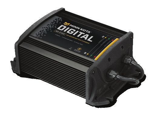
ON-BOARD & PORTABLE BATTERY CHARGERS
Stop buying new batteries and start taking care of the ones you’ve got. Many chargers can actually damage your
battery over time – creating shorter run times and shorter overall life. Digitally controlled Minn Kota chargers are
designed to provide the fastest charge that protect and extend battery life.
MK212PC MK210D MK110PD
TALON SHALLOW WATER ANCHOR
Introducing the all-new, sleek redesigned Talon. Talon is the only shallow water anchor with up to 15’ of anchoring
depth, multiple anchoring modes, and control from the bow, transom, console, remote or mobile device.
BUILT-IN UP TO 15’ DEEP
WORK LIGHT Control more water and catch
Lets you tie lines and work from more fish with the first 15’
the transom any time of day — shallow water anchor.
or night. Includes both white
and blue LED lights with three MORE CONTROL
brightness settings. OPTIONS
• Control Panel
BLUETOOTH ® • Wireless Remote
CONNECTIVIT Y • Mobile App
Lets you control Talon from your • Wireless Foot Switch
mobile device and easily update • Humminbird® Connectivity
it. Also opens up communication • i-Pilot® &
to other control options. i-Pilot LinkTM Remote
MINN KOTA ACCESSORIES
We offer a wide variety of trolling motor accessories, including:
• 60-Amp Circuit Breaker • Battery Connectors
• Mounting Brackets • Battery Boxes
• Stabilizer Kits • Quick Connect Plugs
• Extension Handles
Minn Kota Consumer & Technical Service 121 Power Drive
Johnson Outdoors Marine Electronics, Inc. Mankato, MN 56001
PO Box 8129 Phone (800) 227-6433 ©2021 Johnson Outdoors Marine Electronics, Inc.
minnkotamotors.com Mankato, MN 56001 Fax (800) 527-4464 All rights reserved.
Part #2327132 ECN 41448 Rev H 08/21TERROVA
PROPULSEUR ÉLECTRIQUE MONTÉ SUR L’ÉTRAVE
Instructions d’InstallationINTRODUCTION
MERCI
Nous vous remercions d’avoir choisi Minn Kota. Nous sommes persuadés que vous devriez consacrer plus de temps à pêcher et
moins de temps à amarrer votre embarcation. C’est pourquoi nous construisons les propulseurs électriques les plus intelligents, les
plus solides et les plus faciles à utiliser. Chaque aspect d’un propulseur électrique Minn Kota est réfléchi et étudié jusqu’à ce qu’il
soit digne de porter notre nom. Nous avons investi des heures incalculables de recherche et d’essais pour vous offrir les avantages
caractéristiques de Minn Kota, qui vous mène vraiment « n’importe où, et n’importe quand. » Notre principe est simple, nous faisons
les choses selon les règles. Nous sommes Minn Kota. Et nous ne cesserons jamais de vous aider à pêcher plus de poissons.
ENREGISTREMENT
N’oubliez pas de conserver votre reçu et d’enregistrer
immédiatement votre propulseur électrique. Une fiche
d’enregistrement est fournie avec votre moteur; vous pouvez
également effectuer l’enregistrement sur notre site Web à
minnkotamotors.com.
NUMÉRO DE SÉRIE
Le numéro de série à 11 caractères Minn Kota est très
important. Cela permet de déterminer le modèle spécifique et
l’année de fabrication. Lorsque vous contactez le Service à la
clientèle ou que vous enregistrez votre article, vous aurez besoin Made by Minn Kota
Johnson Outdoors
TERROVA 55-54"_BT 12V DC
du numéro de série de votre article. Nous vous suggérons de Marine Electronics, Inc.
121 Power Drive
MODEL 1358803 56 A
Mankato, MN 56001 USA
noter le numéro de série afin qu’il soit disponible à des fins de Trolling Motors
Produced in 2012
SER NO R365 MK12345
référence future.
EXEMPLE
AVIS : Le numéro de série de votre Terrova se trouve sous
la barre d’inclinaison.
INFORMATIONS SUR LE MOTEUR (À des fins de Référence par le Client Seulement)
Modèle:__________________________________________________________________________________________________________________
Numéro de Série:_________________________________________________________________________________________________________
Date de l’achat:___________________________________________________________________________________________________________
Magasin où l’achat a été effectué:___________________________________________________________________________________________
AVIS : Ne retournez pas votre moteur Minn Kota au détaillant. Le détaillant n’est pas autorisé à réparer ou à remplacer cet
appareil. Pour le service : communiquer avec Minn Kota au (800) 227-6433; retourner le moteur au Centre de service de l’usine
de Minn Kota; envoyer ou apporter le moteur à un centre de service agréé de Minn Kota. Une liste de centres de service agréés est
disponible sur notre site Web, à minnkotamotors.com. Pour obtenir un service au titre de la garantie, y compris toutes les options
susmentionnées, veuillez inclure la preuve d’achat, le numéro de série et la date de l’achat.
26 | minnkotamotors.com ©2021 Johnson Outdoors Marine Electronics, Inc.CONSIGNES DE SÉCURITÉ
Veuillez lire attentivement le manuel de l’utilisateur. Suivez toutes les instructions et respectez toutes les consignes de sécurité et mises
en garde. L’utilisation de ce moteur n’est autorisée que pour les personnes qui ont lu et compris ces consignes pour l’utilisateur. Les
personnes mineures peuvent utiliser ce moteur uniquement sous la supervision d’un adulte.
AVERTISSEMENT
Vous seul êtes responsable de la navigation sécuritaire et prudente sur votre bateau. Nous avons conçu votre Minn Kota pour qu’il soit
un outil précis et fiable qui vous permettra d’améliorer l’utilisation de votre bateau et d’accroître votre capacité de pêcher des poissons.
Ce produit ne vous exonère pas de la responsabilité de naviguer en toute sécurité avec votre bateau. Vous devez éviter les dangers liés
à la navigation et toujours exercer une veille permanente afin de pouvoir réagir au fur et à mesure que les situations se présentent. Vous
devez toujours être prêt à reprendre le contrôle manuel de votre bateau. Apprenez à utiliser votre Minn Kota dans une zone exempte de
dangers et d’obstacles.
AVERTISSEMENT
Ne faites jamais fonctionner le moteur hors de l’eau, puisque cela entraînerait des blessures causées par l’hélice en rotation. Le moteur
doit être débranché de la source d’alimentation lorsqu’il n’est pas utilisé ou lorsqu’il est hors de l’eau. Au moment de brancher les câbles
d’alimentation du moteur à la batterie, veiller à ce qu’ils ne soient pas entortillés ou exposés au frottement, puis les placer de telle manière
que personne ne risque de trébucher. Avant d’utiliser le moteur, s’assurer que l’isolant des câbles d’alimentation n’est pas endommagé.
Ne pas tenir compte de ces mesures de sécurité peut entraîner des courts-circuits avec les batteries et/ou le moteur. Toujours débrancher
le moteur des batteries avant le nettoyage ou la vérification de l’hélice. Éviter de submerger complètement le moteur, car l’eau pourrait
pénétrer dans l’appareil inférieur par la tête de contrôle et l’arbre. Si le moteur est utilisé alors que de l’eau est présente dans l’appareil
inférieur, ce dernier pourrait subir des dommages considérables. Ces dommages ne seront pas couverts par la garantie.
AVERTISSEMENT
Veillez à ce que ni vous ni d’autres personnes ne vous approchiez trop près de l’hélice en rotation, que ce soit seulement avec une
partie du corps ou des objets. Le moteur est puissant et pourrait provoquer des situations périlleuses ou des blessures, pour vous ou
les autres. Lorsque le moteur est en marche, se méfier des objets flottants ou des personnes qui pourraient être en train de nager. Les
personnes, dont les réactions ou la capacité à faire fonctionner le moteur est/sont affaiblie(s) par l’alcool, la drogue, les médicaments
ou d’autres substances, ne sont pas autorisées à utiliser ce moteur. Ce moteur n’est pas adapté à l’utilisation dans de forts courants. Le
niveau de pression sonore constant du moteur au moment de l’utilisation est inférieur à 70 dB (A). Le niveau de vibration général ne
dépasse pas 8,2 pi/s² (2,5 m/s²).
AVERTISSEMENT
Lorsque vous remontez ou abaissez le moteur, gardez vos doigts loin de toutes charnières et tous points de pivot ainsi que de toutes
pièces mobiles. En cas d’opération imprévue, retirez les câbles d’alimentation à la batterie.
AVERTISSEMENT
Il est recommandé d’utiliser exclusivement les accessoires approuvés par Johnson Outdoors avec votre moteur Minn Kota. L’utilisation
d’accessoires non approuvés, y compris pour monter ou contrôler votre moteur, pourrait causer des dommages, un fonctionnement
inattendu du moteur et des blessures. Veillez à utiliser le produit ainsi que les accessoires approuvés, y compris les télécommandes, en
toute sécurité et de la manière indiquée pour éviter les accidents ou un fonctionnement inattendu du moteur. Ne retirez pas les pièces
installées en usine, y compris les couvercles, boîtiers et protections du moteur et des accessoires.
©2021 Johnson Outdoors Marine Electronics, Inc. minnkotamotors.com | 27CONNAISSEZ VOTRE BATEAU
Étrave
Bâbord Tribord
En-bord
Hors-bord
Quille
Bâbord Tribord
Plat-bord
Tableau Arrière
Stern
Plat-bord
Étrave
Poupe
Coque
28 | minnkotamotors.com ©2021 Johnson Outdoors Marine Electronics, Inc.INSTALLATION
INSTALLATION DU TERROVA
Votre nouveau Terrova est offert avec tout ce dont vous aurez besoin pour le montage direct au bateau. Ce moteur peut être monté
directement sur le bateau ou couplé avec un support à dégagement rapide Minn Kota pour un montage et un démontage simples. Pour
l’installation avec un support à dégagement rapide, vous reporter aux directives d’installation fournies avec le support. Pour obtenir des
supports de montage à dégagement rapide compatibles ou pour trouver votre concessionnaire le plus près, visitez minnkotamotors.com.
Pour installer le moteur directement sur le bateau, veuillez suivre les directives fournies avec ce manuel. Avant de commencer, veuillez
examiner la liste des pièces et des outils nécessaires à l’installation. Pour davantage de soutien pour les produits, veuillez visiter
minnkotamotors.com.
LISTE DE PIÈCES D’INSTALLATION
Article/ Nº de Pièce Description Qté.
Assemblage 7
AA 2994864 BAG ASSEMBLY - (BOLT, NUT, WASHERS) 1 8
1 2263462 BOLT-MOUNTING-1/4X2 W/STG 6
11
2 2261713 WASHER-1/4 6
3 2263103 NUT NYLOK 1/4-20 MTG 6
12 13
4 2301720 WASHER-MOUNTING RUBBER 6
5 ✖ MOTOR ASSEMBLY 1
10
6 2390800 t LANYARD, REMOTE W/ CARABEENER 1
7 2994075 t REMOTE ASY, IPILOT 1
9
p 2397106 t MANUAL, QUICK REF., IPILOT 1.6 1
8 2994076 Â REMOTE ASSEMBLY LINK TOUCHSCREEN 1
9 2373241 Â CABLE, USB REMOTE CHARGER LINK 1 6
10 2375901 Â ADAPTER, USB DC POWER LINK 1
11 2996400 t HEADING SENSOR ASSEMBLY 1
12 490389-1 Â CABLE, ETH (M12-M-M12-F, 30' 1
13 2211415 CABLE-EXTENSION, PD/AP 110" 1
2092600 PIN-DRIVE 1.06" LG (SS) 1
14
2262658 PIN-DRIVE 1" X 3/16" S/S 1
2151726 WASHER-5/16 STD (S/S) 1
15 18
2091701 WASHER-PROP (LARGE) 1
2053101 NUT-PROP,NYLOC (MED) 5/16 SS 1 FF
16
2093101 NUT-PROP,NYLOC,LG, 3/8 SS 1
2091160 PROP-WW2 (3-5/8") REAMED 1
EE
17 2341160 PROP-WW2 (4.5) W/ADP.RING 1
2331160 PROP-WW2 (4") W/ADP.RING 1
BB 1378131 PROP IND 2091160 WDLS WDG II 1
5
CC 1378160 PROP KIT 2341160 112# WW2 1
4
DD 1378132 PROP IND 233160 WDLS WDG II 1
EE 2994722 FT PED ASY, TRV, W/SPOT LCK 1
FF 2994859 BAG, ASY-TERROVA/V2, RUB BUMPERS 1 AA 1
18 2325110 PAD, FOOT PEDAL 5
p 2327132 INSTALLATION INSTRUCTIONS TERROVA 1 2
p 2397107 Â MANUAL, QUICK REF., IPILOT LINK 3.0 1
3
17
p Non visible sur le schéma des pièces. 15 16 14
✖ Cette pièce est incluse dans un ensemble et ne peut pas être commandée BB
individuellement.
t Uniquement disponible avec les modèles possédant un système i-Pilot installé en usine. CC
 Uniquement disponible avec les modèles possédant un i-Pilot Link installé en usine.
Ì Uniquement disponible avec les modèles possédant un Universal Sonar installé en usine. DD
â Uniquement disponible avec les modèles possédant un système MEGA Down Imaging
intégré installé en usine.
©2021 Johnson Outdoors Marine Electronics, Inc. minnkotamotors.com | 29You can also read