Generation Interconnection Facilities Study Report for PJM Generation Interconnection Request Queue Position AE2-042 Milton 69 kV 46.8 MW Capacity ...
←
→
Page content transcription
If your browser does not render page correctly, please read the page content below
Generation Interconnection
        Facilities Study Report

                 for

PJM Generation Interconnection Request
      Queue Position AE2-042

             Milton 69 kV

  46.8 MW Capacity / 70.0 MW Energy

                                   May 2021
General
This Facilities Study has been prepared in accordance with the PJM Open Access Transmission
Tariff §207, as well as the Facilities Study Agreement between Northumberland Solar I, LLC as
the Interconnection Customer (IC) and PJM Interconnection, LLC as the Transmission Provider
(TP). The Interconnected Transmission Owner (TO) is PPL Electric Utilities Corporation (PPL
EU).
The IC has proposed a solar generating facility located in Northumberland County, Pennsylvania.
The installed facilities will have a total capability of 70.0 MW with 46.8 MW of this output being
recognized by PJM as capacity. The requested in-service date in the AE2-042 Attachment N is
June 30, 2022. However, the revised in-service date to account for the Transmission Owner’s 16
month construction schedule is March 24, 2023. This study does not imply a PPL EU
commitment to this in-service date.
Point of Interconnection
AE2-042 will interconnect with the PPL EU Transmission System via an existing breaker position
in Bay 14 of the Milton 69 kV substation. The Point of Interconnection (POI) will be where the
IC’s generator lead line attaches to the PPL EU line tap termination structure.
Bay 14 at Milton 69 kV is currently occupied by the Danville-Milton 69 kV line. However,
this is being retired and rebuilt in a different location as a part of PPL EU Supplemental
Project s0969.2. This report assumes the Danville-Milton 69 kV line will be retired prior to
the interconnection of AE2-042.
Cost Summary
AE2-042 will be responsible for the following estimated costs:
Description Total Cost
Attachment Facilities $ 354,716
Direct Connection Network Upgrades $0
Non-Direct Connection Network Upgrades $ 929,428
Allocation for New System Upgrades $0
Contribution to Previously Identified Upgrades $0
Total Cost $ 1,284,144
These estimates are applicable based on the assumptions listed in Section 8 of this report. The
estimate also excludes any applicable state or federal taxes. If at a future date Federal CIAC
(Contribution In Aid of Construction) payments are deemed necessary by the IRS or other
governing taxing authority for this project, both PJM and PPL EU shall be reimbursed by the IC
for such payments.
© PJM Interconnection 2021. All rights reserved. 2 Queue AE2-042 Milton 69 kVA. Transmission Owner Facilities Study Summary
1. Description of Project
AE2-042 is requesting to connect a new 70.0 MW solar generating facility in Northumberland
County, Pennsylvania. The scope of work includes all necessary Network Upgrades and
Attachment Facilities required to connect the new generation to the PPL EU Transmission System.
Attachment Facility and Network Upgrade construction is estimated to be 16 months. The
Interconnection Customers requested in-service date is November 28, 2022. However, the revised
in-service date to account for the Transmission Owners 16 month construction schedule is March
24, 2023. This study does not imply a PPL EU commitment to this in-service date.
2. Amendments to the System Impact Study data or System Impact Study
Results
None.
3. Stability Analysis Results
The reactive power assessment identified deficiencies. Additional capacitive (lagging) reactive
power, estimated at 17.16 MVAR is required to fulfill the power factor requirement.
4. Interconnection Customer’s Submitted Milestone Schedule
Substantial site work Completed: July 15, 2022
Delivery of major electrical equipment: August 31, 2022
Commercial Operation: November 28, 2022
Note: The Interconnection Customer submitted a milestone schedule and requested a commercial
operation date of November 28, 2022. However, the revised in-service date included in the AE2-
042 ISA and CSA to account for the Transmission Owner’s 16 month construction schedule is
March 24, 2023.
5. Scope of Customer’s Work
The IC is installing a 70.0 MW solar generating facility consisting of:
Twenty-seven (27) 2.75 MVA SMA central inverters
One (1) 45/60/75 MVA 69/34.5/13.8 kV grounded wye/grounded wye/delta Generator
Step Up transformer (GSU)
One (1) fully rated, fault-interrupting circuit breaker on the high-side of the GSU
The IC will construct a generator lead line with Optical Ground Wire (OPGW) from the IC
substation to the POI at the PPL EU owned termination structure. The IC will terminate the OPGW
into PPL EU’s fiber splice box at this structure. The IC must follow all interconnection
requirements, including but not limited to protection and control requirements at the IC substation.
© PJM Interconnection 2021. All rights reserved. 3 Queue AE2-042 Milton 69 kVThe IC will own and operate the revenue metering in the IC substation between the collector bus
and the incoming generator lead line.
The IC will be responsible for all site preparation for the Attachment Facilities, including but not
limited to, acquiring all rights-of-way, easements, and acquiring environmental and local permits.
PPL EU requires a 100 ft. width easement for the 69 kV Attachment Facilities.
The IC will follow PJM telemetry requirements to send real time, generation data to PJM. PPL EU
will obtain this data directly from PJM. PPL EU will work with PJM and the IC to ensure the
generation data provided to PJM meets PPL EU’s needs. The IC must also install the applicable
relaying facilities at the IC substation consistent with PPL EU requirements.
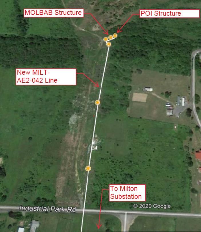
6. Description of Facilities Included in the Facilities Study
PPL EU will construct a new 69 kV circuit, extending from Bay 14 in the Milton 69 kV
substation to the POI. The new circuit will run approximately 0.35 miles north as double circuit
on the same structures as the Milton-Millville 69 kV line. PPL EU will construct a short line tap
with a SCADA controlled, Motor Operated Load Break Air Break Switch (MOLBAB).
PPL EU will modify the Milton 69 kV substation to accommodate the new circuit.
7. Total Costs of Transmission Owner Facilities included in Facilities Study
Work Description Total Cost
Attachment Facilities (N7242.1)
69 kV Tap line, MOLBAB Switch, Poles, structure $354,716
and foundations
Total Attachment Facilities Cost $354,716
Direct Network Upgrade $0
Total Direct Network Upgrade Costs $0
Non-Direct Network Upgrade
Add a second circuit (Milton – AE2-042 69 kV) to the
Milton-Millville 69 kV line structures and perform
$644,681
modifications to the new Milton – AE2-042 69 kV
circuit to tie in the AE2-042 Attachment Facilities
(N7242.2)
Non-Direct Network Upgrade
Milton 69 kV Substation Relay Modifications $284,747
(N7242.3)
Total Non-Direct Network Upgrade Costs $929,428
Total Network Upgrades $929,428
© PJM Interconnection 2021. All rights reserved. 4 Queue AE2-042 Milton 69 kVTotal Project Costs $1,284,144
The estimated costs above are based on risks and assumptions listed in Section 8.
8. Summary of Milestone Schedules for Completion of Work Included in
Facilities Study:
The estimated duration for the completion of the PPL EU scope of work is 16 months after the
ISA and ICSA are signed, and the Construction Implementation Kick-off Meeting is held. These
durations are based on the risks and assumptions listed in Section 9.
Activity Start Month End Month Duration
Preliminary Engineering 1 1 1
Detailed Engineering 1 8 7
Construction Planning 8 12 4
Construction & Backfeed 12 16 4
9. Project Risks and Assumptions
The following assumption were made in preparing this Facilities Study:
There are no major environmental, geotechnical, real estate, or permitting issues.
There is no cost to PPL EU for easements and real estate acquisition.
The IC will obtain all permits and approvals necessary for PPL EU owned Attachment
Facilities.
The IC will perform all site preparation for the Attachment Facilities.
Suitable line/equipment outages can be scheduled as required. Failure to meet a scheduled
facility outage may result in project delays.
In the event of operational, governmental, and/or environmental regulatory delays, the use
of additional resources, such as overtime, premiums for expedited material, and/or
contractor labor, may enable PPL EU to decrease the estimated construction period.
However, no guarantees can be made.
The ISA/ICSA must be fully executed by the IC, PJM, and PPL EU, and the construction
implementation meeting kick-off meeting must be held before PPL EU design and
construction activities may commence.
Cost estimates are based on conditions when the study is performed and are subject to
change based on many factors, including but not limited to, union labor rates and
commodity pricing.
PPL EU Supplemental Project s1033 to rebuild the Milton-Millville 69 kV line is
completed prior to the AE2-042 interconnection.
PPL EU Supplemental Project s0969.2 is complete prior to the AE2-042
interconnection.
© PJM Interconnection 2021. All rights reserved. 5 Queue AE2-042 Milton 69 kVB. Transmission Owner Facilities Study Results
1. Transmission Lines – New
Attachment Facilities
PJM Network Upgrade Number N7242.1
69 kV Line Tap
PPL EU will tap the new Milton – AE2-042 69 kV line near GPS Coordinates 40.986248°, -
76.832688° and extend the tap towards the IC substation by completing the following:
Install a new single circuit, angle tension, monopole, custom steel/foundation structure at
the tap point on the new Milton – AE2-042 line
Install a single circuit, direct-embed, steel, structure with a SCADA controlled MOLBAB
Install a new single circuit, custom foundation, steel, full terminal tension structure (POI)
Install 556 24/7 ACSR 3-phase conductors with 48-ct OPGW on the tap to the POI
Install three (3) fiber splice boxes, one on the terminal POI structure, and the other two on
the new Milton – AE2-042 line
2. Transmission Line – Upgrades
Non-Direct Connection Network Upgrade
PJM Network Upgrade Number N7242.2
Install a 2nd circuit on the Milton – Millville 69 kV line structures
The Milton – Millville 69 kV line (MILT-MVIL) is being rebuilt under s1033. This scope assume
that work is complete prior to the AE2-042 interconnection. PPL EU will add a second circuit to
the MILT-MILV line by performing the following:
Install a single circuit, angle tension, monopole, customer steel/foundation structure
outside the Milton 69 kV substation Bay 14
Install three (3) sets of arms and insulators on the existing tangent suspension structures on
the MILT-MVIL line
Install one (1) set of six (6) guys and insulators on the existing angle tension structure on
the MILT-MVIL line
Tie the new line conductors and OPGW to the PPL EU Attachment Facilities
Reinforce the existing Milton-Millville 69 kV Right-of-Way access road from Industrial
Blvd. to the new MOLBAB as a permanent access road
Perform all permitting and civil work for the above as applicable
© PJM Interconnection 2021. All rights reserved. 6 Queue AE2-042 Milton 69 kVNOTE: If AE2-042 plans to come in service prior to PPL EU Supplemental Project s1033, then
the IC may become cost responsible for schedule advancement and/or portions of the s1033
upgrade in order to interconnect.
3. New Substation/Switchyard Facilities
None.
4. Upgrades to Substation / Switchyard Facilities
Non-Direct Connection Network Upgrade
PJM Network Upgrade Number N7242.3
Milton 69 kV Substation Modifications
The relay modification scope of work to interconnect the AE2-042 project will include the
following:
Physical/Electrical
Remove existing disconnecting switches
Install new disconnect switches and surge arrestors with support structures
Replace inter-plant connections with two (2) 795 ACSR conductor
Short Circuit Study
Model IC in CAPE and conduct a wide area short circuit study two busses away from the IC
facilities. Identify affected relays and revise settings as needed.
Review IC Engineering Package
Conduct a detailed review of the IC relay settings and engineering packaged submitted by IC to
the PPL EU. Review should include but not be limited to:
CT, PT connections
Trip Circuit
Relay DC supply
Check that no customer function logic is included in the Intertie
IPR must directly trip the breaker, and not via any PLC or other programmable device
DTT is mapped correctly to the trip
Milton 69 kV Substation
Terminate the OPGW from the new Milton-AE2-042 69 kV line into two new splice
enclosures on the dead-end structure in the Milton 69 kV substation Bay 14.
© PJM Interconnection 2021. All rights reserved. 7 Queue AE2-042 Milton 69 kV Run the fiber from the enclosures to an existing fiber interface rack in the Milton control
house.
Install new fiber based DTT equipment.
Connect fiber based DTT equipment to the new fiber interface rack
Modify the existing Danville - Milton 69kV circuit breaker 14R protection and control
schemes.
Modify the existing protective relay settings.
Modify the existing SCADA for new alarms.
Modify the existing Alarm Management System (AMS).
Install new cables and modify control wiring for the above.
Update all Danville line designations on equipment, panels, and drawing to reference AE2-
042
Perform system checks and test equipment before placing in service.
5. Metering & Communications
Metering Ownership and Location
The IC will own the revenue grade Bi-directional Metering Equipment. It will be located inside
the fence of the IC collector substation.
PPL EU Metering Requirements
Installation of revenue grade Bi-directional Metering Equipment will be required in the vicinity of
the POI to measure kWh and kVARh. PPL EU will design and supply the required metering
equipment; all installation costs would be borne by the IC including CTs/PTs. All metering
equipment must meet applicable PPL EU tariff requirements as well as being compliant with all
applicable requirements of the PJM agreements. The equipment must provide bidirectional
revenue metering (kWh and kVARh) and real-time data (kW, kVAR, circuit breaker status, and
generator bus voltages) for the IC’s generating resource. The metering equipment should be
housed in a control cabinet or similar enclosure and must be accessible to PPL EU metering
personnel.
PJM Metering Requirements
The Interconnection Customer will be required to install equipment necessary to provide Revenue
Metering (KWH, KVARH) and real time data (KW, KVAR) for IC’s generating Resource. See
PJM Manuals M-01 and M-14D, and PJM Tariff Sections 24.1 and 24.2.
6. Environmental, Real Estate and Permitting Issues
The IC will be required to follow the technical standards, requirements, and procedures for the
acquisition and permitting of real estate and right-of-way (ROW). These requirements must be
followed if the IC is to acquire real estate or ROW to be owned by PPL EU.
Refer to the link shown below to obtain these requirements:
© PJM Interconnection 2021. All rights reserved. 8 Queue AE2-042 Milton 69 kVhttps://pjm.com/-/media/planning/plan-standards/private-ppl/5474-re-row-acq-and-permit-req-
proced-for-ipps.ashx?la=en
The requirements above apply to the AE2-042 Attachment Facilities.
7. Information Required for Interconnection Service Agreement
Direct Direct Indirect Indirect
Description Total Cost
Labor Material Labor Material
Attachment Facilities $229,786 $79,955 $32,455 $12,520 $354,716
Direct Connection Network
Upgrades $0 $0 $0 $0 $0
Non-Direct Connection
Network Upgrades $429,827 $416,429 $48,137 $35,035 $929,428
Allocation for New System
Upgrades $0 $0 $0 $0 $0
Contribution to Previously
Identified Upgrades $0 $0 $0 $0 $0
Total Cost $659,613 $496,384 $80,592 $47,555 $1,284,144
© PJM Interconnection 2021. All rights reserved. 9 Queue AE2-042 Milton 69 kVAttachment 1
Single Line Diagram
The Point of Interconnection (POI) is where the IC generator lead line attaches to the PPL EU
line tap termination structure. The fiber demarcation is where the IC fiber terminates in the PPL
EU fiber splice box on the termination structure.
© PJM Interconnection 2021. All rights reserved. 10 Queue AE2-042 Milton 69 kVAttachment 2
Site Plan
The information provided above is not for construction and may be refined during the design and
engineering phase of construction.
© PJM Interconnection 2021. All rights reserved. 11 Queue AE2-042 Milton 69 kVAttachment 4
Customer Interconnection Requirements
Applicable Technical Requirements and Standards
PPL EU applicable technical requirements and standards that address the interconnection of
generation, transmission, and end user facilities can be found at the following link:
https://pjm.com/planning/design-engineering/to-tech-standards/private-ppl.aspx
For this request, the following documents are applicable:
PPL Electric Utilities Transmission Facility Interconnection Requirements Revision 0,
dated September 18, 2020
Real Estate, Right of Way Acquisition & Permitting Requirements and Procedures for
Independent Power Producers, Revision 0, dated July 17, 2018
IC Substation Intertie Protective Relaying (IPR) and Point of Contact (POC) Fault
Interrupting Device (FID) Requirements
IPR FIDs
Based on the latest conceptual single line diagram provided by the IC, the IPR FIDs, one (1)
69 kV rated circuit breakers in this case, shall be equipped with dual trip coils and capable of
interrupting worst-case scenario fault currents with a rated speed of three (3) cycles or less.
The IPR FID circuit breakers shall be operated by their respective IPR and DTT relaying
equipment.
POC FIDs
Based on the latest conceptual single line diagram provided by the IC, the POC FIDs, one (1) 69
kV rated circuit breaker in this case, shall be equipped with dual trip coils and capable of
interrupting worst-case scenario fault currents with a rated speed of three (3) cycles or less. The
POC FID circuit breakers shall be operated by their respective POC relaying equipment.
IC Direct Transfer Trip (DTT) Requirements
PPL EU requires an independent communication path, for DTT of the IC Intertie Protective
Relaying (IPR) Fault Interrupting Devices (FIDs), consisting of one communication circuit with
the Milton 69 kV substation. To ensure reliable communication, the IC shall also provide DTT
relaying equipment identical to the PPL EU DTT relaying equipment. All DTT relaying
equipment shall connect to the respective communication path. All DTT relaying equipment
should reside within the same location as the IPR and POC relaying equipment.
The DTT relaying equipment will communicate via OPGW from the Milton Substation along the
new MILT-AE2-042 line to the IC substation.
© PJM Interconnection 2021. All rights reserved. 12 Queue AE2-042 Milton 69 kVIC Generator Harmonic and Flicker Requirements On the PPL EU 69 kV system, the total harmonic distortion to the fundamental voltage wave from a single customer is limited to 1.5% of nominal. In addition, no individual harmonic component can exceed 1.0% of the fundamental system voltage. If PPL EU discovers that objectionable harmonics in excess of the stated limits are being injected into the system from the IC equipment, then the IC will be responsible for taking corrective measures to mitigate harmonic currents. Concerning voltage flicker, the IC must limit the severity of their voltage variation to within a level which will not cause objectionable flickers to other customers. A voltage drop greater than 5% at the POI is generally not acceptable. The frequency and severity of the voltage variation will be considered when determining whether the IC equipment is violating PPL EU flicker guidelines. PPL EU uses the General Electric flicker-irritation curves as a guideline to determine if the system is operating within acceptable limits. PPL EU will require corrective actions by the IC if their operation causes flickers that exceed PPL EU guidelines. One such correction could be the installation of static VAR compensators (SVC) to hold a constant voltage. IC Generator Regulation or Reactive Support Requirements As specified in Part VI, Attachment O Appendix 2 at 4.7.1.1 of the PJM Open Access Transmission Tariff (OATT), the IC shall design its non-synchronous Customer Facility with the ability to maintain a power factor of at least 0.95 leading to 0.95 lagging measured at the high-side of the facility substation transformers. IC Generator Voltage Schedule Requirements Not applicable. © PJM Interconnection 2021. All rights reserved. 13 Queue AE2-042 Milton 69 kV
You can also read