Cloud and Datacenter Networking
←
→
Page content transcription
If your browser does not render page correctly, please read the page content below
Cloud and Datacenter Networking
                                              Università degli Studi di Napoli Federico II
                            Dipartimento di Ingegneria Elettrica e delle Tecnologie dell’Informazione DIETI
                                             Laurea Magistrale in Ingegneria Informatica

                                                    Prof. Roberto Canonico

                                      Datacenter networking infrastructure
                                                    Part II

V3.0 – January 2021 – © Roberto Canonico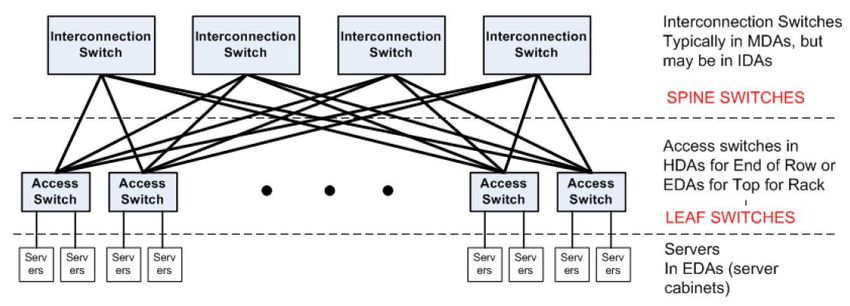
Lesson outline
Loops management in Ethernet networks: STP
I° Quadrimestre
Limitations of traditional datacenter network topologies
Leaf-spine topologies
Datacenter network topology with commodity switches: Fat-Tree
Paper: Mohammad Al-Fares, Alexander Loukissas, and Amin Vahdat.
A scalable, commodity data center network architecture.
SIGCOMM Computer Communications Review, vol. 38, issue 4, pp. 63-74, August 2008
Cloud and Datacenter Networking Course – Prof. Roberto Canonico – Università degli Studi di Napoli Federico II 2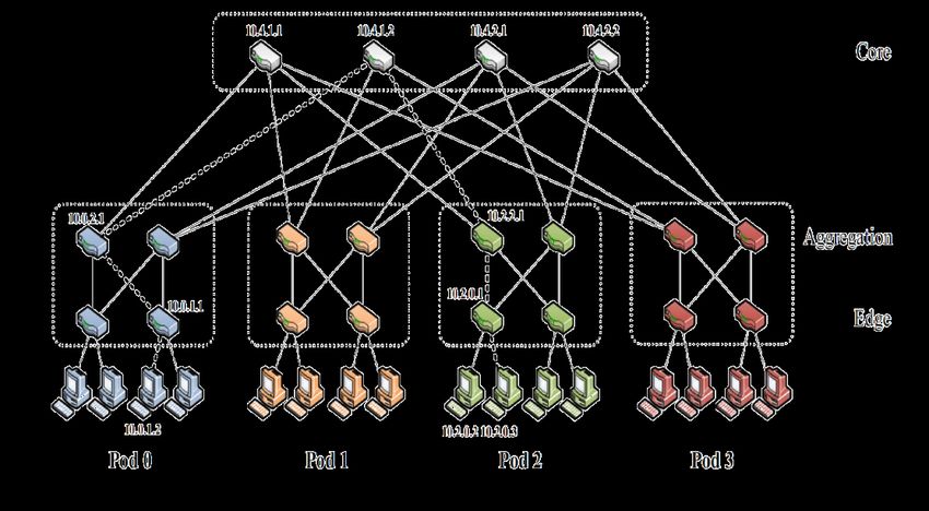
Traditional DC network architecture
In a datacenter computers are organized in racks to ease management and cabling and for
a more efficient utilization of space
Datacenter networks are typically organized in hierarchical structure
Server NICs (2/4 per server) connected to an access layer infrastructure
Access layer switches, in turn, are connected to an aggregation layer infrastructure
The whole datacenter is connected to the outside world (e.g. the Internet, or a private WAN)
through a core layer infrastructure operating at layer 3 (IP routing)
Cloud and Datacenter Networking Course – Prof. Roberto Canonico – Università degli Studi di Napoli Federico II 3
Requirements for a DC network architecture
Since building a datacenter is an expensive investment, its design needs to
satisfy a number of requirements that protect the investment in the long run
With regard to the networking infrastructure, it should be:
Cost-effective
Scalable
Reliable
Fault-tolerant
Energy efficient
Upgradable
Able to accommodate workloads varying over time
Able to isolate traffic from different customers/tenants
Easy to manage
Easy to protect against attacks / malicious traffic, …
…
Corso di Cloud e Datacenter Networking – Prof. Roberto Canonico 4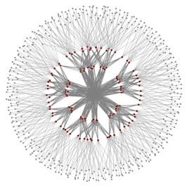
Datacenter networking and virtualization
In modern datacenters, servers’ computational resources may be efficiently utilized thanks
to a pervasive use of host virtualization technologies
KVM, Xen, Vmware, …
A single server may host tens of Virtual Machines (VM) each configured with one or more
virtual network interface cards (vNICs) with MAC and IP addresses of their own
Modern virtualization technologies allow to migrate a VM from one server to another with a
negligible downtime (live migration)
Condition for live migration transparency to running applications:
a migrating VM must keep its own IP address in the new position
If the datacenter network partitions the whole network infrastructure into clusters assigned
to different IP subnets, a VM cannot migrate outside of its original cluster
Migration is possible Migration is NOT possible
Server Server Server Server
VM VM VM VM
IP Subnet IP Subnet A IP Subnet B
Cloud and Datacenter Networking Course – Prof. Roberto Canonico – Università degli Studi di Napoli Federico II 5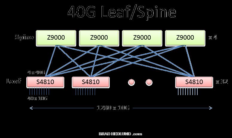
Datacenter traffic analysis
Observation: in large scale datacenters, traffic between hosts located in the DC (East-West
traffic or Machine-to-Machine traffic, m2m) exceeds traffic exchanged with the outside world
(North-South traffic)
Facebook: m2m traffic doubles in less than a year
Reasons: modern cloud applications a single client-generated interaction produces multiple
server-side queries and computation
Eg. Hints in a research textbox, customized ads, service mashups relying on multiple database
queries, etc.
Only a fraction of server-side produced data is returned to the client
An example observed in FB network (*):
a single HTTP request produced
88 cache lookups (648 KB),
35 database lookups (25.6 KB), and
392 remote procedure calls (257 KB) North-South traffic
Conclusion: the DC aggregation layer MUST NOT BE a bottleneck
for communications
(*) N. Farrington and A. Andreyev. Facebook’s data center network architecture.
In Proc. IEEE Optical Interconnects, May 2013
Arjun Roy, Hongyi Zeng, Jasmeet Bagga, George Porter, and Alex C. Snoeren.
Inside the Social Network's (Datacenter) Network.
SIGCOMM Computer Communications Review, 45, 4 (August 2015), pp. 123-137
East-West traffic
Cloud and Datacenter Networking Course – Prof. Roberto Canonico – Università degli Studi di Napoli Federico II 6Aggregation layer: simplest architecture
To achieve the maximum communications throughput within the datacenter, ideally the
aggregation layer could be made a single big non-blocking switch connecting all the access
layer switches
This is an impractical non-scalable solution: the switch crossbar should guarantee a throughput
too high to be achievable
This is the reason why DC network architectures are hierarchical
If the aggregation layer is not able to guarantee the required throughput,
applications performance is affected
Example: a cluster of 1280 servers organized in 32 racks with 40 servers each, with an
uplink from ToR switches formed by 4 x 10 Gb/s links and a single aggregation switch with
128 x 10 Gb/s ports (cost ≈ USD 700,000 in 2008)
If servers are equipped with 1 Gb/s NICs, total oversubscription is 1:1 → non-blocking network
Cloud and Datacenter Networking Course – Prof. Roberto Canonico – Università degli Studi di Napoli Federico II 7Multi-layer tree topologies
The picture shows a tree topology
Each switch connected to only one upper layer switch
Switches at the top of the hierarchy must have many ports and a very high aggregate bandwidth
Image by Konstantin S. Solnushkin (www.clusterdesign.org)
To avoid congestion probability, oversubscription must be kept as small as possible
A solution consists in connecting the various layers by means of multiple parallel links
To effectively use parallel links bandwidth → link aggregation solutions (eg. IEEE 802.3ad)
Cloud and Datacenter Networking Course – Prof. Roberto Canonico – Università degli Studi di Napoli Federico II 8Critics of tree-based topologies
Image by Konstantin S. Solnushkin (www.clusterdesign.org)
In practice, links between layers are subject to oversubscription N:1 (N>1)
For particular traffic matrices, congestion probability is not negligible
Poor elasticity: constraints in applications deployment
Servers that communicate more intensely must be located “more closely”
Greater latency with the increasing number of layers → Negative impact on TCP throughput
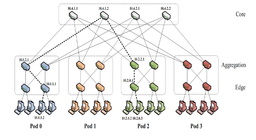
Cloud and Datacenter Networking Course – Prof. Roberto Canonico – Università degli Studi di Napoli Federico II 9Fat-tree: a scalable commodity DC network architecture
Topology derived from multistage Clos networks 3-layers fat-tree network k=4
Network of small cheap switches
3-layers hierarchy
k3/4 hosts grouped in
k pods with (k/2)2 hosts each
Peculiar characteristics:
The number of links (k/2) from each switch
to an upper layer switch equates the number
of links (k/2) towards lower-layer switches
→ No oversubscription (1:1)
k-port switches at all layers
Each edge switch connects k/2 hosts to k/2 aggregation switches
Each aggregation switch connects k/2 edge switches to k/2 core switches
(k/2) 2 core switches
Resulting property: each layer of the hierarchy has the same aggregate bandwidth
Mohammad Al-Fares, Alexander Loukissas, and Amin Vahdat.
A scalable, commodity data center network architecture.
SIGCOMM Computer Communications Review, 38, 4 (August 2008), pp. 63-74
Cloud and Datacenter Networking Course – Prof. Roberto Canonico – Università degli Studi di Napoli Federico II 10Datacenter network topology: fat-tree
k3/4 host raggruppati in
Rete fat-tree a tre livelli k=4
k pod da (k/2)2 host ciascuno
Ciascuno switch edge collega
k/2 server a k/2 switch aggregation
Ciascuno switch aggregation collega
k/2 switch edge a k/2 switch core
(5/4) k2 switch, di cui (k/2)2 switch core
La maggiore capacità dello strato core
si ottiene aggregando un elevato numero di link
k # host # switch core # switch
(k3/4) (k/2)2 (5/4) k2
4 16 4 20
12 432 36 180
16 1.024 64 320
24 3.456 144 720
32 8.192 256 1.280
48 27.648 576 2.880 3-level fat-tree
432 servers, 180 switches, k=12
96 221.184 2.304 11.520
Cloud and Datacenter Networking Course – Prof. Roberto Canonico – Università degli Studi di Napoli Federico II 11Fat-tree (continues)
Fat-tree network: redundancy
3-layers fat-tree network k=4
k different paths exist between any pair of hosts
Only one path exists between a given core switch
1 2 3 4
and any possible host
Question:
how is it possible to exploit the alternate paths ?
The network topology in the picture has:
16 access links (server-switch)
16 edge-aggregation link
16 aggregation-core links
No bottlenecks in the upper layers
A limited amount of oversubscription
may be introduced
(for instance, by using only 2 core switches)
Cloud and Datacenter Networking Course – Prof. Roberto Canonico – Università degli Studi di Napoli Federico II 12DC network architectures evolution
The approach of creating an aggregation layer formed by a few “big” switches with a huge
number of ports is not scalable
If oversubscription becomes too high, congestions may occur
Evolution: from tree-like topologies to multi-rooted topologies with multiple alternate paths
between end-system, where each switch is connected
to another upper-layer switch through multiple parallel uplinks
to multiple upper-layer switches
In such a way:
1. traffic may be split across multiple uplinks (i.e. oversubscription is kept as small as possible)
2. the whole system is more robust to switch/link failures thanks to the existence of multiple paths
…
Cloud and Datacenter Networking Course – Prof. Roberto Canonico – Università degli Studi di Napoli Federico II 13Multi-rooted Leaf-Spine topologies
Derived from Clos networks (folded Clos)
Two levels hierarchy, each leaf switch is connected to all spine switches
Advantage: elasticity
If the number of racks increases, the number of leaf switches increases
If network capacity is to be increased, the number of spine switches is to be increased
Cloud and Datacenter Networking Course – Prof. Roberto Canonico – Università degli Studi di Napoli Federico II 14A spine switch (2017)
Cisco Nexus 9364C
64 ports at 100 Gb/s → 6.4 Tb/s
2U size
Corso di Cloud e Datacenter Networking – Prof. Roberto Canonico 15A Leaf-Spine network with 40GbE links
https://s3.amazonaws.com/bradhedlund2/2012/40G-10G-leaf-spine/clos-40G.png
Cloud and Datacenter Networking Course – Prof. Roberto Canonico – Università degli Studi di Napoli Federico II 16Leaf-spine network with Port Extenders Cloud and Datacenter Networking Course – Prof. Roberto Canonico – Università degli Studi di Napoli Federico II 17
Google DC architecture in 2004
ToR switches connected by 1 Gb/s links to an upper aggregation layer made of 4 routers, in
turn connected to form a ring by means of couples of 10 Gb/s links
Each rack included 40 servers, equipped with 1 Gb/s NICs
A whole cluster included 512 ∙ 40 ≈ 20000 servers
Aggregate bandwidth of a cluster: 4 ∙ 512 ∙ 1 Gb/s = 2 Tb/s
Each rack could produce up to 40 Gb/s of aggregate traffic but racks were connected to
the upper layer router with a link capacity of 4 ∙ 1 Gb/s = 4 Gb/s
Congestions were possible if all the servers of a rack needed to communicate with the rest of DC
Traffic needed to be kept as local as possible within a rack
Arjun Singh, Joon Ong, Amit Agarwal, Glen Anderson, Ashby Armistead, Roy Bannon, Seb Boving, Gaurav Desai, Bob Felderman, Paulie Germano,
Anand Kanagala, Jeff Provost, Jason Simmons, Eiichi Tanda, Jim Wanderer, Urs Hölzle, Stephen Stuart, and Amin Vahdat.
Jupiter Rising: A Decade of Clos Topologies and Centralized Control in Google's Datacenter Network.
SIGCOMM Computer Communications Review, 45, 4 (August 2015), pp. 183-197
Cloud and Datacenter Networking Course – Prof. Roberto Canonico – Università degli Studi di Napoli Federico II 18Facebook DC architecture in 2013
Servers connected by 10 Gb/s links to a ToR switch(RSW) in each rack
RSW switches connected by 4 x 10 Gb/s uplinks to an aggregation layer formed by
4 cluster switches (CSW) connected to form a ring
Oversubscription: 40 servers ∙ 10 Gb/s : 4 uplinks ∙ 10 Gb/s = 10 : 1
A single ring of 4 CSWs identifies a cluster (e.g. including 16 racks)
The 4 CSW switches are connected in a ring topology by means of 8 x 10 Gb/s links
CSW switches connected by 4 x 10 Gb/s uplinks to a core layer formed by
4 Fat Cat (FC) switches connected to form a ring by means of 16 x 10 Gb/s links
Oversubscription: 16 rack ∙ 10 Gb/s : 4 uplink ∙ 10 Gb/s = 4 : 1
N. Farrington and A. Andreyev. Facebook’s data center network architecture. In Proc. IEEE Optical Interconnects, May 2013
Cloud and Datacenter Networking Course – Prof. Roberto Canonico – Università degli Studi di Napoli Federico II 19You can also read