Cisco IC3000 Industrial Compute Gateway Deployment Guide
←
→
Page content transcription
If your browser does not render page correctly, please read the page content below
Cisco IC3000 Industrial Compute Gateway Deployment Guide
First Published: 2021-02-28
Last Modified: 2021-02-16

Americas Headquarters
Cisco Systems, Inc.
170 West Tasman Drive
San Jose, CA 95134-1706
USA
http://www.cisco.com
Tel: 408 526-4000
     800 553-NETS (6387)
Fax: 408 527-0883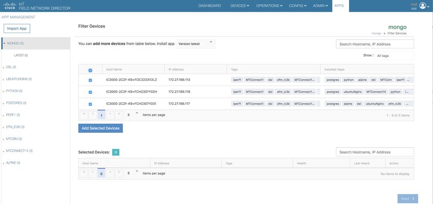
THE SPECIFICATIONS AND INFORMATION REGARDING THE PRODUCTS IN THIS MANUAL ARE SUBJECT TO CHANGE WITHOUT NOTICE. ALL STATEMENTS,
INFORMATION, AND RECOMMENDATIONS IN THIS MANUAL ARE BELIEVED TO BE ACCURATE BUT ARE PRESENTED WITHOUT WARRANTY OF ANY KIND,
EXPRESS OR IMPLIED. USERS MUST TAKE FULL RESPONSIBILITY FOR THEIR APPLICATION OF ANY PRODUCTS.

THE SOFTWARE LICENSE AND LIMITED WARRANTY FOR THE ACCOMPANYING PRODUCT ARE SET FORTH IN THE INFORMATION PACKET THAT SHIPPED WITH
THE PRODUCT AND ARE INCORPORATED HEREIN BY THIS REFERENCE. IF YOU ARE UNABLE TO LOCATE THE SOFTWARE LICENSE OR LIMITED WARRANTY,
CONTACT YOUR CISCO REPRESENTATIVE FOR A COPY.

The Cisco implementation of TCP header compression is an adaptation of a program developed by the University of California, Berkeley (UCB) as part of UCB's public domain version of
the UNIX operating system. All rights reserved. Copyright © 1981, Regents of the University of California.

NOTWITHSTANDING ANY OTHER WARRANTY HEREIN, ALL DOCUMENT FILES AND SOFTWARE OF THESE SUPPLIERS ARE PROVIDED “AS IS" WITH ALL FAULTS.
CISCO AND THE ABOVE-NAMED SUPPLIERS DISCLAIM ALL WARRANTIES, EXPRESSED OR IMPLIED, INCLUDING, WITHOUT LIMITATION, THOSE OF
MERCHANTABILITY, FITNESS FOR A PARTICULAR PURPOSE AND NONINFRINGEMENT OR ARISING FROM A COURSE OF DEALING, USAGE, OR TRADE PRACTICE.

IN NO EVENT SHALL CISCO OR ITS SUPPLIERS BE LIABLE FOR ANY INDIRECT, SPECIAL, CONSEQUENTIAL, OR INCIDENTAL DAMAGES, INCLUDING, WITHOUT
LIMITATION, LOST PROFITS OR LOSS OR DAMAGE TO DATA ARISING OUT OF THE USE OR INABILITY TO USE THIS MANUAL, EVEN IF CISCO OR ITS SUPPLIERS
HAVE BEEN ADVISED OF THE POSSIBILITY OF SUCH DAMAGES.

Any Internet Protocol (IP) addresses and phone numbers used in this document are not intended to be actual addresses and phone numbers. Any examples, command display output, network
topology diagrams, and other figures included in the document are shown for illustrative purposes only. Any use of actual IP addresses or phone numbers in illustrative content is unintentional
and coincidental.

All printed copies and duplicate soft copies of this document are considered uncontrolled. See the current online version for the latest version.

Cisco has more than 200 offices worldwide. Addresses and phone numbers are listed on the Cisco website at www.cisco.com/go/offices.

Cisco and the Cisco logo are trademarks or registered trademarks of Cisco and/or its affiliates in the U.S. and other countries. To view a list of Cisco trademarks, go to this URL:
https://www.cisco.com/c/en/us/about/legal/trademarks.html. Third-party trademarks mentioned are the property of their respective owners. The use of the word partner does not imply a
partnership relationship between Cisco and any other company. (1721R)
© 2018–2021   Cisco Systems, Inc. All rights reserved.
CHAPTER                 1
              Unboxing, Installing, and Connecting the IC3000
              This section contains the following topics:
                 • Introduction, on page 1
                 • Related Documentation, on page 4

Introduction
              The IC3000 Industrial Compute Gateway (IC3000) is an edge computing platform which extends the cloud
              computing paradigm to the edge of the network. Instead of hosting applications in a remote data center,
              applications can now be hosted on the edge itself. Imagine, if we can host specific applications in the field
              close to the sensors, meters or the things. whatever may be the IOT use case, IC3000 serves the purpose by
              allowing us to deploy applications that need more cores and memory.

       Note   The documentation set for this product strives to use bias-free language. For purposes of this documentation
              set, bias-free is defined as language that does not imply discrimination based on age, disability, gender, racial
              identity, ethnic identity, sexual orientation, socioeconomic status, and intersectionality. Exceptions may be
              present in the documentation due to language that is hardcoded in the user interfaces of the product software,
              language used based on RFP documentation, or language that is used by a referenced third-party product.

              The Cisco IC3000 Industrial Compute Gateway is fully supported by Cisco IoT Field Network Director for
              zero-touch deployment, lifecycle management, application management, monitoring, and troubleshooting
              securely at scale from a single pane of glass.
              The IC3000 is a mid-range, low-power, fanless, edge server ruggedized for Industrial Applications. It is
              powered by a 4 core 1.2GHz Intel Rangeley CPU with 8 GB of 1333MHz DDR3 memory, and a 100GB
              mSATA drive (internal). For connectivity it supports 2x1GbE SFP and 2x10/100/1000Base-T with a
              management port.
              This next section describes the phases you will need to follow for a successful installation.

       Note   Examples shown in this document use IP addresses that are from a lab environment and should not be used
              on a typical customer installation.

                                                            Cisco IC3000 Industrial Compute Gateway Deployment Guide
                                                                                                                        1
Unboxing, Installing, and Connecting the IC3000
   Unboxing, Installing and Connecting to the IC3000 Device

Unboxing, Installing and Connecting to the IC3000 Device
Unboxing the IC3000
                         Complete details for the hardware installation of the product are covered in the Cisco IC3000 Industrial
                         Compute Gateway Hardware Installation Guide . The following steps are a high level overview.

Installing the IC3000
                         1. Review the general description of the unit in the Product Overview section of the hardware installation
                            guide.
                         2. Check the Equipment, Tools, and Connections section of the hardware installation guide to ensure you
                            have everything you need for the installation.
                         3. Review the procedures for Mounting, Grounding, Connecting to DC Power and Connecting to the IC3000
                            in the hardware installation guide.
                         4. If you are installing the device in a Hazloc location, follow the printed instructions that came inside the
                            box with the device.
                         5. Power on the device.

Connecting the IC3000 to a PC

                         Procedure

            Step 1       Connect a PC to the device. If your PC warns you that you do not have the proper drivers to communicate
                         with the device, you can obtain them from your computers manufacturer or go to:
                         https://software.cisco.com/download/home/282774227/type/282855122/release/3.1

            Step 2       Determine how your computer mapped the new COM port that was created when you installed the USB-to-serial
                         port driver. You need this information to appropriately configure your serial communications program in the
                         next step.
            Step 3       Start your serial communications program and connect to the router. The console port settings to use for the
                         serial connection are:
                             • 9600 baud
                             • 8 data bits
                             • 1 stop bit
                             • no parity
                             • no flow control
                         If the device is properly connected and powered up, you should see the ic3k> prompt.

            Step 4       Verify that your computer is properly connected to the device by checking the LEDs on the unit as described
                         in the Hardware Installation Guide.

                         What to do next
                         There is a new banner during boot starting with release 1.3.1, informing the user to use Local Manager or
                         FND for configuring the networking and device. For example:

                     Cisco IC3000 Industrial Compute Gateway Deployment Guide
        2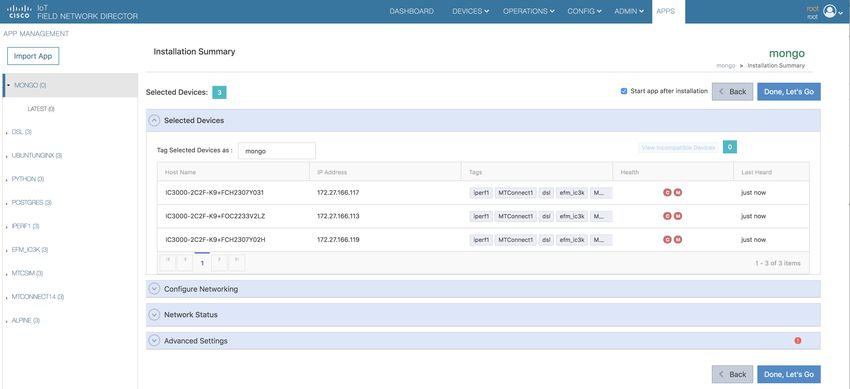
Unboxing, Installing, and Connecting the IC3000
                                                                                                                       IC3000 Show Commands

                           Press RETURN to get started

                           *******************************************************************************

                                                   *
                           *        CLI is for viewing configuration, settings and device information                              *
                           *
                                                             *
                           *     Use Field Network Detector/Local Manager for configuring IC3000         *
                           ******************************************************************************

IC3000 Show Commands
                           The following show commands are supported on the device via the console. Unlike other Cisco routers, the
                           IC3000 only supports one user mode, which is user EXEC mode. The device prompt shows as ic3k>.
                           The CLI and prompt is a CLISH wrapper built on top of Linux OS for administrator usage.

Table 1: show commands

Show Command                            Description

show version                            shows the version information

show dns                                shows the domain name service information

show ida status                         shows the device management tool connection information

show ntp                                shows the network time protocol information

show techsupport                        shows the technical support logs

show iox                                shows the IOx application hosting information

show iox summary                        shows the application hosting summary

show iox detail                         shows the application hosting details

show operating-mode                     shows operating mode information

show ntp manual config                  shows the ntp configuration pushed from FND or LM

show ntp association                    shows the ntp association information

show ntp status                         shows whether the device has been synced with ntp server

show ntp mode                           shows whether ntp config mode is in auto or manual mode

show dns manual config                  shows the dns configuration pushed from FND or LM

show dns mode                           shows whether dns config mode is in auto or manual mode

show clock                              shows the time on the device

help standalone-mode                    shows instructions for configuring standalone-mode

help managed-mode                       shows instructions for configuring managed-mode

                                                                        Cisco IC3000 Industrial Compute Gateway Deployment Guide
                                                                                                                                         3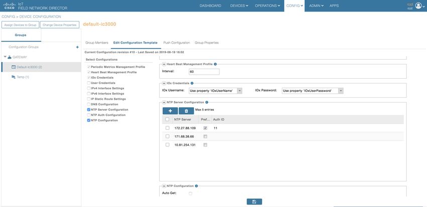
Unboxing, Installing, and Connecting the IC3000
   Related Documentation

Show Command                        Description

show sfp information port3/port4 Shows the Fiber/Copper SFP details.

show golden image                   Shows the golden image and golden application image (If the device is shipped with application).

show tech support usb2/sdcard       Show tech support no longer prints on console. Support has been added for downloading logs to
                                    usb2.

                       There are examples of command output to illustrate the show commands located in Additional Administration
                       > Troubleshooting. Your device may show different results depending on your configuration.

Related Documentation
                       All of the IC3000 documentation is found here:
                       https://www.cisco.com/c/en/us/support/routers/3000-series-industrial-compute-gateways/tsd-products-support-series-home.html
                       For information about FND, go to the following:
                       https://www.cisco.com/c/en/us/support/cloud-systems-management/iot-field-network-director/tsd-products-support-series-home.html
                       Cisco Fog Director Reference Guide:
                       http://www.cisco.com/c/en/us/support/cloud-systems-management/fog-director/products-technical-reference-list.html
                       Cisco IOx Local Manager User Guide
                       https://www.cisco.com/c/en/us/support/cloud-systems-management/iox/products-technical-reference-list.html
                       For additional information about Cisco IOx, go to the following:
                       DevNet documentation on IOx. Provides an overview as well as details by scrolling down the left hand side:
                       https://developer.cisco.com/site/devnet/support/
                       Cisco IOx:
                       https://www.cisco.com/c/en/us/support/cloud-systems-management/iox/tsd-products-support-series-home.html

                    Cisco IC3000 Industrial Compute Gateway Deployment Guide
        4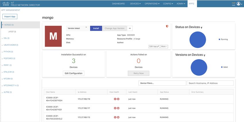
CHAPTER                 2
              Managing the IC3000 with Field Network Director
              (FND)
              The following steps show how to install and manage your device with FND.
                 • Step 1: Installing FND, on page 5
                 • Step 2: DHCP Options, on page 6
                 • Step 3: Understanding the Device Configuration Template, on page 7
                 • Step 4: NTP Configuration, on page 8
                 • Step 5: DNS Configuration, on page 9
                 • Step 6: Adding the IC3000 Gateway(s) to FND, on page 10
                 • Step 7: IC3000 Registration, on page 12
                 • Step 8: Uploading the Firmware to FND, on page 12
                 • Step 9: Upgrading Firmware with FND, on page 13
                 • Step 10: Deploying IOx Applications via FND, on page 13

Step 1: Installing FND
              If this is your first time setting up the FND OVA infrastructure, go to Appendix for complete information.
              Download the IoT Field Network Director software from this location:
              https://software.cisco.com/download/home/286287993/type
              Visit FND URL https:/// and change the password for root user. Default
              username/password is root/root123

       Note   Change the ADMIN > SYSTEM MANAGEMENT > PROVISIONING SETTINGS > IOT FND URL
              with the FND IP address as shown below. Otherwise, registration may fail.

                                                        Cisco IC3000 Industrial Compute Gateway Deployment Guide
                                                                                                                   5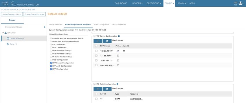
Managing the IC3000 with Field Network Director (FND)
  Step 2: DHCP Options

                         Figure 1: Provisioning Settings

Step 2: DHCP Options
                         If the IC3000 gateway gets an IP address from the DHCP server, Option 43 is used to advertise the FND IP
                         address and Option 42 is used to advertise the NTP server IP address via DHCP.
                         The management interface sends a DHCP option 60, also known as vendor-class-identifier, in its request. The
                         device identification is sent as the string cisco-ic3000. Upon receiving the vendor-class-identifier, the DHCP
                         server can take actions as required.

Example of DHCP Option 42 and 43
                         Configure the following on an IR8x9:

                         ip dhcp pool ic3000_pool2
                         network 172.27.88.0 255.255.255.128
                         dns-server 173.36.131.10
                         option 43 ascii 5A;K4;B2;I172.27.88.63;J9125
                         option 42 ip 171.70.168.183
                         default-router 172.27.88.1
                         lease 0 0 2

                         Please make note of Option 43 usage:

                             • If you have a DHCP server, use the “same” PNP discovery option string that we use for regular IOS
                               routers Option 43 ascii “5A;K4;B2;I172.27.88.63;J9125" (IGMA will use port 9121 as default. IoT FND
                               IP is 172.27.88.63)
                             • If you wish to use a different port provide the following configuration:
                         option 43 ascii “5A;K4;B2;I192.168.10.6;J9125;W9128"
                         On a regular Linux server running DHCP, use the following instructions:

                         cat /etc/dhcp/dhcpd.conf
                         subnet 10.10.100.0 netmask 255.255.255.0 {

                         option routers 10.10.100.1;
                         range 10.10.10.100 10.10.10.199;
                         option domain-name-servers 10.10.100.1;
                         option domain-name "test1.dom";
                         option vendor-encapsulated-options "5A;K4;B2;I10.48.43.227;J9125";
                         }

                         In the above example for option 43, the following describes the options:

                   Cisco IC3000 Industrial Compute Gateway Deployment Guide
       6
Managing the IC3000 with Field Network Director (FND)
                                                                                                                           Option 42 Usage

                             • 5A;K4;B2;I172.27.88.63;J9125
                                   • 5 – DHCP type code 5
                                   • A – Active feature operation code
                                   • ; - Delimiter
                                   • K4 – HTTP transport protocol
                                   • B2 – PnP server /FND IP address type is IPv4
                                   • J9125 - port number

Option 42 Usage
                         The system time may not be synchronized when receiving the device from the factory. It is important to
                         provide ntp server information to get the device clock to current time. This will avoid any issues when
                         establishing a connection to FND and make sure the timestamp on data packets from apps are up to date.
                         On a regular Linux server running DHCP, use the following instructions:

                         cat /etc/ntp.conf
                         subnet 10.10.100.0 netmask 255.255.255.0 {
                         max-lease-time 604800;
                         default-lease-time 86400;
                         option ntp-servers 10.10.100.112;
                         }

Step 3: Understanding the Device Configuration Template
                         There is a default template within the FND for IC3000. It is located under CONFIG >Device Configuration
                         tab > default-IC3000 > Edit Configuration template. See Step 6: Adding the IC3000 Gateway(s) to FND,
                         on page 10.
                         Edit the interface configuration or add interface settings as required by your use case. Once edited, use the
                         Push Configuration tab to push the new configuration to the active or registered devices.

                Note     It is important to make sure the map is correctly configured. If valid entries do not exist, you will get an error
                         message like the on shown in the following image. This error does not impact the operation of the device,
                         you can still continue.

                                                                     Cisco IC3000 Industrial Compute Gateway Deployment Guide
                                                                                                                                       7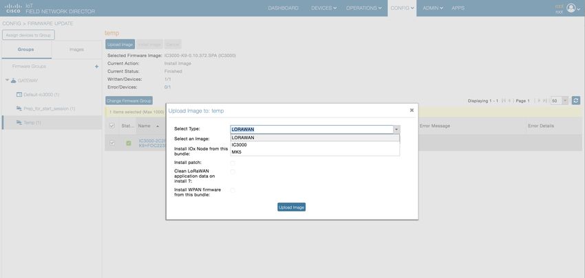
Managing the IC3000 with Field Network Director (FND)
  Step 4: NTP Configuration

                        Figure 2: Map Error

Step 4: NTP Configuration
                        To push the NTP configuration via FND, perform the following:

                        Procedure

           Step 1       Go to FND GUI > Config > Device Configuration > Edit Configuration Template.
           Step 2       Select both the NTP Server Configuration and the NTP Configuration checkbox.
                        a) Optional: Select the NTP Auth Configuration checkbox if the NTP server has been configured with
                           authentication. Add the Key ID and corresponding SHA1 key as the password. Refer to Figure 3: Add
                           NTP Authentication, on page 8. Note: NTP Authentication is only offered for NTP servers that support
                           SHA1.
                        b) Optional: Select the Auto Get checkbox under NTP Configuration to delete the NTP configuration that
                           has been manually pushed onto the device from FND
                        Figure 3: Add NTP Authentication

           Step 3       Add the NTP server entry. Click the + symbol under NTP Server Configuration. Refer to Figure 4: Add NTP
                        Configuration, on page 9.
                        a) To prioritize a certain NTP server for clock synchronization, click the Preferred checkbox

                    Cisco IC3000 Industrial Compute Gateway Deployment Guide
       8
Managing the IC3000 with Field Network Director (FND)
Step 5: DNS Configuration
b) If NTP authentication is to be configured, add the Key ID set in the NTP Auth Configuration as the Auth
ID.
Figure 4: Add NTP Configuration
Step 4 Push NTP configuration by going to Push Configuration > Select Operation Scroll down > Push
GATEWAY Configuration > Start. Refer to Figure 5: Push NTP Configuration, on page 9.
Figure 5: Push NTP Configuration
Step 5 The NTP Configuration is now complete.
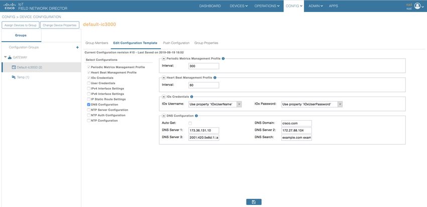
Step 5: DNS Configuration
To push DNS configuration via FND perform the following steps, referring to Figure 6: Add DNS
Configuration, on page 10 for guidance.
Procedure
Step 1 Go to FND GUI > Config > Device Configuration > Edit Configuration Template.
Step 2 Select the DNS configuration checkbox.
Step 3 Add DNS search, domain, or server entries.
Cisco IC3000 Industrial Compute Gateway Deployment Guide
9Managing the IC3000 with Field Network Director (FND)
Step 6: Adding the IC3000 Gateway(s) to FND
a) Optional: Select the Auto Get checkbox within the DNS Configuration tab to delete the DNS configuration
that has been manually pushed onto the device from FND.
Step 4 Push the DNS configuration by navigating to Push Configuration > Select Operation Scroll down > Push
GATEWAY Configuration > Start.
Figure 6: Add DNS Configuration
Step 6: Adding the IC3000 Gateway(s) to FND
Follow these steps to add your device to FND.
Procedure
Step 1 Prepare a spreadsheet with the list of devices to add. This must be completed before adding devices to avoid
additional steps. The default template is in .csv format, and can be downloaded from the FND - import
Inventory -> Add device tab.
Your spreadsheet will need the fields as shown in the following example:
Example:
eid deviceType lat lng IOxUserName
IOxUserPassword
IC3000-2C2F-K9+FOC2227Y2ZC IC3000 37.414639 -121.936836 sampleadmin
IC3000password
Note The eid is a combination of the PlatformID+HardwareID. The platform id for the IC3000 is always
IC3000-2C2F-K9 and the HardwareID or Serial number is unique for each platform. The serial
number can be read from the label on the box, or if you have access to the console of the device run
the show version command and the hardware id /serial number will be displayed.
Cisco IC3000 Industrial Compute Gateway Deployment Guide
10Managing the IC3000 with Field Network Director (FND)
Step 6: Adding the IC3000 Gateway(s) to FND
Note The latitude (lat) and Longitude (lng) entries in the spreadsheet will need to represent actual values,
complete with decimal notation. For latitude, a positive number represents North and a negative
number represents South. For longitude, a positive number represents East and a negative number
represents West. Failure to specify an actual value will result in an error being displayed from
Google Maps.
Note The following password rules for the IOxUserPassword must be adhered to:
Minimum length = 6
Must not be based upon a dictionary word
Must not be a combination of dictionary words
Must not be composed of common string patterns like “qwerty”, “asdfgh” etc...
Must not be a combination of common string patterns and dictionary words
Currently not supporting Unicode
To download a sample spreadsheet go to FND -> Inventory -> Add devices. Then click IC3000.
Step 2 Get the Serial number and Model number and use system as the ioxusername and admin as the password. The
serial number is located on the device label and is something like "FOC2227Y304". The serial number can
also be found through the show version command output:
Example:
ic3k>show version
Version: 1.2.1
Platform ID: IC3000-2C2F-K9
Hardware ID: FOC2227Y304
ic3k>
Step 3 Click DEVICES > FIELD DEVICES > Inventory > Add Devices. Browse to the location of your excel
spreadsheet and click Add. See Figure 7: Add Devices, on page 11.
Figure 7: Add Devices
Note The IC3000 belongs under the gateway category when adding devices.
Cisco IC3000 Industrial Compute Gateway Deployment Guide
11Managing the IC3000 with Field Network Director (FND)
Step 7: IC3000 Registration
Step 7: IC3000 Registration
After you add devices to the IoT FND (FND) Network Management application, wait for a few minutes for
the IC3000 devices to learn the option 43 settings from the DHCP server, and then register with FND. Once
the IC3000 gets an ip address from DHCP server, the option 43 issues an FND IP address for the device to
register to FND.
Note Make sure the DHCP server settings are set properly with FND IP in option 43 string.
Once the device is registered you should see the registration events listed for each IC3000 unit as shown in
the example on Figure 8: Device Registration, on page 12.
Figure 8: Device Registration
The refresh metric should work and should be able to refresh the device related details.
Step 8: Uploading the Firmware to FND
In order to upgrade the firmware of the IC3000, you must download the required firmware from Cisco.com
to upload the firmware to FND.
Select CONFIG > Firmware Update > Images. A list of the IC3000 images is presented. Click + - and
upload the required image. See Figure 9: Firmware Upload, on page 13.
Cisco IC3000 Industrial Compute Gateway Deployment Guide
12Managing the IC3000 with Field Network Director (FND)
Step 9: Upgrading Firmware with FND
Figure 9: Firmware Upload
Step 9: Upgrading Firmware with FND
Once Step 5: DNS Configuration, on page 9 is complete, you may now upgrade the firmware against the
registered Units that require the update.
Select CONFIG > Firmware update > Select the device group > Upload Image
Once the Image upload is complete, select the Install Image tab and proceed with upgrading the firmware.
Figure 10: Firmware Update
Step 10: Deploying IOx Applications via FND
To deploy an IOx application perform the following:
Procedure
Step 1 From the Main page select APP > Import Apps and select the required application to install.
Cisco IC3000 Industrial Compute Gateway Deployment Guide
13Managing the IC3000 with Field Network Director (FND)
Step 10: Deploying IOx Applications via FND
Figure 11: Application Upload
Once imported, you will find the list of applications imported in the left column.
a) To upload an application from your local machine that has been packaged using IOx client, use the IOx
Package option as shown in Figure 12: Import New App (IOx Package Option), on page 14
Figure 12: Import New App (IOx Package Option)
b) To upload an OVA VM application use the OVA option as shown in Figure 13: Import New App (OVA
Option), on page 15.
Cisco IC3000 Industrial Compute Gateway Deployment Guide
14Managing the IC3000 with Field Network Director (FND)
Step 10: Deploying IOx Applications via FND
Figure 13: Import New App (OVA Option)
c) To upload a native docker app from the docker hub/registry or from your local machine use the Docker
option as shown in Figure 14: Import New App (Docker Option), on page 15.
Note To upload a native docker application using the docker hub option just pass the docker image name
exactly as shown from the docker hub.
Figure 14: Import New App (Docker Option)
Step 2 Select the application that needs to be installed and click Install.
Note You can now import multiple versions of the same application (IoT FND 4.5 and greater).
Cisco IC3000 Industrial Compute Gateway Deployment Guide
15Managing the IC3000 with Field Network Director (FND)
Step 10: Deploying IOx Applications via FND
Figure 15: Application Install
Step 3 Select the Devices > Add Selected Devices. With your device present, click Next
Figure 16: Add Devices
Select the appropriate actions and tabs and provide details as required. See Figure 17: Selected Device Action
Tabs, on page 16
Figure 17: Selected Device Action Tabs
Step 4 Then click Done, Let’s Go. The Installation progress window appears. See Figure 18: Installation Progress,
on page 17.
Cisco IC3000 Industrial Compute Gateway Deployment Guide
16Managing the IC3000 with Field Network Director (FND)
Step 10: Deploying IOx Applications via FND
Figure 18: Installation Progress
If installation is successful, you should be able to see the installed count increasing. See Figure 19: Installation
Successful, on page 17.
Figure 19: Installation Successful
Cisco IC3000 Industrial Compute Gateway Deployment Guide
17Managing the IC3000 with Field Network Director (FND)
Step 10: Deploying IOx Applications via FND
Cisco IC3000 Industrial Compute Gateway Deployment Guide
18CHAPTER 3
Standalone Mode: Testing IOx Applications Via
Local Manager
This section contains the following topics:
• Understanding Standalone Mode, on page 19
• Understanding Managed Mode, on page 19
• Standalone Mode Connectivity, on page 19
• Upgrading the IC3000 Firmware with Local Manager, on page 21
Understanding Standalone Mode
Typically, when connected to the IC3000 through a laptop, you are in standalone mode. This mode is suitable
for developers, system integrators or engineers who want to test or build an application, which is specific to
their choice of use case, before deploying in large scale via FND. It is assumed that the IOX client utility can
be used to package the application as a container or Docker.
For additional information, refer to Remote Device Management, on page 34. To see an example, go to Use
Case Example: Installing a Prebuilt Application via Local Manager, on page 31.
Understanding Managed Mode
This mode is typically when the IC3000 has been deployed in field, and actively performing in the field hosting
apps that were prebuilt and designed to run. This mode must be managed by FND. The device management
ports learn the DHCP address and gradually registers with FND. Please refer to Step 7: IC3000 Registration,
on page 12.
Standalone Mode Connectivity
Consider the following points in order to connect to the IC3000 in standalone mode:
• Brand new devices (fresh from Cisco factory) have the capability of determining the mode autonomously
depending on the networking configurations.
• Standalone mode enables the Cisco IOx Local Manager interface which can be accessed via the browser
on the computer connected to the gateway.
Cisco IC3000 Industrial Compute Gateway Deployment Guide
19Standalone Mode: Testing IOx Applications Via Local Manager
Standalone Mode Connectivity
• Standalone mode is activated ONLY over the management Ethernet port of the device.
• Standalone mode CANNOT be turned ON via FND.
• An IC3000 deployed in managed mode can be re-configured to operate in standalone mode by pressing
the "Config-Reset" button on the device. Refer to reset button options in IC3000 Related , on page 45
for details.
Standalone mode operates only over a predetermined IPv4 link local address for the first time. To extend the
standalone mode to use a LAN/WAN address, please follow the steps in Remote Device Management, on
page 34. The Remote management feature is turned on by default from release 1.2.1 and greater, so that the
local manager access is available on all the time.
Steps to Connect to the Management Port:
The following graphic shows a laptop connected to the management interface via a standard Ethernet cable.
Figure 20: PC Connected to Management Interface
(Management Interface Configuration) (Laptop Configuration)
IP address 169.254.128.2Netmask 255.255.0.0 IP address 169.254.128.4Netmask 255.255.0.0
IDA maintains a service which monitors the management interface every 30 seconds. If IDA detects the IP
address is not available, IDA will assign the link local IP address of 169.254.128.2 to the management interface.
If the device is in managed mode, IDA will enable the device configuration page as well. Once the WebSocket
connection is established, IDA will disable the device configuration page.
Note This is new with release 1.3.1. This enhancement will only be effective when the management interface is
using a DHCP configuration.
Cisco IC3000 Industrial Compute Gateway Deployment Guide
20Standalone Mode: Testing IOx Applications Via Local Manager
Upgrading the IC3000 Firmware with Local Manager
Procedure
Step 1 Follow steps 1-4 of Installing the IC3000, on page 2.
Step 2 Connect the Management interface on the IC3000 and your laptop with a console cable.
Step 3 Do not power on the IC3000 yet.
Step 4 Assign the IP address of 169.254.128.4 with a netmask of 255.255.0.0 to the network interface on your
computer.
Note It is critical you assign this specific IPv4 link-local address.
Step 5 Now, power-on the IC3000.
Step 6 The device will be in discovery state for the first 30 seconds to learn its dhcp address. After 30 seconds the
device will assign an LLA address.
Step 7 The IC3000 will be ready to operate in standalone mode in 30 seconds (The delay of 30 seconds only occurs
the first time a device is booted up. All subsequent reloads will immediately take the device to standalone
mode without delay).
Step 8 Open a browser on your laptop and enter https://169.254.128.2:8443 as a URL. The Local Manager opens.
Enter admin/cisco123 as your username/password, and then update the default password.
Note admin/cisco123 is the default account credentials from release 1.2.1 release and greater.
Password Rules:
The following password rules must be adhered to:
• Minimum length = 6
• Must not be based upon a dictionary word
• Must not be a combination of dictionary words
• Must not be composed of common string patterns like “qwerty”, “asdfgh” etc...
• Must not be a combination of common string patterns and dictionary words
• Currently not supporting Unicode
Step 9 For devices running 1.2.1, use the default credentials (admin/cisco123) for logging in the first time. The user
is required to change the password when logging in the first time. The IC3000 devices running 1.1.1 and 1.0.1
may need to create or use developer credentials to login via local manager.
Upgrading the IC3000 Firmware with Local Manager
The following steps are used to upgrade the device firmware through the Local Manager GUI in Standalone
Mode.
Procedure
Step 1 Login to LM GUI using the LLA address
Step 2 Use the default or newly created password (default is admin/cisco123).
Cisco IC3000 Industrial Compute Gateway Deployment Guide
21Standalone Mode: Testing IOx Applications Via Local Manager
Upgrading the IC3000 Firmware with Local Manager
Step 3 Once you are logged into the GUI, click on the Device Config tab, then select the Software Upgrade. (See
Figure 21: Device Config Tab, on page 22).
Step 4 Select the image file and then click Upload & Install.
Step 5 If you receive any pop-up messages click OK.
Step 6 The image is pushed to the IC3000 and it is rebooted with the new firmware.
Figure 21: Device Config Tab
Cisco IC3000 Industrial Compute Gateway Deployment Guide
22CHAPTER 4
Connecting and Managing via Local Manager
(LM)
This section contains the following topics:
• About Local Manager, on page 23
• Accessing the IC3000 via Local Manager, on page 23
• Setting the Date and Time, on page 25
• Setting NTP Manually, on page 27
• Setting DNS Manually, on page 29
• Software Reboot Button, on page 30
• Use Case Example: Installing a Prebuilt Application via Local Manager, on page 31
• Additional Examples, on page 34
• Remote Device Management, on page 34
About Local Manager
Cisco IOx Local Manager provides a web-based user interface that you can use to manage, administer, monitor,
and troubleshoot applications on a device, and to perform a variety of related activities.
Accessing the IC3000 via Local Manager
Find the Management port address to access the IC3000 via a web browser. After connecting the IC3000 to
a laptop, gather the svcbr_0 address whether you are in managed mode, or standalone mode. Use the show
interfaces command to determine the IP address, or if you are managing the device via FND, get the device
IP address. Use the ioxusername and ioxpassword to login via Local Manager, or you can create users on the
IC3000 from the device configuration tab. Use the json commands to create users and passwords that Local
Manger can use.
ic3k>show interfaces
svcbr_0 Link encap:Ethernet HWaddr f8:b7:e2:b5:26:80
inet addr:172.27.127.174
Bcast:172.27.127.255 Mask:255.255.255.0
inet6 addr: fe80::fab7:e2ff:feb5:2680/64 Scope:Link
UP BROADCAST RUNNING MULTICAST MTU:1500 Metric:1
Cisco IC3000 Industrial Compute Gateway Deployment Guide
23Connecting and Managing via Local Manager (LM)
Accessing the IC3000 via Local Manager
RX packets:396 errors:0 dropped:0 overruns:0 frame:0
TX packets:25 errors:0 dropped:0 overruns:0 carrier:0
collisions:0 txqueuelen:1000
RX bytes:29614 (28.9 KiB) TX bytes:3373 (3.2 KiB)
Note If the IC3000 is in standalone mode, you will be using an IPv4 LLA address of 169.254.128.x. The rest of
the following work flow is the same.
Procedure
Step 1 Open a web browser and enter https://169.254.128.2:8443 in the address bar.
Step 2 Login by using the default credentials admin/cisco123 for the first time if you are running release 1.2.1. For
older devices running 1.1.1 or 1.0.1, use developer/. This is the password that was created
by the developer set-password or developer change-password command. You should have various tabs
that Local Manager supports, since you are accessing the device via Local Manager. You should be familiar
with the standalone mode options like Device Config tab.
If a security exception message appears in your browser, confirm the exception to continue to the Cisco IOx
Local Manager Login screen.
If you see the message "For best results use a supported browser" near the top of this screen, your browser
may have compatibility issues with this version of Cisco IOx Local Manager. In this case, we recommend
that you load a compatible browser. Hover your mouse pointer over the down-arrow next to this message to
see a list of compatible browsers as shown in Figure 22: Supported Browsers, on page 24.
Figure 22: Supported Browsers
Cisco IC3000 Industrial Compute Gateway Deployment Guide
24Connecting and Managing via Local Manager (LM)
Setting the Date and Time
Step 3 Click Log In. The Local Manager Applications Tab appears. See Figure 23: Local Manager Applications
Tab, on page 25.
What to do next
Figure 23: Local Manager Applications Tab
Setting the Date and Time
The time feature in Local Manager provides the user with the ability to change the system time, date and time
zone on an IC3000. Although this feature is available, it is still recommended to provide access to an NTP
server to avoid any issues.
Release 1.3.1 provides enhanced capabilities. The user can now select the time source between manual date
and time or NTP. When using NTP, the user can provide information about NTP servers manually, or get that
information from a DHCP Server.
The following are options that the user can select from the Device Configuration page of the User Interface
(UI):
• Manual Date and Time (User provides the information)
• Network Time Protocol (NTP)
• Auto (DHCP Server provides the information)
• Manual (User provides the information)
Note Either Manual or NTP date and time options can be selected.
Some of the feature caveats are:
• Time Zone can be individually selected by the customer regardless of the time source.
• Up to 5 NTP servers and 1 Preferred NTP server
• Polling interval includes max and min poll
• For NTP Authentication, the user provides the id, type, and value of the keys
• For NTP, either hostname or IP address can be used.
From the Local Manager GUI, click on the Device Config Tab. The following shows the Time Source section
highlighted.
Cisco IC3000 Industrial Compute Gateway Deployment Guide
25Connecting and Managing via Local Manager (LM)
Setting the Date and Time
Figure 24: Local Manager Time Source
From this section, you can click on Manuel or NTP as your time source. Choosing NTP defaults to Auto.
Click Configure NTP and the settings are updated.
To configure your Date and Time manually, select the Manual button. The Time Source window appears as
the following:
Figure 25: Manual Date and Time
Fill in the date and time you wish and then click Configure Time.
Cisco IC3000 Industrial Compute Gateway Deployment Guide
26Connecting and Managing via Local Manager (LM)
Setting NTP Manually
To configure NTP manually, move on to the next section.
Setting NTP Manually
The NTP feature in Local Manager provides the user with the ability to set Network Time Protocol (NTP)
manually on an IC3000.
Procedure
Step 1 From the Local Manager GUI, click on the Device Config Tab.
Step 2 Under the Time Source section, click on NTP. Refer to the following:
Step 3 Beside the Mode, select the pulldown and click Manual. Refer to the following graphic.
Cisco IC3000 Industrial Compute Gateway Deployment Guide
27Connecting and Managing via Local Manager (LM)
Setting NTP Manually
Figure 26: NTP Manual Configuration
Step 4 Fill out the NTP entries, then click the plus sign (+)
Note Optional: Add an NTP Key entry if the NTP server has been configured with authentication. Add
the Key ID and corresponding SHA1 key as the password.
Note Note: Authentication is only offered for NTP servers that support SHA1.
Step 5 Click Configure NTP.
What to do next
Note To check if the device has synchronized to the NTP server, run the command show ntp status on the IC3000.
If the NTP server is reachable, it will show a message stating the clock is synchronized:
Cisco IC3000 Industrial Compute Gateway Deployment Guide
28Connecting and Managing via Local Manager (LM)
Setting DNS Manually
IC3000> show ntp status
Clock is synchronized, stratum 3, reference is
Setting DNS Manually
The DNS feature in Local Manager provides the user with the ability to push a DNS configuration on an
IC3000 device that's in standalone mode.
To push DNS configuration via LM perform the following:
Procedure
Step 1 From the Local Manager GUI, click on the Device ConfigTab.
Step 2 Under the DNS section, click on Configure DNS. Refer to Figure 27: Configure DNS , on page 29.
Figure 27: Configure DNS
Step 3 After clicking on Configure DNS, the DNS Config window opens. Refer to Figure 28: DNS Config Window,
on page 30.
Cisco IC3000 Industrial Compute Gateway Deployment Guide
29Connecting and Managing via Local Manager (LM)
Software Reboot Button
Figure 28: DNS Config Window
Step 4 Add a DNS entry or search domain, then click the plus sign (+)
Step 5 Click on OK.
Software Reboot Button
When managing the IC3000 in standalone mode, and the device is not functioning as expected, a software
reboot button is provided under the Device Config tab. Refer to Figure 29: GUI Reload Button, on page 30.
Figure 29: GUI Reload Button
Note After pressing the Reload button, you will temporarily lose access to the LM GUI for approximately 2 to 3
minutes until the device comes back up.
Cisco IC3000 Industrial Compute Gateway Deployment Guide
30Connecting and Managing via Local Manager (LM)
Use Case Example: Installing a Prebuilt Application via Local Manager
Your IC3000 is now ready for Cisco IOx application development.
Use Case Example: Installing a Prebuilt Application via Local
Manager
This section shows you how to use Cisco IOx Local Manager to load a sample EFM application and how to
run the application
Procedure
Step 1 Download the Docker application on to your desktop. Go to the following link:
https://software.cisco.com/download/home/286316104/type/286312892/release/1.5.0
Step 2 In the Cisco IOx Local Manager Applications Tab, click Add New. The Deploy application dialog box
appears.
Figure 30: Deploy application
Step 3 In the Deploy Application dialog box, take these actions:
a) In the Application ID field, enter a name. The App ID requires more than one character and follows this
regex syntax: [a-zA-Z0-9][a-zA-Z0-9_.-]
b) In the Select Application Archive field, click Choose File and navigate to, then select the sample
application file that you downloaded in Step 1.
c) Click OK
Step 4 The application file uploads to Cisco IOx.
Cisco IC3000 Industrial Compute Gateway Deployment Guide
31Connecting and Managing via Local Manager (LM)
Use Case Example: Installing a Prebuilt Application via Local Manager
Note Do NOT refresh the browser during the upload.
Step 5 When you see the pop-up message "Successfully Deployed”, click OK.
Figure 31: Application Successfully Deployed
Note The Cisco IOx Local Manager Applications tab updates to show the EFM application area.
Step 6 In the test1/APP area, click the Activate button. The Applications > Resources tab displays, see #unique_
38 unique_38_Connect_42_fig_1060957.
Cisco IC3000 Industrial Compute Gateway Deployment Guide
32Connecting and Managing via Local Manager (LM)
Use Case Example: Installing a Prebuilt Application via Local Manager
Figure 32: Applications > Resources Tab
Step 7 In the Network Configuration area of the Applications > Resources tab, perform the following:
a) Choose int1 Default Network from the eth0 drop-down list.
b) Choose int2 from the eth1 drop down list.
Note Always use eth1 to connect your device to your local network.
Step 8 While still in the Applications > Resources tab, click the Activate button to activate the application.
Step 9 Click the Applications tab.
Step 10 In the EFM area, click the Start button.
Note Make sure that activated the application before clicking Start.
Figure 33: Applications > Start
Step 11 Click the App-info tab and make sure that data ports int1 and int2 are up. Then, once the application is started
check the dhcp obtained address in the App-info tab.
Cisco IC3000 Industrial Compute Gateway Deployment Guide
33Connecting and Managing via Local Manager (LM)
Additional Examples
Figure 34: App-info Tab
Additional Examples
There are a number of applications that can be loaded onto the IC3000. Developers can package any application
as long as it is in a container or VM. Additional information and examples are located on DevNet documentation
on IOx. Provides an overview as well as details by scrolling down the left hand side:
https://developer.cisco.com/site/devnet/support/
Remote Device Management
The remote device management feature provides the user with the ability to enable or disable the remote
access to the device configuration page from Cisco IOx Local Manager over a non-link local address. This is
turned ON or enabled by default thus allowing for local and remote access of the local manager GUI. The
below steps are valid for older release, for example 1.1.1, where the user needs remote management.
Note Remote Device Management is new with Local Manager version 1.8. If your device is still running version
1.7, you will need to upload the new image. See Step 1 below.
The procedure to bring the IC3000 up into Standalone Mode remains exactly same as previously described
in Phase 3: Standalone Mode: Testing IOx Applications via Local Manager, page 1. Use the pre-defined
link-local address169.254.128.2 to get the device up in standalone mode.
Next, follow these additional steps to enable remote device management:
Cisco IC3000 Industrial Compute Gateway Deployment Guide
34Connecting and Managing via Local Manager (LM)
Remote Device Management
Procedure
Step 1 If required, upload the new Image from the Device Config tab and it will reload the device with the latest
image.
Step 2 Open a NEW browser and login again with the 169.254.128.2 address to the Local Manager using default
credentials. (admin/cisco123) or the new password if the credentials are changed.
Note The old browser is now non-functional.
Step 3 In the Device Config tab there is a new section on the right side called “Remote Device Management”. See
the highlighted area in the following graphic.
Figure 35: Remote Device Management
Step 4 Click Enable Remote Management, and then respond with Yes/Okay for any pop-ups.
After enabling remote device management, the user can access the device configuration page from any IP
address other than the link local address.
Note Since the HTTP server is not only binding with the link local IP address, the user can access the
device config page from the data port as long as it has routable IP address configured with an up
state.
Step 5 Use the https:// :8443 in a new browser window to login to Local Manager using developer
credentials. See Figure 36: Remote Device Management (Enabled), on page 36 for guidance for these steps.
Step 6 Make sure you are aware of your network topology (static ip address or DHCP) for the management interface
svcbr_0.
If the address is non link local address other than 169.x.x.x
a) Edit the svcbr_0 address to and make sure to add a network on the laptop to connect
to the Local Manager.
b) Use the new address from the browser to login to the Local Manager with developer credentials.
If the address is a static routable address:
a) Obtain the default-route details and add the Gateway IP route details to the svcbr_0 interface below"
Default Route" section below.
b) On the left side of the Device Config screen, edit the svcbr_0 interface, static option, with chosen IP
address and set mask. Click Ok.
c) Attach the MGMT port to the network where the address is reachable. NOTE: The Local Manager is not
reachable anymore once the configuration is pushed, you have to connect the MGMT port of the IC3000
to a network where the address is reachable.
Cisco IC3000 Industrial Compute Gateway Deployment Guide
35Connecting and Managing via Local Manager (LM)
To disable remote device management
d) Use the new chosen address from a new browser window to login into Local Manager with the developer
credentials.
If the MGMT/svcbr_0 is connected to a DHCP network, after enabling remote management edit the svcbr_0
interface to select the DHCP option.
a) Disconnect IC3000 management port from laptop and connect to the network for active DHCP learning
on svcbr_0.
b) Check the ip address learned via DHCP on the platform console using the CLI show interfaces.
c) Use the https:// :8443 in a new browser window to login to LM using developer credentials.
Step 7 Obtain the default-route details and add the Gateway IP route details to the svcbr_0 interface below Default
Route.
Step 8 On the left side of the Device Config screen, edit the svcbr_0 interface with chosen IP address and mask.
Click Ok
Step 9 See Figure 36: Remote Device Management (Enabled), on page 36 for guidance for these steps.
Figure 36: Remote Device Management (Enabled)
To disable remote device management
From the same Device Config tab window, you can see the Remote Device Management section status has
toggled to “Enabled”. To disable the feature, click Disable Remote Management.
Disabling the remote device management feature will bind the server back to the 169.254.128.2 address of
the link local manager. The user will not be allowed to disable the remote device management unless they
change the IP address for "svcbr_0" back to 169.254.128.2.
Figure 37: Disable Remote Device Management Warning
Cisco IC3000 Industrial Compute Gateway Deployment Guide
36CHAPTER 5
Additional Administration
This section contains the following topics:
• IC3000 Image Installation, on page 37
• SSH Access, on page 38
• Connecting to the Console of a Running Application, on page 39
• Audit Trail for Application Management Operations, on page 44
• Troubleshooting, on page 45
IC3000 Image Installation
The IC3000 is shipped with a factory installed image. Once the device is powered up the version installed
can be verified by running the show versioncommand via the console. If the version is the latest CCO version,
or a recommended version, you may continue with your next steps.
For example:
ic3k>show version
Version: 1.2.1
Platform ID: IC3000-2C2F-K9
Hardware ID: FOC2235V0SW
ic3k>
The version string shown in the example is a representation of the CCO download image C3000-K9-1.2.1.SPA.
If the version is an older version and needs to be upgraded, then please download the latest version from CCO
site and update the firmware using LM or FND.
Note As of release 1.3.1, the operating image is verified before flashing to the boot. The system will check the
image, and if it is found corrupt, an error will be returned to the updater agent. This error will be propagated
to the end user to inform them about the cause of the image update failure.
Choose LM or FND as a preference of choice. For example, if you are accessing the device locally connected
to a PC, then you may be able to use LM to upgrade the firmware. If you are managing a number of IC3000
devices via FND, then you should be able to use the firmware update tab in FND to upgrade the firmware.
The LM work flow is as follows:
The LM work flow is as follows:
Cisco IC3000 Industrial Compute Gateway Deployment Guide
37Additional Administration
SSH Access
Procedure
Step 1 Connect the IC3000 to a laptop or use the svcbr_0 interface address and access the LM via the following
URL: https:// :8443
Step 2 Select the Device Config tab, then click the Choose File button in the Software Upgrade section to select the
image file. See Figure 38: Device Config Tab, on page 38. Click the Upload & Install button to upload the
image. Note that the device will be rebooted after the new image is installed. Note: the device configuration
tab will not be enabled in standalone mode. You should be in standalone mode to access the device configuration
tab and this can be achieved by factory resetting the box. Refer to reset button options in IC3000 Related , on
page 45 for details.
Figure 38: Device Config Tab
The FND work flow is as follows:
Please follow the Step 9: Upgrading Firmware with FND, page 8 procedure.
Note The reboot time is approximately 3 minutes and the size of the firmware is roughly 160MB. It could
take 5 to 6 minutes for the IC3000 to upgrade the firmware. The CAF or IGMA will be upgraded
as well, and will be automatically loaded and running once the device is up. There is no upgrade
needed for CAF.
SSH Access
SSH access is disabled by default to prevent unauthorized access to the device. However, you can troubleshoot
an application while you are in standalone mode. The application console is enabled in standalone mode. If
standalone mode is off, the application console access is disabled.
Cisco IC3000 Industrial Compute Gateway Deployment Guide
38Additional Administration
Connecting to the Console of a Running Application
Connecting to the Console of a Running Application
Accessing the console of a running application while in standalone mode can be used to troubleshoot and
debug a running or failing application. Connecting to the application console can be done using the address
of the svcbr_0 interface of the IC3000. It can be a Link-Local Address of 169.254.128.2 or a dhcp address.
For Cyber Vision cases, use the IP address configured via USB when filling out the Hosts Management IP
address field.
Connecting to the Application Console using the Command Prompt/Terminal
Follow these steps:
Procedure
Step 1 Deploy, Activate, and Start an IOx Application.
a) Access the Local Manager through your browser in order to deploy, activate and start your IOx application
package.
b) Optionally, you can enable the debug option when you activate the application as shown in Figure 39:
Resources, on page 39. This prevents the application container from stopping when your application
terminates unexpectedly.
Figure 39: Resources
Step 2 Save the PEM certificate on your local machine.
Cisco IC3000 Industrial Compute Gateway Deployment Guide
39Additional Administration
Connecting to the Application Console using the Command Prompt/Terminal
a) Create the *.pem file by going to the terminal and running touch .pem in the directory
you want to save the certificate. For example:
Example:
Device$ cd Desktop -
Change directory to your Desktop
Device$ mkdir pem_certificates -
Makes a directory called pem_certificates
Device$ cd pem_certificates/ -
Change directory to the pem_certificates directory
Device$ touch CiscoCyberVision.pem -
Creates a file named CiscoCyberVision.pem
Device$ ls -
Lists the contents of the directory
CiscoCyberVision.pem
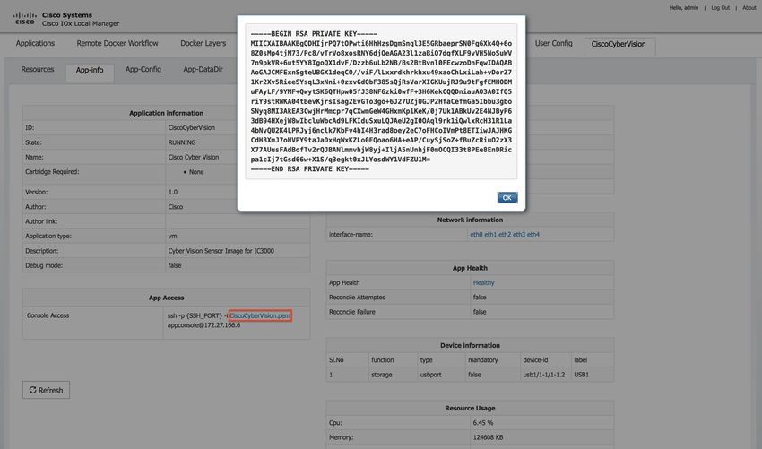
b) Get the private key of the container by going to Local Manager -> Application -> ->
Manage -> App Info -> *.pem file. Clicking on CiscoCyberVision.pem displays the contents of the
private key. See Figure 40: Click to Display Key, on page 40 and Figure 41: App info Page, on page 40.
Figure 40: Click to Display Key
Figure 41: App info Page
c) Save the private key by copying the entire content into the .pem file you created in Step
2a. Make sure to save the changes. For example:
Example:
Cisco IC3000 Industrial Compute Gateway Deployment Guide
40Additional Administration
Connecting to the Application Console using the Command Prompt/Terminal
Device$ vi CiscoCyberVision.pem -
Opens the file in the vi editor
*cut and paste the contents of the file into the open file*
Device$ wq -
Writes the file and quits the vi editor
Device$ cat CiscoCyberVision.pem -
Displays the contents of the file
d) Add the necessary permissions for the file. Recommended using "chmod 600". For example:
Example:
Device$pwd -
Prints the working directory
Desktop/pem_certificates
Device$ls -
Displays the contents of the directory
CiscoCyberVision.pem
Device$chmod 600 CiscoCyberVision.pem -
Changes the mode of the file to 600 which is more secure
e) If you see a warning as shown in Figure 42: Warning Message, on page 41 when trying to ssh to the
application console, it is because the current file permissions are too open.
Figure 42: Warning Message
Step 3 SSH to the Application Console.
a) Run the command that is found under the App info tab in the directory you saved the pem certificate: ssh
-p {SSH_PORT} -i .pem appconsole@169.254.128.2 {SSH_PORT} = 22
Figure 43: App Access
Step 4 You should now be able to navigate the app logs to begin troubleshooting.
Cisco IC3000 Industrial Compute Gateway Deployment Guide
41Additional Administration
Connecting to the Application Console using PuTTY
Connecting to the Application Console using PuTTY
PuTTY is an SSH and telnet client, developed originally by Simon Tatham for the Windows platform. PuTTY
is open source software that is available with source code and is developed and supported by a group of
volunteers.
Follow steps 1 and 2 under the Connecting to the Application Console using the Command Prompt/Terminal
, on page 39 before starting a PuTTY session.
On Windows, when you use PuTTY, first convert the .pem file to a PuTTY-compatible .ppk with the use of
PuTTygen.
Follow these steps:
Procedure
Step 1 Start PuTTygen by navigating to File > Load private key as shown in Figure 44: PuTTY Key Generator, on
page 42.
Figure 44: PuTTY Key Generator
Step 2 Set the file filter to All Files and open the downloaded .pem as shown in the following graphic.
Figure 45: File Filter
Step 3 Go to File > Save private key and save the .pem as .ppk as shown in Figure 46: Save Key, on page 43.
Cisco IC3000 Industrial Compute Gateway Deployment Guide
42Additional Administration
Connecting to the Application Console using PuTTY
Figure 46: Save Key
Step 4 Once you have the .ppk, start PuTTY and enter 169.254.128.2, port 22 in the session dialog. Next, go to
Connection - SSH - Auth and supply the private key file .ppk file as shown in the following graphic.
Figure 47: PuTTY Configuration
Step 5 Click Open in order to start the session. Enter the username appconsole as shown in the following graphic.
Cisco IC3000 Industrial Compute Gateway Deployment Guide
43Additional Administration
Audit Trail for Application Management Operations
Figure 48: PuTTY Session
Performing these steps should bring you to the application console of the running IOx container on the IC3000.
Audit Trail for Application Management Operations
Note This functionality is only supported in the IoT FND and Fog Director Integrated Solution.
The following two Application Management operations will generate an Audit Log:
• Install App
• Uninstall App
Note There is no audit trail to track when you import or delete an application to or from the IoT FND and Fog
Director Integrated Solution.
To view the Audit Log details, choose ADMIN > SYSTEM MANAGEMENT > AUDIT TRAIL.
Figure 49: Audit Trail
Note You can now import multiple versions of the same application.
Cisco IC3000 Industrial Compute Gateway Deployment Guide
44You can also read