2022 Briggs 206 Category Rules - Cornwall Motor Speedway
←
→
Page content transcription
If your browser does not render page correctly, please read the page content below
2022 Briggs 206 Category Rules

  Approved Engines: The Briggs & Stratton LO206 Canadian Engine is built for the Canadian
   market and has a unique technical specification. The only LO206
 engines that are eligible for Canadian competition are identified with a
   special embossed stamp on the engine block and cylinder head.
Engines that do not bear the official special embossed stamp cannot be
                                  used.

   •    The use of a Raceceiver and Steering Wheel Quick
        Disconnect is mandatory for all classes
   •    Classes:
        Box Stock (age 5-8) 225# must run Red Slide gear rule 13-62 no tach or steering fairing.   DRUM
        CLUTCH ONLY
        Junior 1 (age 8-10) 245# must run Green Slide
        Junior 2 (age 10-12) 275# must run Blue Slide
        Junior 3 (age 12-15) 300# must run Yellow Slide
        Senior Stock (age 15 & up) 350# must run Senior Black Slide
        *All classes must have rear bumper covering at least 1/2 of the two rear tires

*Note that the track has the right to make exceptions to what class a junior driver may race in
based on age and or experience for the safety of that driver as well as other competitors.

   •    Engine Components: Only the original equipment Briggs & Stratton LO206 #124332-
        8201 or #124332-8202 engine is allowed. All parts must be unaltered Briggs & Stratton
        LO206 parts specifically made for this engine by Briggs and Stratton. No aftermarket
        parts to be used. Both Briggs & Stratton engine seals (2 of them) must be present with
        both the fastener and seal in “as shipped” from the factory location and condition. Any
        defined tampering with the fasteners or damage to the wire/seal itself (example:
        delaminated hologram) are grounds for disqualification. Take proper care of your seals
        to ensure their integrity.
   •    Headers and Muffler: Header must be RLV Model 5506 or Model 5507 only. Exhaust
        header to cylinder bolts or nuts must be safety wired. Header support brace is
        mandatory. Additional bracing may not be welded to the pipe. Silencer must be only
        RLV B91XL, Part Number 4104, with round baffle holes only. Safety wiring of the
        silencer to header is mandatory. All 4 baffles must remain unaltered and the hole size
        can be verified using a no-go pin of .1295”. Exhaust gases may only exit through the
        muffler baffles. Muffler must be mounted on the header in a way that does not allow
        exhaust to leak at this joint. The exhaust header and silencer surfaces must be

   Rev: 310122                                                                                 Page 1 of 7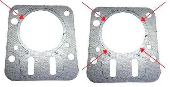
completely wrapped with non-asbestos insulation material starting approximately 3 to 4
inches from the exhaust flange.
• Fuel: Only Gasoline no greater than 94 octane sold at Canadian roadside fuel stations
open to the public. The addition of fuel additives is not permitted. No E85 Flex Fuel
permitted.
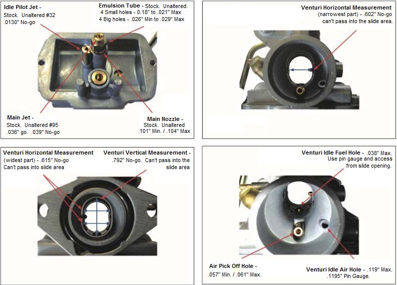
• Carburetor: Carburetor Venturi measurements are to be taken from both the inlet and
outlet sides of the Venturi. A slight chamfer around the choke bore ID (air horn) may be
present. 1.149” no go TECH TOOL A7. If a carburetor is suspect, Technical Inspectors
may also use any appropriate tool they see fit to make precise measurements. Any
carburetor that does not meet the Venturi specifications listed in these regulations is
deemed to be illegal. Slide must remain B&S stock unaltered. Slide cutaway to be
measured on flat surface. .075” no go Tech Tool A10. Idle pilot jet must remain
completely stock and clearly identified with its original etched or stamped ‘32’ as shipped
from B&S. Main jet must also remain completely stock and clearly identified with its
original etching or stamped ‘95’ as shipped from B&S. B&S stock unaltered aluminum
needle is required part number 555602 marked #BGB. Metal choke cover must remain
in place but may be secured with silicone or epoxy sealer. Additional pin punching is
allowed to tighten choke cover. Air must only enter the engine from the natural air filter
horn of the carburetor.
Rev: 310122 Page 2 of 7• Carburetor (Continued): The B&S stock carburetor part #555658 is the only carburetor
permitted. No alterations allowed unless stated on this page below. All parts will be
compared to a stock known B&S part for eligibility. This includes the nozzle, emulsion
tube, jets, float, float needle and all other carburetor parts. It is allowed to adjust the float
height by means of bending the small tab on the float arm.
o All Classes EXCEPT Senior Stock
Require the installation of the locking cap Part #555726 on the carburetor
slide cover. It is not permitted to run the classes without the specified
slide and locking cap. The locking cap must be tightened.
Carburetor Slide Optimization: Optimization of the slide opening
is permitted. The only allowable method of slide
optimization is by removing material from the
throttle cap in the area shown in the graphic on
the right. Slide opening must not exceed the
appropriate “no go” specification as per class
regulations.
CAUTION – The risk of exceeding the allowable limit on
the slide opening could lead to an unnecessary DQ.
• Fuel Pump: The only fuel pump, B&S part number 808656, is legal for competition. All
other pumps are prohibited. It is prohibited to pulse from the intake manifold.
Spacing of the Fuel Pump must be less than .75” off of the control
plate, B&S #555699, Measurement is from the base of the
control plate to the bottom of the fuel pump. Vertical mounting
or mounting the fuel pump upside down is NOT allowed.
The fuel pump must be pulsed from a pulse fitting mounted
on the oil fill fitting located on the engine side cover.
Aftermarket one-piece filler/pulse fittings such as shown on
the right are permitted. A fuel pump return line to the fuel tank is
prohibited. Use of an inline fuel filter is highly recommended. Only a single fuel filter is
allowed. It can only be mounted inline between the fuel tank and fuel pump. The fuel
filter itself is a non-tech item.
Rev: 310122 Page 3 of 7• Air Filter: The only air filter permitted is the Briggs and Stratton Green Air Filter
#555729. No modification to the filter element is permitted. The addition of Briggs and
Stratton pre-filter #557096 only is allowed.
• Crankcase and Carburetor Breather Catch Containers: A crankcase overflow tube must
be fitted. A carburetor overflow tube must be fitted. Both tubes must run to a securely
mounted catch container. The catch-container must be vented to atmosphere.
• Cylinder Head: The ONLY head casting for the LO206 is the ‘RT-1’, cast into the head
just off the head gasket surface (towards the rear of the engine, PTO side). The overall
head thickness is 2.430”. Cylinder head must be "as cast". Factory machining marks left
on the head are technical inspection items. Hard carbon may be scraped from head
before measuring. Depth of shallow area of combustion chamber must be .030 inch
minimum. This measurement to be taken with a depth gage on both the combustion side
and spark plug side of cylinder head. Depth at floor of combustion chamber is .341”
minimum. No deburing, machining, honing, grinding, polishing, sanding, media blasting,
etc. The transition from intake bowl to port must have factory defined machining burr at
this junction. No addition or subtraction of material in any form or matter. No alterations
of any kind may be made to the intake or exhaust ports. Intake Port: Maximum diameter
measurement: 0.918” max. Tech Tool A6. Exhaust Port AS CAST. Exhaust Outlet:
0.980” – Tech Tool A6.
• Head Gasket: Unaltered B&S part #555723 is the only head gasket allowed. Minimum
thickness allowed is .049". Measurement must be performed using a micrometer.
Readings are taken from inside the cylinder hole of the gasket closest to the combustion
chamber (see diagram). Four measurements must be taken with 3 meeting the minimum
thickness of .049”.
Rev: 310122 Page 4 of 7• Valve Train: Valve maintenance permitted (valve job). Valve seats must remain with the
factory specification of 30 and 45 degree angles only. Valve seats of additional angles
and/or excessive material removed when compared to the factory stock is prohibited.
Intake valve seat diameter inside: 0.972”.Tech Tool A2. Exhaust valve seat diameter
inside: 0.850”. Tech Tool A1. Replacement of valve guides with Briggs & Stratton part
#555645 only is allowed. Maximum depth from the head gasket surface to the intake
valve guide is 1.255”. Briggs & Stratton heat disperser, P/N 555690 can be installed in
the exhaust bolt boss per factory instructions. Retainer flange thickness 0.055” to 0.075”
maximum. Both intake and exhaust must have OE stock Briggs & Stratton valve
keepers. No machining, polishing, easing, or titanium valves allowed.
Only unaltered Briggs & Stratton part #555552 (exhaust) and #555551 (intake) valves
permitted.
Intake Valve
Minimum Weight of Valve 27.8 grams
Diameter of valve stem .246” to .247”
Diameter of valve head 1.055” - 1.065” Tech Tool A17
Diameter of valve seat .972” ID Maximum
Valve length Minimum 3.3655”
Height from angle of valve face to top of the valve .057” Minimum Tech Tool A26
Exhaust Valve
Minimum Weight of Valve 27.2 grams
Diameter of valve stem .246” to .247”
Diameter of valve head .935” to .945” Tech Tool A18
Diameter of valve seat .850” ID Maximum
Valve length Minimum 3.3655”.
Height from angle of valve face to top of the valve .060” Minimum Tech Tool A27
Valve Springs are single coil stock, unaltered Briggs & Stratton part # 26826. Must be
identical in appearance to factory part and have 4.00 to 4.75 coils in stack. Spring Wire
Diameter: .103” to .107”. Valve spring length: .930” max – Tech Tool A15. Inside
diameter: .615” to .635”.
Rocker Arms must be stock B&S part # 555711 or #797443 and may not be altered in
any way. Rocker arms must be stamped with B&S Logo. Rocker arm overall length -
2.820” min. Rocker arm #555711(U.S.) must be used with rocker stud #694544(U.S.).
Rocker arm #797443(metric) must be used with rocker stud #797441(metric).
Rocker studs must be stock, unaltered B&S part #694544 U.S. (1/4-28 thread) or
#797441 Metric (M8 x 1.00 thread) and in stock location.
Rocker Ball must stock Briggs & Stratton. Diameter .590” min. to .610” maximum. Tech
Tool A16. Rocker arm mounting positions may not be altered in any manner. No
helicoiling of mounting holes. No bending of studs.
Rocker arm stud plate must be bolted to the head with one, OEM stock Briggs & Stratton
gasket only - no alterations. Maximum thickness of gasket is .060”. Rocker plate to head
fastener holes must remain stock .289” max. Rocker arm – overall length 2.820”
minimum.
Rev: 310122 Page 5 of 7• Valve Train (Continued): Must be unaltered stock Briggs & Stratton part #555531. b.
Push rod length 5.638 minimum inches to 5.658” maximum. Tech Tool A5. Push rod
diameter .185” minimum to .190” maximum.
• Flywheel: Stock Briggs & Stratton part #555683 only. No modifications are allowed to
the flywheel. The minimum weight of the flywheel, fins and attachment bolts is 4 pounds
1 ounce. No machining, glass beading, sand blasting, painting or coating of flywheel is
allowed. A flywheel fan, Briggs & Stratton part #692592, with broken fins must be
replaced.
• Ignition System: Stock, unaltered flywheel key with the Briggs & Stratton logo is
required. Width of the key allowed is .1825”-.1875”. No offset keyways allowed.
Unaltered Briggs & Stratton stock ignition part #555718 is mandatory. Only “GREEN”
ignition module allowed. Maximum RPM: 6,150. Coil or its position, other than air gap
may not be altered in any way. Coil mounting bolts must be stock and cannot be altered
in any way to advance or retard timing. Attachment bolts and/or bolt holes may not be
altered.
Spark Plug Options:[1] B&S unaltered factory spark plug part number #555737
Champion RC12YC with Briggs Logo on Insulator or [2] AutoLite AR3910X unaltered
OEM spark plug (B&S P/N #84005196) “AutoLite” and “AR3910X”
identification on the insulator is permitted. Spark plug must have the
“AutoLite” and “AR3910X” identification on the insulator is permitted. Sealing
washer must be in place as from factory. Only the OEM Briggs & Stratton part #555714
Spark Plug Boot is permitted. The Briggs & Stratton ignition switch and wires must
remain in stock location. It is not permitted to alter the OEM wiring.
• Starter: Only Briggs & Stratton part # 695287, must be intact. Starter maybe rotated. No
taping or covering of the rewind shroud is permitted.
• Shrouds & Covers: All pieces of the engine cooling shroud/blower housing and control
panel must be stock Briggs & Stratton and properly installed. Engine Shroud may be
painted any color. Engine shroud, covers, and control panel must be intact and not
modified. Any bolt, with the exception of the head bolt and blower housing, that is used
to secure sheet metal shrouds and covers may be replaced with larger diameter bolts.
• Use of Helicoils: It is permitted to use Helicoil thread inserts for shrouds, valve cover, oil
drain, oil fill holes, blower housing, and exhaust pipe attachment studs on the head and
lower brackets.
• Clutch: Open to any centrifugal drum or dry disc clutch. (Except for Box Stock where
ONLY DRUM CLUTCH is Allowed)
Rev: 310122 Page 6 of 7The Technical Officials may at their sole discretion, at any time, replace a competitor's sealed
engine or component thereof. Failure to comply is grounds for exclusion.
These Regulations are the Only Regulations for the L0206 component. Only the Briggs &
Stratton Racing Department in Milwaukee can make changes to the technical specifications
herein, provided they are first approved by ASN Canada FIA.
Changes, corrections, addendums, etc. will be published only by ASN Canada FIA and become
effective on a date specified.
The manufacturer Briggs & Stratton and their dealers and their agents are not authorized to
alter, verbally or otherwise, any rule herein. Should any Briggs & Stratton literature, catalogues,
manuals, videos, etc. be different than these regulations, these regulations take precedence.
Any rules published by Briggs & Stratton for use in other countries are not applicable in Canada.
Unless these rules state that you can do it, you cannot do it.
The LO206 genuine engine products and service parts are available only through the Canadian
distributor and authorized Canadian dealers. Engines, and parts thereof new or used,
purchased from private sources may not meet these regulations and may not pass Technical
Inspection at an event.
Enquiries can be addressed to:
Power Source Canada
2815 Bristol Circle, Unit 1
Oakville, ON Canada L6H 6X5
Tel 905-829-0006
Fax 905-829-8611
Email info@powersourcecanada.ca Toll Free Customer Service: 1-800-663-9700
Please note that these rules are general guidelines. If you are chosen for tech, please do so without
confrontation. Refusing tech will result in you being suspended for the next 2 complete race events (rain
outs do not count toward the suspension). If any confrontation is given you will forfeit your finish and
point for the day. If chosen, please take kart directly to the designated tech area where there will be a
track official to watch your equipment. No work may be performed on kart at this time. Driver/owner of
kart being teched and tech official only permitted in the tech area during tech sessions. It is not the
responsibility of the tech inspector to reassemble engine post tech. If you are deemed illegal you will be
given “one week” to correct any illegal findings. First offence you will forfeit your finish and points for the
day. Second offence forfeits finish and points and will not be permitted to race next scheduled race day
(rain outs do not count towards the suspension). Third offence to be determined by track owner. Any
issues that are questionable will be discussed by the tech inspector and track owner and decision will be
made in the best interest of both parties.
Rev: 310122 Page 7 of 7You can also read