USER and MAINTENANCE MANUAL - P.D. Meters BM Series MA/0004/00/EN/12 rev. 07/2020 - Hermann Ehlers GmbH
←
→
Page content transcription
If your browser does not render page correctly, please read the page content below
USER and
MAINTENANCE MANUAL

                                                          P.D. Meters
                                                           BM Series
                                                               MA/0004/00/EN/12
                                                                    rev. 07/2020

An der Autobahn 45 · 28876 Oyten · Tel. +49 420791210 · Fax +49 4207912141
     Email sales@EhlersGmbH.de · Home https://www.EhlersGmbH.com
FOREWORD
All rights reserved. This manual may not be reproduced, distributed, translated into other languages or transmitted
in any form or by any means, including photocopying, recording or any other storage and retrieval system,
whether electronic or mechanical, for purposes other than the purchaser’s personal use without express written
permission of the Manufacturer. The Manufacturer is not liable for any consequences of incorrect operation
carried out by the user.

GENERAL CONSIDERATION
All operating and maintenance instructions and recommendations described in this manual must be respected.
The Manufacturer recommends regular cleaning and maintenance to keep the device in the best conditions and
achieve optimal results. Training of the user is of particular importance, both as regards the use of the equipment,
and for maintenance and compliance with the operating procedures and all the safety standards indicated in this
manual. In any case, the Manufacturer is always available for any clarif cation or further information.

Isoil Impianti S.p.A. reserves the right to update and improve the products without obligation of notice and notif cation.
Isoil Impianti S.p.A. is not liable for the use of data that may have been modif ed.

         ISOIL IMPIANTI S.p.A. ALL RIGHTS RESERVED
 2/42    REPRODUCTION OF THIS MANUAL IS FORBIDDEN                                                  MA/0004/00/EN/12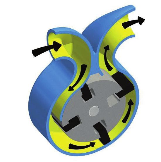
1.          INTRODUCTION..........................................................................................................................................5
     1.1.        Identification of the device ..................................................................................................................................................... 5

              1.2. Name plates and labels .....................................................................................................................................................................5
     1.3.        EU conformity declaration ..................................................................................................................................................... 6
     1.4.        Warranty ................................................................................................................................................................................. 6
            1.4.1. Validity.................................................................................................................................................................................................6
            1.4.2. Conditions...........................................................................................................................................................................................6
            1.4.3. Exclusions and limitations..................................................................................................................................................................6
2.          GENERAL SAFETY PRINCIPLES ...............................................................................................................7
     2.1.        General instructions ............................................................................................................................................................... 7
     2.2.        Device operation .................................................................................................................................................................... 7
     2.3.        Instructions for the operator................................................................................................................................................... 7
     2.4.        Maintenance instructions ....................................................................................................................................................... 8
     2.5.        Explosion protection instructions ........................................................................................................................................... 9
            2.5.1. Temperature class..............................................................................................................................................................................9
3.          TECHNICAL DESCRIPTION .....................................................................................................................10
     3.1.        Intended use......................................................................................................................................................................... 10
     3.2.        Main components................................................................................................................................................................. 10
            3.2.1. Working principle..............................................................................................................................................................................11
4.          INSTALLATION AND OPERATION ............................................................................................................12
     4.1.        Handling ............................................................................................................................................................................... 12
            4.1.1. Weights and packaging ...................................................................................................................................................................12
     4.2.        Installation requirements...................................................................................................................................................... 12
     4.3.        Installation............................................................................................................................................................................. 13
            4.3.1. Pump installation ..............................................................................................................................................................................14
5.          MAINTENANCE .........................................................................................................................................15
     5.1.        Ordinary maintenance ......................................................................................................................................................... 15
            5.1.1. General revision checks ..................................................................................................................................................................16
     5.2.        Extraordinary maintenance ................................................................................................................................................. 16
     5.3.        Disassembly ......................................................................................................................................................................... 16
            5.3.1. Vanes disassembling .......................................................................................................................................................................17
            5.3.2. Reassembly......................................................................................................................................................................................17
     5.4.        Calibrating mechanism (for mechanical counter only) ...................................................................................................... 18
            5.4.1. Flow meter calibration .....................................................................................................................................................................18
     5.5.        Suggested lubricating oils for calibrating mechanism ........................................................................................................ 19
     5.7.        Storage ................................................................................................................................................................................. 20
     5.8.        Spare Parts .......................................................................................................................................................................... 20
     5.9.        Troubleshooting.................................................................................................................................................................... 21
6.          SPECIAL TOOLS .......................................................................................................................................22

                                                                                                                                    ISOIL IMPIANTI S.p.A. ALL RIGHTS RESERVED
      MA/0004/00/EN/12                                                                                                            REPRODUCTION OF THIS MANUAL IS FORBIDDEN                                          3/42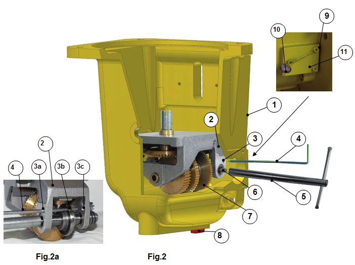
ATTACHMENTS

BM 200 WITH MECHANICAL COUNTER OVERALL DIMENSIONS........................................................................dwg.7885/M

BM 400 WITH MECHANICAL COUNTER OVERALL DIMENSIONS....................................................................... dwg. 7886/M

BM 600 WITH MECHANICAL COUNTER OVERALL DIMENSIONS....................................................................... dwg. 7887/M

BM 200 WITH PULSE EMITTER OVERALL DIMENSIONS.....................................................................................dwg.7885/1M

BM 400 WITH PULSE EMITTER OVERALL DIMENSIONS................................................................................... dwg. 7886/1M

BM 600 WITH PULSE EMITTER OVERALL DIMENSIONS................................................................................... dwg. 7887/1M

BM 200 ASSEMBLY..................................................................................................................................................dwg.6980/M

BM 400 ASSEMBLY................................................................................................................................................. dwg. 6254/M

BM 600 ASSEMBLY................................................................................................................................................. dwg. 6979/M

MECHANICAL SEAL...............................................................................................................................................dwg. 5649/M

MAGNETIC TRANSMISSION..................................................................................................................................dwg. 6478/M

CALIBRATION MECHANISM.....................................................................................................................................dwg.672/M

GLOSSARY SYMBOLS

The instructions in this manual may be accompanied by the following pictograms:

                          SYMBOL                                                       MEANING

                                                Safety instruction: failure to observe may result in a dangerous
                                                situation

                                                Important tips and recommendations

                                                Prohibition

                                                Remarks about maintenance

            ISOIL IMPIANTI S.p.A. ALL RIGHTS RESERVED
  4/42      REPRODUCTION OF THIS MANUAL IS FORBIDDEN                                                                                        MA/0004/00/EN/12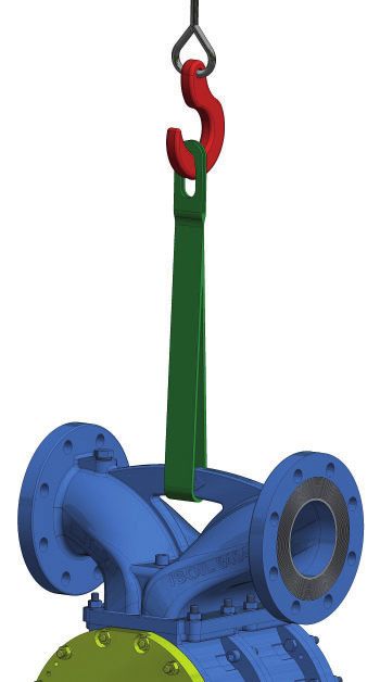
1. INTRODUCTION                                                            ISOIL
                                                                           I   M   P   I   A   N   T   I

1.1.      IDENTIFICATION OF THE DEVICE
                         DEVICE                                                        TYPE
                         P.D.METER                                         BM 200/400/600

The following name plate is permanently fixed on the device .

                                      *                               11

                                          1              2                 3

                                          4                            5
                                          6                            7
                                          8                            9
                                                    10

  *      In case of CE marking only
  1.     ITEM: p.d. meter model
  2.     YEAR: production year
  3.     S/N: serial number
  4.     TS: design temperature range
  5.     DN: nominal diameter
  6.     PS: maximum design pressure
  7.     FLOW RATE MIN: minimum flow rate of the p.d. meter
  8.     PT: test pressure
  9.     FLOW RATE MAX: maximum flow rate of the p.d. meter
  10.    FLUID: product
  11.    Manufacturer information

           Data field layout in the name plate may change.
           When ordering please specify serial number and type/model of device.

1.2.1.    NAME PLATES AND LABELS
On the device there may be warning labels or name plates indicating the correlation between the meter and
its electronic counter. When required, metric plates are fixed on the device according to PED, ATEX or MID
standards.

                                                                   ISOIL IMPIANTI S.p.A. ALL RIGHTS RESERVED
      MA/0004/00/EN/12                                           REPRODUCTION OF THIS MANUAL IS FORBIDDEN      5/42
1.3.     EU CONFORMITY DECLARATION
The EU conformity declarations are supplied separately but they are to be considered as an integral part of this
service and operator’s manual

1.4.     WARRANTY
1.4.1.   VALIDITY

Devices are guaranteed for twelve months after the delivery date unless otherwise agreed in the purchasing
order.

1.4.2.   CONDITIONS

The warranty covers only manufacturing or manufacturing defects and does not cover damage due to wear,
dirt, modif cations or variations of the instrument not authorized by Isoil Impianti S.p.A.. The replacement under
warranty of the defective parts is made ex works.

1.4.3.   EXCLUSIONS AND LIMITATIONS

Warranty is valid only if original spares are used and it is null and void in case of improper use or when the
technical specif cation of the instrument are not respected. Isoil Impianti S.p.A is the sole authority with the right
to decide if the warranty can be applied. If the supply contract provides for different warranty conditions, the
standard warranty conditions will be exceeded by those agreed upon in the purchasing order.

         ISOIL IMPIANTI S.p.A. ALL RIGHTS RESERVED
 6/42    REPRODUCTION OF THIS MANUAL IS FORBIDDEN                                               MA/0004/00/EN/12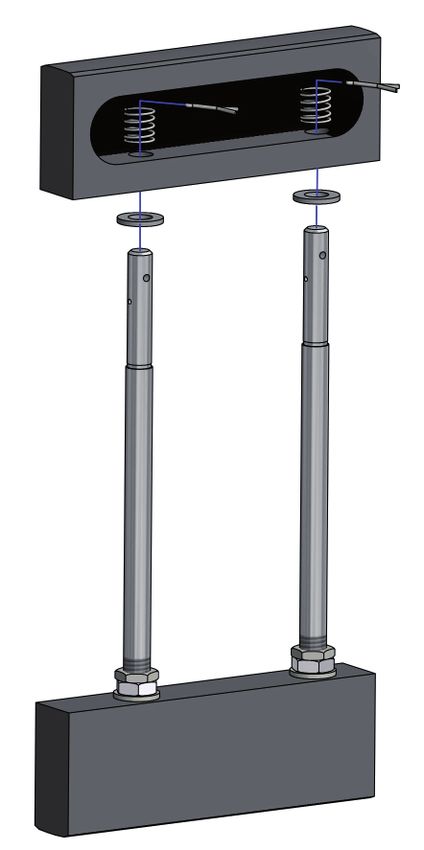
2. GENERAL SAFETY PRINCIPLES
This operator’s manual contains basic safety instructions that must be followed during system installation,
operation and maintenance. Failure to comply with these instructions may result in personal injury and can lead
to personal, industrial or environmental accidents.

Some examples of possible hazards caused by non-compliance with these instructions are:

•           Failure of the system and/or of its components.
•           Damages to people caused by exposition to electrical, mechanical or chemical hazard.
•           Pollution of the environment due to the leaking of hazardous substances.

Carefully follow the safety instructions described in this manual; in case of doubt, please contact the Manufacturer.

2.1.        GENERAL INSTRUCTIONS

    •     Carefully read the User and Maintenance Manual.
    •     Make sure that all the personnel assigned to the installation, operation and maintenance is properly trained.
    •     Make sure that the contents of the User and Maintenance Manual are completely understood by all
          personnel assigned to the operations on the system.
    •     Inspect parts under pressure in compliance with national regulations before the installation of the system.
    •     Make sure that a copy of the User and Maintenance Manual is available to the personnel on site.
    •     Make sure that the system operates in compliance with the relevant operational limits.
    •     The operators must also adhere to the national laws and to the safety, accident prevention and environmental
          protection regulations applicable to the location and f eld in which the devices are used.

2.2.        DEVICE OPERATION

    •     The device must be operated exclusively by the personnel trained and authorized to its operation
    •     The device must not be operated in presence of foreign, unauthorized or not adequately trained personnel.
    •     The device must be used only for the purposes it was made for; the manufacturer is not responsible for any
          damage resulting from failure to comply with the conditions of use.
    •     The device must be operated only within the technical limits described in the User and Maintenance
          Manual; the Manufacturer is not responsible for any damage resulting from failure to comply with the
          operational limits

2.3.        INSTRUCTIONS FOR THE OPERATOR

    •     The operator must not, on own initiative, carry out any operation that is outside his competence.
    •     The operator must carefully comply with all the safety instructions contained in this manual.
    •     Do not use petrol, solvents or other f ammable substances to clean the device or its parts. Use only
          approved commercial solvents that are non-f ammable and non-toxic.

                                                                        ISOIL IMPIANTI S.p.A. ALL RIGHTS RESERVED
        MA/0004/00/EN/12                                              REPRODUCTION OF THIS MANUAL IS FORBIDDEN      7/42
2.4.     MAINTENANCE INSTRUCTIONS

  •     Carefully read the name plates on each part of the equipment.
  •     All maintenance operations, either ordinary or extraordinary, must be performed by authorized and trained
        personnel.
  •     The maintenance operator must wear adequate clothing according to the working environment and to the
        situation: loose or voluminous clothes, chains, bracelets, rings, earrings or anything that might get caught
        in the mechanical parts of the system must be avoided.
  •     The maintenance operator must wear adequate protective devices in accordance with safety and accident-
        prevention regulations.
  •     In explosive environments use only anti sparking equipment.

As an example, basic individual protections are indicated below.

                                   PERSONAL PROTECTIVE EQUIPMENT

                                                      Protects from elements or substances that may fall
                      Safety helmet
                                                      from above or from possible risks of collision

                                                      Appropriate clothing e.g.: to protect from getting caught
                      Work clothes
                                                      in any moving part of a device or of the plant

                                                      Protect eyes from any contact with hot or corrosive
                      Safety goggles
                                                      substances

                                                      If there is a danger of injury to the hands due to very
                      Safety gloves
                                                      hot substances and / or corrosive or sharp parts

                                                      Protect from the fall of heavy elements and from hot or
                      Safety boots
                                                      corrosive substances

                  Carefully check that the system and its parts are not under pressure before disassembling
                  the equipment or its accessories for inspection, maintenance or replacement of
                  components.
                  Also make sure that all electric or electronic part, if any, are disconnected from their power
                  supply.

          ISOIL IMPIANTI S.p.A. ALL RIGHTS RESERVED
 8/42     REPRODUCTION OF THIS MANUAL IS FORBIDDEN                                             MA/0004/00/EN/12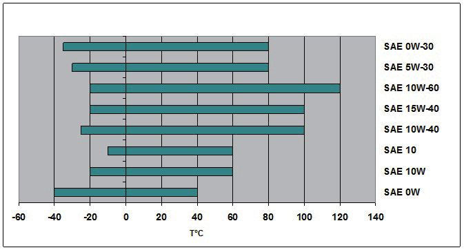
2.5.     EXPLOSION PROTECTION INSTRUCTIONS

                When working in potentially explosive atmospheres, carefully follow the explosion
                protection instructions indicated in this chapter.

In potentially explosive atmospheres only use explosion-proof components provided with specif c identif cation
and suitable for such application.
According to EU Directive 2014/34/EU (ATEX) the Ex protection is valid only if the p.d. meter is used in compliance
with the instructions at par.3.1 (intended use).

                         Never exceed (above or below) the limits indicated on the device name plate.

                          Absolutely avoid unauthorized operation modes.

2.5.1.   TEMPERATURE CLASS

ATEX Marking: Ex II 2 G Ex h IIB T6...T4 Gb.

Temperature classes according to the maximum liquid temperature are indicated in the following table:

                  MAX ALLOWED TEMPERATURE                          TEMPERATURE CLASS
                          OF THE LIQUID
                                                          ACCORDING TO ISO 80079-36 DIRECTIVE
                              100 °C                                           T4
                               70 °C                                           T5
                               50 °C                                           T6

                                                                     ISOIL IMPIANTI S.p.A. ALL RIGHTS RESERVED
    MA/0004/00/EN/12                                               REPRODUCTION OF THIS MANUAL IS FORBIDDEN      9/42
3. TECHNICAL DESCRIPTION
3.1.        INTENDED USE

ISOIL positive displacement meters are precision measuring instruments designed for use with a variety of
petrochemical products and liquids. Each meter is tested and calibrated in the factory before shipment.

A good and regular maintenance ensures perfect operation with high precision over time.

The equipment has been designed and built to operate safely but it is necessary to comply with the following
indications:

  •        Use it within the technical limits indicated on the contract and/or in this manual;
  •        Follow the procedures mentioned in this manual;
  •        Do not exceed maximum pressure and f ow rate indicated on the label;
  •        Use the special tools to perform all the assembling / reassembling procedures;
  •        Schedule ordinary maintenance (periodic check with proving tanks);
  •        Perform extraordinary maintenance promptly if necessary;
  •        Do not disable safety devices.

3.2.        MAIN COMPONENTS

P.d. meters are composed of the following parts, as shown in f g.1.

       1       Manifold
       2       Body
       3       Rotor
       4       Vanes

                                                                                   1

                                                         2                                       4

                                                             3

                                                                          Fig.1

             ISOIL IMPIANTI S.p.A. ALL RIGHTS RESERVED
 10/42       REPRODUCTION OF THIS MANUAL IS FORBIDDEN                                                MA/0004/00/EN/12
3.2.1. WORKING PRINCIPLE
P.d. meters are measuring instruments for liquids.
Fluid enters the meter trough the manifold thus exerting pressure on the vanes and rotating the rotor inside the
measuring chamber.
Since the measuring chamber has a f xed and known volume for each meter type, f owing liquid can be measured
by multiplying the number of rotor rotations by the measuring chamber volume.
The meter is equipped with a counter, either mechanical or electronical, in order to calculate the number of
rotations and the total f ow.
3.3. OPERATING PRECAUTIONS
The meter must be calibrated following the instructions of the User Manual and in the Manual of Petroleum
Measurement Standards (API) with particular attention to the following chapters:
- Chapter 4: “Proving systems”
- Chapter 5: “Metering”
- Chapter 6: “Metering assemblies”
- Chapter 11, section 2.3: “Water calibration of volumetric provers”
- Chapter 12, section 2: “Calculation of petroleum quantities”.
ISOIL IMPIANTI S.p.A. ALL RIGHTS RESERVED
MA/0004/00/EN/12 REPRODUCTION OF THIS MANUAL IS FORBIDDEN 11/424. INSTALLATION AND OPERATION
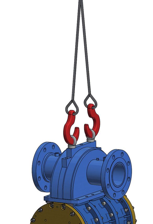
4.1. HANDLING
Handle the P.D Meter with a suitable lifting
device: use straps / ropes of appropriate
length and capacity by positioning them as
shown in the f gure.
BM 200 - BM 400 BM 600
4.1.1. WEIGHTS AND PACKAGING
The weights and dimensions are purely indicative and refer to standard bare shaft conf guration.
Flanges Weight
Type
ANSI 150 RF (kg)
BM 200 3” 70
BM 400 4” 108
BM 600 6” 155
During shipment, the electrical and process connections are protected by special plugs.
These must not be removed until installation in the system.
4.2. INSTALLATION REQUIREMENTS
• The material and equipment operating conditions must be compliant with plant and environmental
requirements. Please check the data on the nameplate.
• Root valves installation at the inlet and outlet is recommended to ease servicing operations.
The device is not suitable for installation in plants where vibrations are transmitted along
the pipes. Under these conditions, the customer must provide for an adequate system of
staffing of the pipes and, if necessary, a damping system.
Flow through the meter must be regular and uniform: avoid pulsating and irregular f ow.
ISOIL IMPIANTI S.p.A. ALL RIGHTS RESERVED
12/42 REPRODUCTION OF THIS MANUAL IS FORBIDDEN MA/0004/00/EN/12Before installation of the p.d. meter ,cleaning of the plant pipings is suggested to remove
dirt and foreign particles, especially in the case of a new plant.
Leave enough space around the device to easily perform commissioning, servicing and
disassembly
If the device is installed in a section of pipe intercepted by two valves, this section must be
protected by an adequate thermal relief valve against the thermal expansion of the liquid.
4.3. INSTALLATION
The installation must be performed by qualif ed personnel who have read and understood
the maintenance and operator’s manual.
USER GUIDELINES
WARNING
For p.d. meters with
mechanical counter only
10PO
WATER MUST NOT ENTER THE METER
Make sure that the f ow direction through the device is the same indicated by the arrow on the
device itself.
The line upstream of the meter must always be full of product to avoid air from entering the meter’s
measuring chamber. If the pipe allows reversal f ow, a non-return valve must be installed.
In the event that the f ow rate of the line exceeds the maximum f ow rate of the volumetric meter, it
is necessary to install a f ow limiting valve downstream of the meter itself.
ISOIL IMPIANTI S.p.A. ALL RIGHTS RESERVED
MA/0004/00/EN/12 REPRODUCTION OF THIS MANUAL IS FORBIDDEN 13/42To protect the meter from possible damages due to foreign particles in the product, install a suitable
strainer with correct mesh type upstream of the meter.
MESH VISCOSITY MESH VISCOSITY MESH VISCOSITY
40 20 -150 cSt 60 6 - 20 cSt 100 < 6 cSt
BM p.d. meters can be installed horizontally or vertically. In both cases the rotor axis must be kept horizontal.
• To ensure the seal between f ange and pipe a gasket must be inserted between the f anges. The gasket
must be suitable to the product.
Check that the connections between the equipment are adequately tight. The connected
pipes must not exert any force/load on the device: the device is designed to support only
its weight, the pipes or other devices connected to it must be equipped with appropriate
supports.
Meters must be installed in such a way that air or vapor cannot enter the liquid under
measurement. It is suggested to install an air separator upstream of the meter.
When starting the equipment for the f rst time, slowly f ll it in with operating f uid as follows:
• Slowly open the upstream isolation valve;
• Slowly open the downstream isolation valve making f ow rate rise smoothly to the operating value.
4.3.1. PUMP INSTALLATION
Carefully follow the recommendations of the Manufacturer:
• In order to minimize problems due to air and vapors when installing pumps,pay particular attention to
factors such as the use of foot valves, inlet pipes dimension and conformity with NPSH when there are
suction pumps.
• For f ashing of liquids (quick gasif cation of the liquid) or easily vaporising liquids at high environmental
temperatures, e.g. light hydrocarbon, it is advisable to use submerged or submersible aspirations and
pipes larger than the nominal dimension of the pump.
ISOIL IMPIANTI S.p.A. ALL RIGHTS RESERVED
14/42 REPRODUCTION OF THIS MANUAL IS FORBIDDEN MA/0004/00/EN/125. MAINTENANCE
Maintenance includes interventions (inspection, verif cation, control, adjustment and replacement) that become
necessary due to normal use of the device.
Maintenance personnel must be well trained and must perform all work carefully, adhering
to all necessary safety measures. Non-authorized personnel must not stay in the working
area during maintenance operations.
Maintenance operations can be divided operationally into two main categories:
All those operations that the operator must carry out, preventively, to ensure
Ordinary maintenance
correct operation over time
Extraordinary maintenance All those operations that the operator must carry out when the device needs it.
Before removing the device from pipeline for any repair, check the Troubleshooting table in this manual.
When starting the equipment after any maintenance, slowly f ll it in with operating f uid as
follows:
• Slowly open the upstream isolation valve;
• Slowly open the downstream isolation valve making f ow rate rise smoothly to the operating
value.
5.1. ORDINARY MAINTENANCE
The maintenance table reported below is purely indicative. The user must def ne a maintenance schedule
according to the real operating conditions of the device.
Servicing intervals may greatly vary depending on the product, the environmental conditions, the actual workload,
the operating conditions etc.
Isoil Impianti S.p.A. accepts no responsibility for the breach of the instructions of use mentioned in this manual.
DEVICE MONTHLY 6 MONTHS 12 MONTHS 24 MONTHS
Meter CV
Body, rotor and vanes inspection Rev
CV: Visual inspection
Rev.: General revision check
ISOIL IMPIANTI S.p.A. ALL RIGHTS RESERVED
MA/0004/00/EN/12 REPRODUCTION OF THIS MANUAL IS FORBIDDEN 15/425.1.1. GENERAL REVISION CHECKS
The following list for meter check is purely indicative and it is the result of our experience in the f eld.
Proceed as follows:
COMPONENT REVISION CHECK
Turn rotor shaft in the opposite direction to the arrow on the manifold by using
the special tool. the rotor must rotate without any problem.
Body
Check status of bearings.
Check status of the gaskets and their slots.
Check if the gears work properly.
Check the oil level.
Calibrating mechanism
Visually inspect the calibrating mechanism for integrity (i.e. breaking of gear-
teeth or pins).
Check if vanes are damaged or worn out.
Rotor/ vanes
If so, replace them.
5.2. EXTRAORDINARY MAINTENANCE
The user must def ne a maintenance schedule according to the f uid used, the operational conditions, the
estimated/actual workloads and the environmental conditions.
For all extraordinary maintenance needed after a failure and/or a fault preventing normal operation of the system,
please contact the Customer Care Department of Isoil Impianti S.p.A..
5.3. DISASSEMBLY
All parts under pressure must be released before disassembling the meter or its accessories
for adjustment inspection, servicing or substitution of its components.
Also make sure that all electric or electronic parts, if any, are disconnected from their power
supply.
For maintenance operations and spare parts ordering, see attached drawings.
Gaskets dimensions may be altered due to contact with operating f uid.
We suggest to always have a gasket kit when performing maintenance operations.
ISOIL IMPIANTI S.p.A. ALL RIGHTS RESERVED
16/42 REPRODUCTION OF THIS MANUAL IS FORBIDDEN MA/0004/00/EN/125.3.1. VANES DISASSEMBLING
NOTE: Never remove the vanes unless they are damaged or worn out.
Vanes are not interchangeable and, if they can be reused, they must be placed in their original position.
Marking each vane and each slot will therefore ease the reassembling procedure.
Vanes disassembling can be performed as indicated in the table: refer to the drawing below.
A
UPPER VANE
C
D
B
LOWER VANE
Step Action
1 Mark each vane and each corresponding slot in the rotor.
Remove the split pins (pos. A) on the upper vane
2 Do not loosen or remove the vanes adjusting nuts (pos.B).since vanes clearance inside the measuring chamber
may change.
3 Remove the upper vane and its springs.
4 Remove the two washers (pos.C). Keep the washers in the original position and do not turn them upside down.
5 Extract the lower vane from the rotor together with its tie-rods (pos. D).
Do not trade places of the vanes tie rods.
5.3.2. REASSEMBLY
Reassembly is the exact reversal of the disassembling procedure.
ISOIL IMPIANTI S.p.A. ALL RIGHTS RESERVED
MA/0004/00/EN/12 REPRODUCTION OF THIS MANUAL IS FORBIDDEN 17/425.4. CALIBRATING MECHANISM (FOR MECHANICAL COUNTER ONLY)
The calibrating mechanism includes a group of gears which transmits movement from the rotor to the counter.
Operational failures of this mechanism are rare and they generally include breaking of tension pins due to an
excessive strain.(see dwg.672/M).
It is recommended to carry out repairs without changing the calibration setting.
5.4.1. FLOW METER CALIBRATION
To carry out meter calibration follow the procedure indicated here below (see Fig.2):
Step Action
a. Remove the plug (pos.8) under the housing (pos. 1) and drain the lubricant oil;.
b. Break and remove seals (pos. 10) on the cover (pos. 11);
Remove the three screws (pos. 9) securing the cover to the housing (pos. 1) in which calibrating mechanism is
c.
f tted (pos. 7);
d. Remove cover (pos. 11);
By using a square key (4 mm) (pos. 5) turn the shaft (6) till the holes (pos. 3a -3b-3c) on the bracket and on friction
e.
roller are properly aligned;
Insert the stop pin (pos. 4) in this hole (pos. 3) then using the square key (pos. 5) operate on the shaft (pos. 6) as
follows:
• By turning it in counter-clockwise direction, even if the quantity of f uid does not vary, an higher volume
f.
indication appears on the counter;
• By turning it in clockwise direction a smaller volume indication is shown
Note: one complete turn of the screw varies the volume indicated on the meter by approximately 0,18%.
Put the cover (pos. 11) back to the housing, screw the screws (9) and set the seals (10); then f ll the housing with
g.
lube oil.
Square key (pos.5) and stop pin (pos.4) are always supplied when the p.d.meter has a mechanical counter.
ISOIL IMPIANTI S.p.A. ALL RIGHTS RESERVED
18/42 REPRODUCTION OF THIS MANUAL IS FORBIDDEN MA/0004/00/EN/125.5. SUGGESTED LUBRICATING OILS FOR CALIBRATING MECHANISM
To allow proper lubrication of the gears, follow the procedure below:
Step Action
Fill the box with lubricating oil by using the black plug on the side of the calibrating mechanism box
1
(pos. 4 dwg.672/M)
2 Make sure that the oil level reaches the sight glass. (pos.13 dwg.672/M)
In Table 1 here below you can choose the lubricating oil according to the expected ambient temperature range
during installation / operation.
Suggested lubricating oils according to ambient temperature
The oil suggested by ISOIL for standard application is SAE10 for a temperature range from –10°C to +60°C.
To avoid ice forming in wintertime, add 10 ml of car antifreeze.
5.6. TESTS AFTER OVERHAUL
After overhaul the p.d. meters must be tested with suitable proving systems.
Error between the value stated by the p.d.meter counter and the value stated by the proving device is calculated
as below:
Example:
Measured by the meter Measured by the proving tank Error (%)
1000 l 1003 l -0,3%
1000 l 997 l +0,3%
The formula is:
V = Measured by the meter
V0= Measured by the proving tank
ISOIL IMPIANTI S.p.A. ALL RIGHTS RESERVED
MA/0004/00/EN/12 REPRODUCTION OF THIS MANUAL IS FORBIDDEN 19/425.7. STORAGE
If the meter and its accessories are not going to be installed and used after receipt, follow the instructions
below:
• Close the inlets and outlets of the meter and of its accessories with blind f anges and f ll all the devices with
clean kerosene or lubricated oil.
• Fill the carter of the calibrating mechanism with oil till the sight glass level is reached.
• Protect counters with waterproof bags.
If after a working period the meter has to be stored for a long time, follow this procedure:
• Drain the meter and its accessories, close the inlets and outlets of the meter and of its accessories with blind
f anges and f ll all the devices with clean kerosene or lubricated oil.
• Fill the carter of the calibrating mechanism with oil till the sight glass level is reached.
• Protect counters with waterproof bags.
5.8. SPARE PARTS
Provide serial number and type / model of the device.
Specify exact code number shown on drawings
In case of gaskets storage, remember that they need to be preserved from damages caused by humidity and/or
sunlight.
Spare parts must be stored carefully. Pay attention that:
• Parts protected with oil are properly lubricated;
• Packaging is not damaged/broken;
• Spare parts are kept in a dry place.
For correct maintenance use only spare parts recommended by Isoil impianti S.P.A.
Isoil Impianti S.p.A. is not liable for any problem resulting from the use of non original spare parts.
ISOIL IMPIANTI S.p.A. ALL RIGHTS RESERVED
20/42 REPRODUCTION OF THIS MANUAL IS FORBIDDEN MA/0004/00/EN/125.9. TROUBLESHOOTING
This table illustrates a few examples of possible breakdowns.
For further information contact the Customer Service Dept. of ISOIL Impianti S.p.A.
F... P C C
With mechanical counter
Liquid is f owing with normal f ow rate
Remove and check the counter by rotating bottom
but counter fails to register. Defective mechanical counter
coupling
Drive from the rotor fails to reach the
Check pins of the calibrating mechanism. Check
counter due to sheared pin in the calibrating
the presence of lubricating oil in the mechanical box
mechanism.
With electronic counter
Electrical connection between EM6422 and Check electrical connection between EM6422 and
electronic counter electronic counter
Defective electronic counter See operator’s manual for electronic counter
Defective encoder EM6422 See operator’s manual for EM6422
Control valve downstream of p.d.meter is
Check the correct operation of the control valve
No liquid passing through p.d.meter closed
Clogged strainer basket Clean strainer basket
Inspect front, rear covers and rotor for scoring
Jammed rotor assembly
marks. Inspect vanes and bearings for damage.
Causes of rotor jamming :
Solid particles trapped on rotor surface Clean rotor surfaces. Check strainer basket.
Clean bearings and cover and inspect them for
Rotor bearings jammed
damage
Replace the bearings, if excessive clearance is
Rotor bearings worn out
observed
Broken vanes Replace vanes
Liquid is leaking from the joint between
Replace spindle seal.
front cover and calibrating mechanism Rotor spindle seal is damaged
Inspect rotor spindle for wear and/or scratch marks
(for mechanical counter)
Liquid is leaking from the joint between
Clean o-rings, replace o-rings and check the
front cover and body or rear cover and Damaged or dirty O-rings, loose cover bolts
tightening torque of the screws/bolts
body
Damaged/worn out vanes Inspect and replace damaged/worn vanes
Excessive f uid delivery beyond 1%. Replace the bearings, if excessive clearance is
Excessive bearing clearance
observed
ISOIL IMPIANTI S.p.A. ALL RIGHTS RESERVED
MA/0004/00/EN/12 REPRODUCTION OF THIS MANUAL IS FORBIDDEN 21/426. SPECIAL TOOLS
DESCRIPTION USAGE FIGURE
A
To compress vane spring
Spring compression tool.
when assembling or dismounting split
Code 80AT0036
pins.
B
Rotor removal and turning
tool. To remove the rotor
Code 80AT0039
C
Cover removal tool (n.2 pieces
are necessary). To extract meter cover
Code 80AT0042
D
Ring support tool. To support the meter during disassembling
Code 80AT0048 and/or reassembling
E
Bearings extractor. To disassemble the internal ring of the
Code 80ES0012 bearing when the external ring is broken
F
Vanes checking tool.
To measure the vanes length.
Code 80AT0057
G
Special spanner for vane
To tight adjusting nuts when calibrating
adjustment.
vane assembly.
Code 80AT0040
ISOIL IMPIANTI S.p.A. ALL RIGHTS RESERVED
22/42 REPRODUCTION OF THIS MANUAL IS FORBIDDEN MA/0004/00/EN/121/2" NPT 1/4" NPT
440
411,5
356 385
100
250
725
385
ISOIL IMPIANTI S.p.A. ALL RIGHTS RESERVED
MA/0004/00/EN/12 REPRODUCTION OF THIS MANUAL IS FORBIDDEN 23/421/2" NPT 1/4" NPT
428,5
430 508
100
250
725
508
ISOIL IMPIANTI S.p.A. ALL RIGHTS RESERVED
24/42 REPRODUCTION OF THIS MANUAL IS FORBIDDEN MA/0004/00/EN/121/4" NPT 1/2" NPT
640
451,5
400 630
100
250
725
630
ISOIL IMPIANTI S.p.A. ALL RIGHTS RESERVED
MA/0004/00/EN/12 REPRODUCTION OF THIS MANUAL IS FORBIDDEN 25/421/2" NPT 1/4" NPT
411,5
356 257
790
412
ISOIL IMPIANTI S.p.A. ALL RIGHTS RESERVED
26/42 REPRODUCTION OF THIS MANUAL IS FORBIDDEN MA/0004/00/EN/121/2" NPT 1/4" NPT
428,5
430 385
790
539
ISOIL IMPIANTI S.p.A. ALL RIGHTS RESERVED
MA/0004/00/EN/12 REPRODUCTION OF THIS MANUAL IS FORBIDDEN 27/421/4" NPT 1/2" NPT
640
451,5
400 505
790
665
ISOIL IMPIANTI S.p.A. ALL RIGHTS RESERVED
28/42 REPRODUCTION OF THIS MANUAL IS FORBIDDEN MA/0004/00/EN/12ISOIL IMPIANTI S.p.A. ALL RIGHTS RESERVED MA/0004/00/EN/12 REPRODUCTION OF THIS MANUAL IS FORBIDDEN 29/42
උඌඑඋඍ .ගඪ
ඛ. ඌඍඛඋකඑජඑඖඍ - ඌඍඛඋකඑගඑඖ ඕඉගඍකඑඉඔඍ - ඕඉගඍකඑඉඔ
උඌඍ .ගඡ
1 80COG503 CORPO BODY ACC. CARBONIO CARBON STEEL 1
2 80RO2081 ROTORE ROTOR ALLUMINIO ALUMINIUM 1
3 80COC045 COPPIA PATTINI DX VANES GRAFITE GRAPHITE 1
4 80COC075 COPPIA PATTINI SX VANES GRAFITE GRAPHITE 1
5 80COB501 COPERCHIO ANTERIORE COVER ACC. CARBONIO CARBON STEEL 1
6 80COB509 COPERCHIO POSTERIORE COVER ACC. CARBONIO CARBON STEEL 1
7a 80GU1627 GUARNIZIONE OR OR GASKET FKM FKM 2
7b 80GU1630 GUARNIZIONE OR OR GASKET NBR NBR 2
8-9 80KI0134 KIT BM36/1 BM36/1 KIT FKM FKM 1
10 80CU1100 CUSCINETTO BEARING ACC. INOX ST.STEEL 2
11 80GR1034 GRANO DOWEL ACC. INOX ST.STEEL 2
12 80SP6021 SPINA PIN ACC. CARBONIO CARBON STEEL 4
13 80SP5009 SPINA PIN ACC. CARBONIO CARBON STEEL 1
14 80PR3060 PRIGIONIERO STUD ACC. CARBONIO CARBON STEEL 2
15 80PR3075 PRIGIONIERO STUD ACC. CARBONIO CARBON STEEL 2
16 80VI2171 VITE SCREW ACC. CARBONIO CARBON STEEL 2
17 80VI2173 VITE SCREW ACC. CARBONIO CARBON STEEL 2
18 80VI2172 VITE SCREW ACC. CARBONIO CARBON STEEL 15
19 80VI2160 VITE SCREW ACC. CARBONIO CARBON STEEL 2
20 80VI4285 VITE SCREW ACC. CARBONIO CARBON STEEL 3
21 80RO1180 RONDELLA WASHER ACC. CARBONIO CARBON STEEL 28
22 80DA1018 DADO NUT ACC. CARBONIO CARBON STEEL 22
23 80DA1006 DADO NUT ACC. CARBONIO CARBON STEEL 4
24 80DA1063 DADO NUT ACC. CARBONIO CARBON STEEL 2
25 80TA1120 TAPPO PLUG ACC. INOX ST.STEEL 1
26 80AL0291 ALBERINO TRASMISSIONE TRANSMISSION SHAFT ACC. INOX ST.STEEL 1
27 80BU0046 BUSSOLA BUSH ACC. INOX ST.STEEL 1
28 / SPESSORE SHIM ACC. INOX ST.STEEL /
40a 80CO0368 COLLETTORE - ANSI150RF MANIFOLD - ANSI150RF ALLUMINIO ALUMINIUM 1
40b 80CO0389 COLLETTORE - DN80 PN16 MANIFOLD - DN80 PN16 ACC. CARBONIO CARBON STEEL 1
41 80RO1180 RONDELLA WASHER ACC. CARBONIO CARBON STEEL 4
42 80RO1183 RONDELLA WASHER ACC. CARBONIO CARBON STEEL 1
43 80DA1018 DADO NUT ACC. CARBONIO CARBON STEEL 2
44 80DA1006 DADO NUT ACC. CARBONIO CARBON STEEL 2
45 80PR3066 PRIGIONIERO STUD ACC. CARBONIO CARBON STEEL 4
46 80TA1183 TAPPO PLUG ACC. INOX ST.STEEL 1
47 80VI4331 VITE SCREW ACC. CARBONIO CARBON STEEL 1
48 80TA1187 TAPPO PLUG ACC. INOX ST.STEEL 1
49a 80GU1549 GUARNIZIONE OR OR GASKET NBR NBR 1
49b 80GU1546 GUARNIZIONE OR OR GASKET FKM FKM 1
50a 80GU1288 GUARNIZIONE OR OR GASKET NBR NBR 1
50b 80GU1285 GUARNIZIONE OR OR GASKET FKM FKM 1
Parti di ricambio consigliate in grassetto/ Suggested spare parts in bold
NOTE: Per bassa temperatura (T< -10°C) la viteria è in INOX / Acciaio per bassa temperatura –
For low temperature (T< -10°C) Stainless steel / Steel for low temperature is used for bolts and screws.
ISOIL IMPIANTI S.p.A. ALL RIGHTS RESERVED
30/42 REPRODUCTION OF THIS MANUAL IS FORBIDDEN MA/0004/00/EN/12ISOIL IMPIANTI S.p.A. ALL RIGHTS RESERVED MA/0004/00/EN/12 REPRODUCTION OF THIS MANUAL IS FORBIDDEN 31/42
උඌඑඋඍ .ගඪ
ඛ. ඌඍඛඋකඑජඑඖඍ - ඌඍඛඋකඑගඑඖ ඕඉගඍකඑඉඔඍ - ඕඉගඍකඑඉඔ .ගඡ
උඌඍ
1 80COG503 CORPO BODY ACC. CARBONIO CARBON STEEL 2
2 80COB501 COPERCHIO ANTERIORE COVER ACC. CARBONIO CARBON STEEL 1
3 80COB509 COPERCHIO POSTERIORE COVER ACC. CARBONIO CARBON STEEL 1
4a 80CO0431 COLLETTORE - ANSI150RF MANIFOLD - ANSI150RF ALLUMINIO ALUMINIUM 1
4b 80CO0390 COLLETTORE - DN100 PN16 MANIFOLD - DN100 PN16 ACC. CARBONIO CARBON STEEL 1
5 80RO2090 ROTORE ROTOR ALLUMINIO ALUMINIUM 1
6 80COC075 COPPIA PATTINI SX VANES GRAFITE GRAPHITE 2
7 80COC045 COPPIA PATTINI DX VANES GRAFITE GRAPHITE 2
8 80CU1100 CUSCINETTO BEARING ACC. INOX ST.STEEL 2
9-35 80KI0134 KIT BM36/1 BM36/1 KIT FKM FKM 1
TRANSMISSION 1
10 80AL0291 ALBERINO TRASMISSIONE
SHAFT
ACC. INOX ST.STEEL
11 80GR1034 GRANO DOWEL ACC. INOX ST.STEEL 2
12 80BU0046 BUSSOLA BUSH ACC. INOX ST.STEEL 1
13 80PR3075 PRIGIONIERO STUD ACC. CARBONIO CARBON STEEL 2
14 80PR3060 PRIGIONIERO STUD ACC. CARBONIO CARBON STEEL 2
15 80PR3066 PRIGIONIERO STUD ACC. CARBONIO CARBON STEEL 8
17 80VI2171 VITE SCREW ACC. CARBONIO CARBON STEEL 2
18 80VI2172 VITE SCREW ACC. CARBONIO CARBON STEEL 15
19 80VI2160 VITE SCREW ACC. CARBONIO CARBON STEEL 2
20 80VI2173 VITE SCREW ACC. CARBONIO CARBON STEEL 2
21 80VI4285 VITE SCREW ACC. CARBONIO CARBON STEEL 3
24 80VI4345 VITE SCREW ACC. CARBONIO CARBON STEEL 2
25 80DA1000 DADO NUT ACC. CARBONIO CARBON STEEL 2
26 80DA1018 DADO NUT ACC. CARBONIO CARBON STEEL 41
27 80DA1006 DADO NUT ACC. CARBONIO CARBON STEEL 6
28 80DA1063 DADO NUT ACC. CARBONIO CARBON STEEL 2
30 80RO1180 RONDELLA WASHER ACC. CARBONIO CARBON STEEL 48
31 80RO1183 RONDELLA WASHER ACC. CARBONIO CARBON STEEL 2
32a 80GU1549 GUARNIZIONE OR OR GASKET NITRILE NITRILE 2
32b 80GU1546 GUARNIZIONE OR OR GASKET FKM FKM 2
33a 80GU1288 GUARNIZIONE OR OR GASKET NITRILE NITRILE 4
33b 80GU1285 GUARNIZIONE OR OR GASKET FKM FKM 4
34a 80GU1630 GUARNIZIONE OR OR GASKET NITRILE NITRILE 3
34b 80GU1627 GUARNIZIONE OR OR GASKET FKM FKM 3
36 80TA1183 TAPPO PLUG ACC. INOX ST.STEEL 1
37 80TA1120 TAPPO PLUG ACC. INOX ST.STEEL 20
38 80TA1187 TAPPO PLUG ACC. INOX ST.STEEL 1
39 80SP6021 SPINA PIN ACC. CARBONIO CARBON STEEL 6
40 80SP5009 SPINA PIN ACC. CARBONIO CARBON STEEL 1
41 / SPESSORE SHIM ACC. INOX ST.STEEL /
Parti di ricambio consigliate in grassetto/ Suggested spare parts in bold
NOTE: Per bassa temperatura (T< -10°C) la viteria è in INOX / Acciaio per bassa temperatura –
For low temperature (T< -10°C) Stainless steel / Steel for low temperature is used for bolts and screws.
ISOIL IMPIANTI S.p.A. ALL RIGHTS RESERVED
32/42 REPRODUCTION OF THIS MANUAL IS FORBIDDEN MA/0004/00/EN/12CONTATORE BM600 6979/M
P.D. METER BM600 E
20
21
24
24
3
41
39
5
28
24
13
20
1
36
15
25
38
20
24
14 17
21
24
25
13
38
31
12
37
30
16
10
36
24
27
26
20
32
24
22
35
21
A
5
4
28
8
41
2
8
29
9
DETT."A" ( 1 : 2 )
34
6
A
7
629
ISOIL IMPIANTI S.p.A. ALL RIGHTS RESERVED
MA/0004/00/EN/12 REPRODUCTION OF THIS MANUAL IS FORBIDDEN 33/42උඌඑඋඍ .ගඪ
ඛ. ඌඍඛඋකඑජඑඖඍ - ඌඍඛඋකඑගඑඖ ඕඉගඍකඑඉඔඍ - ඕඉගඍකඑඉඔ
උඌඍ .ගඡ
1 80COG503 CORPO BODY ACC. CARBONIO CARBON STEEL 3
2 80COB147 COPERCHIO ANTERIORE COVER ACC. CARBONIO CARBON STEEL 1
3 80COB579 COPERCHIO POSTERIORE COVER ACC. CARBONIO CARBON STEEL 1
4 80RO2099 ROTORE ROTOR ALLUMINIO ALUMINIUM 1
5 80CU1101 CUSCINETTO BEARING ACC. INOX ST.STEEL 2
6 80AN1045 ANELLO TENUTA SEAL RETAINER OTTONE BRASS 1
TRANSMISSION
7 80AL0291 ALBERINO TRASMISSIONE
SHAFT
ACC. INOX ST.STEEL 1
8 80GR1034 GRANO DOWEL ACC. INOX ST.STEEL 2
9 80BU0046 BUSSOLA BUSH ACC. INOX ST.STEEL 1
10 80PR3060 PRIGIONIERO STUD ACC. CARBONIO CARBON STEEL 2
12 80VI2171 VITE SCREW ACC. CARBONIO CARBON STEEL 2
13 80VI2172 VITE SCREW ACC. CARBONIO CARBON STEEL 15
14 80VI2160 VITE SCREW ACC. CARBONIO CARBON STEEL 2
15 80VI2173 VITE SCREW ACC. CARBONIO CARBON STEEL 2
16 80VI4285 VITE SCREW ACC. CARBONIO CARBON STEEL 3
17 80VI4294 VITE SCREW ACC. CARBONIO CARBON STEEL 20
20 80DA1018 DADO NUT ACC. CARBONIO CARBON STEEL 57
21 80DA1006 DADO NUT ACC. CARBONIO CARBON STEEL 6
22 80DA1063 DADO NUT ACC. CARBONIO CARBON STEEL 2
23 80RO1207 RONDELLA WASHER ACC. CARBONIO CARBON STEEL 4
24 80RO1180 RONDELLA WASHER ACC. CARBONIO CARBON STEEL 64
25 80RO1183 RONDELLA WASHER ACC. CARBONIO CARBON STEEL 3
26a 80GU1549 GUARNIZIONE OR OR GASKET NBR NBR 3
26b 80GU1546 GUARNIZIONE OR OR GASKET FKM FKM 3
27a 80GU1288 GUARNIZIONE OR OR GASKET NBR NBR 7
27b 80GU1285 GUARNIZIONE OR OR GASKET FKM FKM 7
28a 80GU1630 GUARNIZIONE OR OR GASKET NBR NBR 4
28b 80GU1627 GUARNIZIONE OR OR GASKET FKM FKM 4
30 80TA1183 TAPPO PLUG ACC. INOX ST.STEEL 1
31 80TA1120 TAPPO PLUG ACC. INOX ST.STEEL 3
32 80TA1187 TAPPO PLUG ACC. INOX ST.STEEL 1
34 80SP5009 SPINA PIN ACC. CARBONIO CARBON STEEL 1
39 80PR3075 PRIGIONIERO STUD ACC. CARBONIO CARBON STEEL 14
41 / SPESSORE SHIM ACC. INOX ST.STEEL /
50a 80CO0089 COLLETTORE - ANSI150RF MANIFOLD - ANSI150RF ACC. CARBONIO CARBON STEEL 1
50b 80CO0103 COLLETTORE - DN150 PN16 MANIFOLD - DN150 PN16 ACC. CARBONIO CARBON STEEL 1
51 / VITE SCREW ACC. CARBONIO CARBON STEEL 3
Parti di ricambio consigliate in grassetto/ Suggested spare parts in bold
NOTE: Per bassa temperatura (T< -10°C) la viteria è in INOX / Acciaio per bassa temperatura –
For low temperature (T< -10°C) Stainless steel / Steel for low temperature is used for bolts and screws.
ISOIL IMPIANTI S.p.A. ALL RIGHTS RESERVED
34/42 REPRODUCTION OF THIS MANUAL IS FORBIDDEN MA/0004/00/EN/12ASSIEME TENUTA MECCANICA DIS. 5649/M
MECHANICAL SEAL ASSEMBLY REV. G
ISOIL IMPIANTI S.p.A. ALL RIGHTS RESERVED
MA/0004/00/EN/12 REPRODUCTION OF THIS MANUAL IS FORBIDDEN 35/42.
. - -
.
1 80GU1315 GUARNIZIONE OR OR GASKET FKM FKM 1
2 80SP5015 SPINA SPIRALE SPIRAL PIN ACC. INOX ST.STEEL 1
3 80TE2020 TENUTA MECCANICA MECHANICAL SEAL 1
4 80RO2099 FLANGIA E BOCCOLA FLANGE AND BUSHING 1
5 80GU1459 GUARNIZIONE OR OR GASKET FKM FKM 1
6 FLANGIA FLANGE 1
ISOIL IMPIANTI S.p.A. ALL RIGHTS RESERVED
36/42 REPRODUCTION OF THIS MANUAL IS FORBIDDEN MA/0004/00/EN/12ASSIEME TRASMISSIONE MAGNETICA PER SBM150 E BM DIS. 6478/M
MAGNETIC DRIVE ASSEMBLY REV. A
20
19
17
11
2
3
4
10
6
8
9
18
7
22
1
21
5
13
15
12
16
14
ISOIL IMPIANTI S.p.A. ALL RIGHTS RESERVED
MA/0004/00/EN/12 REPRODUCTION OF THIS MANUAL IS FORBIDDEN 37/42.
. - -
.
1 80MA0051 MAGNETE ESTERNO EXTERNAL MAGNET 1
2 80MA0050 MAGNETE INTERNO INTERNAL MAGNET 1
3 80RO1400 RONDELLA DI FERMO BACKING WASHER ACC. INOX ST.STEEL 1
4 80VI4145 VITE SCREW ACC. INOX ST.STEEL 1
5 80AN1045 ANELLO ELASTICO SNAP RING OTTONE BRASS 2
6 80SP5066 SPINA CILINDRICA PIN ACC. INOX ST.STEEL 1
7 80CU1105 CUSCINETTO BALL BEARING ACC. INOX ST.STEEL 1
8 80FL0306 FLANGIA FLANGE ACC. INOX ST.STEEL 1
9 80VI4264 VITE SCREW ACC. INOX ST.STEEL 8
10 80GU1089 GUARNIZIONE OR GASKET OR PTFE PTFE 1
11 80DI7005 DISTANZIALE SPACER ACC. INOX ST.STEEL 1
12 80COB402 COPERCHIO COVER ALLUMINIO ALUMINIUM 1
13 80CU1066 CUSCINETTO BALL BEARING ACC. INOX ST.STEEL 1
14 80AN1016 ANELLO DI TENUTA SHAFT SEAL NBR NBR 1
15 80AL0452 ALBERINO SHAFT ACC. CARBONIO ST.STEEL 1
16 80SP5009 SPINA SPIRALE SPIRAL PIN ACC. CARBONIO CARBON STEEL 1
17 80AL0304 ALBERINO SHAFT ACC. INOX ST.STEEL 1
18 80ADA1006 DADO NUT ACC. CARBONIO CARBON STEEL 2
19 80SP5033 SPINA PIN ACC. CARBONIO CARBON STEEL 1
20 80PR3075 PRIGIONIERO NUT ACC. CARBONIO CARBON STEEL 4
21 80DA1018 DADO NUT ACC. CARBONIO CARBON STEEL 2
22 80RO1180 RONDELLA ELASTICA SPRING WASHER ACC. CARBONIO CARBON STEEL 4
ISOIL IMPIANTI S.p.A. ALL RIGHTS RESERVED
38/42 REPRODUCTION OF THIS MANUAL IS FORBIDDEN MA/0004/00/EN/12MECCANISMO DI CALIBRAZIONE PER BM - SBM DIS. 672/M
CALIBRATION MECHANISM FOR BM - SBM
REV. L
22
21
23
20
7 9 11 12 19
8 16 10
1
4
5
FOR B
M-SBM
150
FOR S
BM75-
SBM32
13
6
15
7 9 12
2
8 8 14 3 18
ISOIL IMPIANTI S.p.A. ALL RIGHTS RESERVED
MA/0004/00/EN/12 REPRODUCTION OF THIS MANUAL IS FORBIDDEN 39/42.
. - -
.
1 80SC2000 SCATOLA MECC. CALIBR. CALIBR. MECH. BOX ALLUMINIO ALUMINIUM 1
2 80VI4201 VITE SCREW ACC. CARBONIO CARBON STEEL 2
3 80TA1072 TAPPO SCARICO DISCHARGE PLUG / / 1
4 80TA1015 TAPPO CARICO OLIO OIL REFILL PLUG / / 1
5 80VI5117 VITE SCREW ACC. CARBONIO CARBON STEEL 1
6 80COB069 COPERCHIO ACCESSO CALIBRATING CAP ALLUMINIO ALUMINIUM 1
7 80AL0282 ALBERINO TRASMISSIONE SHAFT AISI 420 AISI 420 1
8 80RO1075 RONDELLA WASHER ACC. CARBONIO CARBON STEEL 1
9 80BO1009 BOCCOLA BUSH BRONZO BRONZE 1
10 80SP5009 SPINA SPIRALE SPIROL PIN ACC. CARBONIO CARBON STEEL 1
11 80IN3150 INGRANAGGIO Z = 20 GEAR AISI 420 AISI 420 1
12 80AN2000 ANELLO ELASTICO PER ALBERINO CIRCLIP FOR SHAFT ACC. CARBONIO CARBON STEEL 1
13 81IN0006 INDICATORE LIVELLO OLIO OIL LEVEL INDICATOR / / 1
14 80GU1243 GUARNIZIONE GASKET VITON VITON 1
15 80GU0207 GUARNIZIONE GASKET GOMMA ANTIOLIO RUBBER 1
16 80RO1093 RONDELLA WASHER OTTONE BRASS 1
17 80VI9009 VITE SCREW ACC. CARBONIO CARBON STEEL 1
18 80VI8048 VITE SCREW ACC. CARBONIO CARBON STEEL 4
19 80VI4312 VITE SCREW ACC. CARBONIO CARBON STEEL 1
20 80RO1081 RONDELLA WASHER ACC. CARBONIO CARBON STEEL 1
21 80DI5018 DISPOSITIVO DI REGOLAZIONE. CALIBR. MECH. ASSEMBLY / / 1
22 80VI2042 VITE SCREW ACC. CARBONIO CARBON STEEL 4
23 80RO1033 RONDELLA WASHER ACC. CARBONIO CARBON STEEL 4
ISOIL IMPIANTI S.p.A. ALL RIGHTS RESERVED
40/42 REPRODUCTION OF THIS MANUAL IS FORBIDDEN MA/0004/00/EN/12MA/0004/00/EN/12 Distributed by: H. Hermann Ehlers GmbH An der Autobahn 45 28876 Oyten www.Ehlers-GmbH.de Verkauf@Ehlers-GmbH.de
You can also read