Ultralong temporal coherence in optically trapped exciton-polariton condensates
←
→
Page content transcription
If your browser does not render page correctly, please read the page content below
PHYSICAL REVIEW B 103, 235313 (2021)

              Ultralong temporal coherence in optically trapped exciton-polariton condensates

                      K. Orfanakis,1 A. F. Tzortzakakis,2 D. Petrosyan ,2,3 P. G. Savvidis,2,4,5,6 and H. Ohadi           1,*
                 1
                     SUPA, School of Physics and Astronomy, University of St Andrews, St Andrews KY16 9SS, United Kingdom
                          2
                            Institute of Electronic Structure and Laser, Foundation for Research and Technology—Hellas,
                                                          GR-70013 Heraklion, Crete, Greece
                                         3
                                           A. Alikhanian National Science Laboratory, 0036 Yerevan, Armenia
                                                    4
                                                      ITMO University, St. Petersburg 197101, Russia
                                   5
                                     Westlake University, 18 Shilongshan Road, Hangzhou 310024, Zhejiang, China
                        6
                          Westlake Institute for Advanced Study, 18 Shilongshan Road, Hangzhou 310024, Zhejiang, China

                          (Received 3 December 2020; revised 17 May 2021; accepted 9 June 2021; published 21 June 2021)

                  We investigate an optically trapped exciton-polariton condensate and observe temporal coherence beyond 1 ns
               in duration. Due to the reduction of the spatial overlap with the thermal reservoir of excitons, the coherence time
               of the trapped condensate is more than an order of magnitude longer than that of an untrapped condensate. This
               ultralong coherence enables high-precision spectroscopy of the trapped condensate, and we observe periodic
               beats of the field correlation function due to a fine energy splitting of two polarization modes of the condensate.
               Our results are important for realizing polariton simulators with spinor condensates in lattice potentials.

               DOI: 10.1103/PhysRevB.103.235313

                         I. INTRODUCTION                                   support exponentially decaying correlations in the trapped
                                                                           condensate. Furthermore, we observe periodic oscillations of
   The collectively enhanced accumulation of bosons in a sin-
                                                                           g(1) (t ) due to the beating of two weakly coupled polariton
gle quantum state results in a coherent matter wave known as
                                                                           modes [20]. The extraordinarily long coherence time of the
a Bose-Einstein condensate (BEC). Coherence is a collection
                                                                           trapped polariton condensate allows observation of energy
of correlations between the macroscopic multiparticle wave
                                                                           splittings as small as 16 μeV, which is 5 orders of magni-
function of the condensate and is a fundamental property
                                                                           tude smaller than the energy (chemical potential, 1.54 eV)
of BECs. These correlations, which can be extended up to
                                                                           of the condensate. Our result thus enables high-resolution
arbitrary orders [1], can provide insight into the scattering pro-
                                                                           spectroscopy of polariton condensates, which can be applied
cesses in the condensate. First- and second-order correlation
                                                                           to precision tuning of the condensates energies in optical
functions are the most studied quantities, quantifying phase
                                                                           lattices [21,22] and polariton simulators [23].
and amplitude correlations. Phase coherence of atomic BECs
has been studied in both space [2] and time [3]. The advent of
condensation in other bosonic platforms has enabled studying                                       II. EXPERIMENT
coherence in driven dissipative systems such as semicon-
                                                                              The sample is a 5λ/2 GaAs microcavity where polari-
ductor microcavity exciton-polaritons (polaritons) [4–15] and
                                                                           ton condensation under nonresonant optical pumping was
photons [16–19]. For polaritons, in particular, early studies
                                                                           previously observed [24,25]. We excite polaritons using a
revealed an exponential decay of the first-order temporal cor-
                                                                           single-mode quasi-continuous-wave diode laser system. The
relation function with a coherence time of up to ∼10 ps [4,6].
                                                                           laser is a homemade master oscillator power amplifier com-
The reduction of intensity noise revealed a Gaussian decay
                                                                           posed of an external cavity diode laser seeding a tapered
with an improved coherence time of ∼150 ps in single-spot
                                                                           amplifier [26] (see the Appendix for details). It is blue-
excitation of polariton condensates [8]. Recently, the temporal
                                                                           detuned by 100 meV from the first Bragg mode of the mirror
decay in a polariton laser with shot-noise-limited intensity
                                                                           stop band. An acousto-optic modulator (AOM) is used for
stability displayed a transition from exponential to Gaussian
                                                                           laser power modulation and generation of 60-μs-long pulses.
with increasing condensation population, attributed to strong
                                                                           The pulse duration is much longer than the rise/fall time of
interactions within the condensate [12].
                                                                           the AOM (40 ns) and is considerably longer than the con-
   Here, we measure the first-order correlation function g(1) (t )
                                                                           densate formation time (∼100 ps) so that the condensate can
in an optically trapped polariton condensate and observe tem-
                                                                           be treated as stationary. Since the excitation duration is much
poral coherence beyond 1 ns, which is ∼20 times longer than
                                                                           shorter than typical vibration time scales (≈1 ms), there is no
that of an untrapped condensate. Unlike the previous works in
                                                                           need for the active stabilization of the interferometer [27]. We
untrapped condensates [8,12], the theoretical fits of our data
                                                                           optically trap polaritons by patterning the laser radiation on
                                                                           the microcavity [6] using a spatial light modulator. To form
                                                                           the trap, the laser beam is shaped into a hexagonal pattern of
 *
     ho35@st-andrews.ac.uk                                                 diameter ≈7.5 μm (see Fig. 1). Each pump spot creates an

2469-9950/2021/103(23)/235313(7)                                    235313-1                                 ©2021 American Physical Society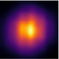
K. ORFANAKIS et al. PHYSICAL REVIEW B 103, 235313 (2021)
(a) 1.0
Patterned
Untrapped
pump M
Trapped
BS BS
RR
time delay
0.5
A B C D
microcavity CCD,
Spectrometer
(b) (c)
0.0
0 300 600 900 1200
FIG. 2. Temporal evolution of |g(1) | for an untrapped P ≈ 1.27Pth
(black circles) and a trapped condensate P ≈ 3.9Pth (orange circles).
10
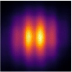
Solid lines are guides for the eye. Inset: Interferograms for four time
delays (150, 250, 340, and 435 ps), denoted A, B, C, and D.
(d)
1.0
coherent state appears in the center of the trap attested by
the presence of interference fringes [Fig. 1(c)]. A line profile
in the center of the interferogram [Fig. 1(d)] can be fit by a
0.5 Gaussian function (the condensate mode profile) multiplied
by a cosine to acquire the fringe contrast [12]. The fringe
contrast is equal to the magnitude of the first-order correlation
function |g(1) (t )|, where t is the time delay. Since the con-
0.0
densate mode is small, spatial dependence in the correlation
-4.0 0.0 4.0 function is negligible. To acquire the temporal dependence of
the correlation function, we record the fringe contrast while
FIG. 1. (a) The interferometer setup, with an adjustable time
changing the time delay. We average over five realizations for
delay. BS, beam splitter; M, mirror; RR, retroreflector. Real-space each time delay.
interferograms (b) below threshold (∼0.75Pth ) and (c) above thresh- The effect of optical confinement on the polariton co-
old (∼2.50Pth ). Pump spots of diameter 2.5 μm are shown by dashed herence is revealed by comparing the decay of temporal
circles. (d) Horizontal line profile across the dotted line of the inter- coherence in the trapped and untrapped condensates (Fig. 2).
ference pattern in (c). The gray line shows the theoretical fit. The latter is characterized by a rapid decay of the correlation
function g(1) (t ) (black curve in Fig. 2) with a decay time (1/e
of fringe contrast) τG ≈ 20 ps (see Fig. 7 in the Appendix).
optically inactive reservoir composed of a hot electron-hole The temporal correlation function of the trapped polariton
plasma and dark excitons that repel and diffuse to the mid- condensate (orange curve in Fig. 2), however, does not exhibit
dle of the trap. During the diffusion, this ’inactive’ reservoir a monotonous decay as previously reported for untrapped con-
relaxes in energy and forms an optically active reservoir of densates [4,6,8,12]. Instead, it exhibits a periodic oscillatory
excitons which couple to cavity photons and form polaritons decay with a period of ∼200 ps. The contrast initially decays
in the middle of the trap. When the polariton density exceeds rapidly to nearly 0 after 150 ps, but then it recovers to 0.35
the condensation threshold, a macroscopically coherent con- after ∼100 ps. We can observe a total of five peaks of g(1) (t )
densate in the ground state of the momentum space (k space) for up to t = 1 ns, approaching the exciton lifetime [30,31].
forms in the center of the trap [28,29] (see the Appendix). The The coherence time for the trapped condensate τph is more
small overlap between the condensate and the hot reservoir at than an order of magnitude longer than that for the untrapped
the pump spots results in a narrower linewidth in optically condensate (see below), which is due to the significant reduc-
confined condensates compared to their unconfined counter- tion of the spatial overlap between the trapped condensate
parts [29]. In the untrapped geometry, the pump consists of and the thermal reservoir of excitons. The insets in Fig. 2
only one spot and the condensate forms on top of the reservoir. illustrate that the interferograms corresponding to the first two
To study temporal coherence, we utilize a Michelson in- minima (A and C) have much lower fringe contrast than those
terferometer in the mirror-retroreflector configuration [see corresponding to the first two maxima (B and D).
Fig. 1(a)]. By varying the position of the moving arm and The period of oscillations and the temporal decay of the
superimposing the image from each arm, we form inter- correlation function depend on the excitation power. Increas-
ferograms for various time delays. Below the condensation ing the pump power from 2.5Pth to 4.3Pth decreases both the
threshold, emission is incoherent and no interference fringes frequency of oscillations and the dephasing rate κ = 1/τph ,
are observed [Fig. 1(b)]. Above threshold, a macroscopically as shown in Fig. 3.
235313-2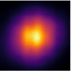
ULTRALONG TEMPORAL COHERENCE IN OPTICALLY …                                                                  PHYSICAL REVIEW B 103, 235313 (2021)

           (a)

                                                                                                                      (b)

                                                                                                                      (c)

     FIG. 3. (a) Temporal decay of fringe contrast for four pumping powers: P = 2.5Pth , 3.2Pth , 3.9Pth , and 4.3Pth . Circles represent experimental
points, while solid lines show the correlation function g(1) (t ) of Eq. (2) as obtained from the numerical simulations of the polariton, Eqs. (3)
and (4), averaged over long integration times. Insets: Power spectrum S(ω) of the polariton field, as obtained via the Fourier transform of
g(1) (t ) obtained from the numerical simulations, illustrating the normal mode splitting by ±J around the central frequency u(n̄1 + n̄2 ). In the
simulations, for each pumping power P we used the phase-coherence time τph = 1/κ shown in (b) and the oscillation period π /J shown in (c).

                            III. THEORY                                           where . . .  denotes the average over time t  . The field E(r, t )
                                                                                  is proportional to the exciton-polariton condensate wave func-
    In Michelson interferometry, the contrast of the real-space
                                                                                  tion. We assume that there are two (nearly) energy-degenerate
interferogram [Fig. 1(d)] is equal to the absolute value of the
                                                                                  modes ψ1 and ψ2 of the polariton condensate with orthog-
first-order field correlation function [12],
                                                                                  onal circular polarizations ε1 and ε2 (ε1 · ε∗2 = 0). The total
                           E ∗ (r, t  )E(r, t + t  )                          field is then E(r, t ) ∝ ε1 ψ1 (t ) + ε2 ψ2 (t ). Substituting this
            g(1) (t ) ≡                                      ,         (1)       into Eq. (1), we have
                         |E(r, t  )|2 |E(r, t + t  )|2

                                                          ψ1 (t + t  )ψ1∗ (t  ) + ψ2 (t + t  )ψ2∗ (t  )
                                      g(1) (t ) =                                                                      .                           (2)
                                                   |ψ1 (t  )|2 + |ψ2 (t  )|2 |ψ1 (t + t  )|2 + |ψ2 (t + t  )|2
   We use the standard approach [32] to describe the two polariton modes via the differential equations
                                  ∂t ψ1 = 21 (R1 N1 − γ1 )ψ1 − i[ 1 (t ) + u11 |ψ1 |2 + u12 |ψ2 |2 ]ψ1 + iJψ2 ,                                    (3a)
                                  ∂t ψ2 = 21 (R2 N2 − γ2 )ψ2 − i[ 2 (t ) + u21 |ψ1 |2 + u22 |ψ2 |2 ]ψ2 + iJ ∗ ψ1 ,                                 (3b)

where R j N j is the pumping rate of the jth polariton from the                   equations and demanding that R j N j − γ j  0 we obtain the
reservoir of N j excitons, γ j is the polariton decay rate, j are                 threshold pumping rate Pj  γ j j /R j for a nonzero polariton
the single-particle energies, ui j are the nonlinear self (i = j)-                intensity |ψ j |2 > 0. Above threshold, neglecting the coupling
and cross (i = j)-interaction rates, and J is the Josephson                       between the two polaritons, the average polariton intensity at
                                                                                                                         P
coupling between the two modes due to the spin-orbit inter-                       steady state is then n̄ j ≡ |ψ j |2  γ jj − R jj , while the exciton
action [20]. The above equations are supplemented by the                                             γj
                                                                                  number is N j      Rj
                                                                                                        .
reservoir equations
                                                                                       We assume that each polariton mode is subject to
                 ∂t N j = Pj −     jNj   − R j N j |ψ j |2 ,            (4)       phase fluctuations with the rate κ = 1/τph , which would
                                                                                  correspond to exponential decay of polariton coherence. We
where Pj is the thermal exciton pumping rate, j is the de-
                                                                                  model these phase fluctuations by a Wiener process: we take
cay (recombination) rate, and R j is the scattering rate of the
                                                                                    j (t ) in Eqs. (3) to be Gaussian stochastic variables with
excitons into the BEC of polaritons. At steady state, ∂t N j = 0
                   P                                                              mean  1,2  = 0 and variance σ 2 = 2κ/δt, where δt is the
we have N j = j +R jj|ψ j |2 . Upon substitution into the polariton

                                                                         235313-3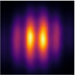
K. ORFANAKIS et al.                                                                        PHYSICAL REVIEW B 103, 235313 (2021)

time increment in the simulations of the system dynamics.                               ACKNOWLEDGMENTS
We simulate the polariton Eqs. (3) numerically, staring with
                                                                        The authors acknowledge fruitful discussions with Anton
small random seed amplitudes ψ1,2 = 0 at some time t0 [33].
                                                                     Nalitov, Alexey Kavokin, Michal Matuszewski, and Jeremy
The initial values of the seed are unimportant, as after a
                                                                     Baumberg. This work was supported by Grant No. EPSRC
short transient, a few tens of picoseconds in duration, the
                                                                     EP/S014403/1. K.O. acknowledges EPSRC for Ph.D. stu-
polariton populations attain close to the steady-state values
                                                                     dentship support through Grant No. EP/L015110/1. P.G.S.
n̄ γP − R determined by the exciton pumping rate (provided
                                                                     acknowledges support from Russian Science Foundation
P  Pth = γ /R). The correlation functions, (2), are then            (Grant No. 19-72-20120), Westlake University (Project No.
obtained upon long-time averaging over the system dynamics.          041020100118), Program No. 2018R01002 supported by
To fit the experimental data in Fig. 3, for each pumping rate Pj     the Leading Innovative and Entrepreneur Team Introduction
we set J /2 and choose an appropriate dephasing rate κ.             Program of Zhejiang, and the bilateral Greece-Russia Polisim-
The periodic oscillations of the field correlation function then     ulator project cofinanced by Greece and the EU Regional
correspond to the beating of the two eigenmodes split by ±J          Development Fund.
and broadened by κ. This is illustrated by the power spectrum
of the polariton field S(ω) given by the Fourier transform of
g(1) (t ) [see insets in Fig. 3(a)]. The spectrum S(ω) is centered            APPENDIX: EXPERIMENTAL METHODS
at frequency u(n̄1 + n̄2 ) and split by ±J.                                                     1. Sample
    The observed energy splitting  2J of the two polariton
                                                                        The sample constitutes a high-Q, 5λ/2, GaAs-based mi-
eigenmodes decreases with an increase in the pumping power
                                                                     crocavity with a top (bottom) DBR mirror comprising 32
and thereby the polariton intensity n̄. Our simulations of the
                                                                     (35) alternating layers of AlAs/Al0.15 Ga0.85 As. Four sets of
Gross-Pitaevskii equations for the polariton BEC indicate that
                                                                     three 10-nm Al0.3 Ga0.7 As/GaAs quantum wells are placed at
with increasing pumping power the lateral size of the polariton
                                                                     the antinodes of the electromagnetic field inside the cavity.
BEC in real space is progressively increased, while its in-
                                                                     Measurements with different detunings are possible due to
plane k-space distribution is correspondingly reduced. This
                                                                     a wedge in the sample thickness which permits continuous
explains the reduction in the Josephson coupling between the
                                                                     tuning of the cavity mode with respect to the exciton mode.
two polariton components due to the spin-orbit interaction
                                                                     Polariton condensation under nonresonant optical pumping in
between the two bare polariton modes [20]. We also note that
                                                                     this sample has been observed previously [24,25].
according to the arguments in [12], the exponential decay of
polariton coherence has the rate κ = 1/τph ∼ γ /2n̄, with γ
being the decay rate of the polariton intensity; hence, the po-                           2. Experimental setup
lariton coherence time is proportional to its intensity, τph ∝ n̄,       The experimental setup is schematically depicted in Fig. 4
and thereby the pumping power (stronger pumping–longer               and consists of four main parts:
coherence time), consistent with our numerical simulations.              i. Laser pattern generation. A tapered amplifier laser sys-
                                                                     tem emitting at 765 nm provides the pump laser beam (red),
                                                                     which is then directed into an AOM for amplitude modulation.
                      IV. CONCLUSIONS                                The final key component is a spatial light modulator (SLM),
                                                                     whose function is generating the optical trapping potentials.
    To summarize, we have demonstrated that optically trap-              ii. Sample imaging and emission collection. A telescope
ping an exciton-polariton condensate increases the coherence         formed by a spherical lens (L4) and a microscope objective
time by more than an order of magnitude compared to that             is then used for scaling the image down to micrometer sizes
of an untrapped condensate. In the untrapped case, the con-          and projecting it onto the microcavity sample mounted inside
densate is formed on top of a sea of hot reservoir excitons          a cryostat. Polariton emission is then collected from the ob-
that directly interacts with the condensate and causes strong        jective in a backscattering geometry and directed towards the
decoherence. In the optically trapped condensate, however,           interferometer. A removable lens (L5) is included for k-space
this hot reservoir is mostly spatially decoupled from the            (momentum-space) measurements.
condensate. This critical difference permits observations of             iii. Phase measurements with an interferometer. Temporal
ultralong coherence times in the trapped condensate. The             coherence measurements are performed by implementing a
highly prolonged coherence of the trapped polariton conden-          Michelson interferometer in the mirror-retroreflector configu-
sate allowed us to observe temporal beating of the first-order       ration. The retroreflector is placed on a linear translation stage
correlation function of the emitted field resulting from the fine    equipped with an integrated electron controller, thus allowing
structure in the condensate energy spectrum. This amounts            the automated movement of the retroreflector.
to a demonstration of measuring the energy splitting of the              iv. Direct and spectral imaging of real and kspace. The last
two interacting polarization modes of the condensate with            part of the setup is for imaging either two-dimensional real
unprecedented precision. Our results can thus be important           space onto a scientific CMOS (sCMOS) camera or k space
for the characterization and control of spinor condensates in        onto the CCD camera of a spectrometer.
lattice potentials for realizing analog and digital polariton
quantum simulators [23,34–37].
                                                                     3. External cavity diode laser and tapered amplifier laser system
   The research data underpinning this publication can be               An integral component of this laser system is the external-
accessed at [38].                                                    cavity diode laser (ECDL) [26,39,40]. In this setup, a laser

                                                               235313-4
ULTRALONG TEMPORAL COHERENCE IN OPTICALLY … PHYSICAL REVIEW B 103, 235313 (2021)
SLM used as output [41]. Optical feedback with a narrow-linewidth
1 M5 laser output is thus established between the end facet of the
M: Mirror
M2
L: Lens laser diode and the diffraction grating, which form an ex-
BB: Beam Blocker
L2
RR: Retroreflector ternal cavity. Moreover, only a narrow range of wavelengths
AOM M4
L3 reflects back to the diode for amplification, because of the
0
BB
wavelength-selective reflectivity of the grating. As the wave-
L1
765 nm 1 1 length is tuned, however, the direction of the output beam
0
M1
BB M3 changes. For this reason, a mirror (M1) is placed on the same
L4
stage as the grating to compensate for grating adjustments.
2 (Removable) M6 3 Besides tunability and narrow linewidth, an ECDL constitutes
k-space lens
a low-cost and compact laser device offering a high stabil-
Cryostat
Objective Lens BS1 L5 BS2
N.A.=0.42 RR
ity [42].
The requirement for single-mode operation requires the
Sample
Flipper mirror
transverse dimension of the laser diode to be of the order
4 CCD
sCMOS M6 of the optical wavelength, which limits the output of the
Spectrometer L6 ECDL (∼100 mW). In our case, this restriction was cir-
M7
cumvented by implementing a tapered amplifier (TA) system
L7
for amplifying the low output of the seed ECDL, while si-
1 Laser pa ern genera on multaneously preserving its spectral properties (wavelength,
2 Sample imaging and emission collec on linewidth etc.) [26,43]. In the TA chip light from the seed
3 Michelson Interferometer is initially inserted from the narrow aperture into a short,
4 Direct and spectral imaging of real and k-space
straight, index-guided section [Figs. 5(b) and 5(c)]. The nar-
row transverse dimension of this region permits the excitation
FIG. 4. Experimental setup for real- and k-space analy- of only the fundamental transverse mode, thus ensuring a high
sis of polariton condensates. The focal length of each lens beam quality. The light radiation is then guided into a longer,
is fL1 = 50 mm, fL2 = 300 mm, fL3 = 400 mm, fL4 = 200 mm, tapered, gain-guided region for optical amplification. This
fL5 (k space) = 300 mm, fL6 = 700 mm, and fL7 = 200 mm. Dis- region is typically made of a III–V semiconductor (AlGaAs in
tances are not drawn to scale. For the AOM and SLM, 0th and 1st our case). While in operation, carrier population inversion is
correspond to the zeroth- and first-order transmission and reflection established through uniform electrical pumping of the tapered
beams, respectively. region. Consequently, optical amplification of the propagating
beam is achieved through the mechanism of stimulated emis-
sion from electron-hole recombination, just as in conventional
diode emitting at 760 nm is initially mounted in a tube lasing. One basic requirement is matching the wavelength of
equipped with an aspheric collimation lens with a focal length the tapered amplifier to the emission of the seed laser, hence
f = 4.51 mm [denoted L1 in Fig. 5(a)]. The external cavity a TA chip with a center wavelength of 765 nm is used for
is built in a modified Littrow configuration in which the colli- amplifying the ECDL. The laser after the TA has a maximum
mated beam is reflected by a grating, with the first diffraction output of ∼2 W.
mode retroreflected back into the diode and the zeroth order The design of the TA chip is such that the propagating
beam is freely diverging in the tapered plane until it is emitted
through the much wider aperture at the end of the tapered
(a)
Laser Output
(b) Seed section [Fig. 5(c)]. An aspheric lens ( f = 4.51 mm) is placed
760 nm
light in
Seed Laser
Diode L4 on either side of the TA chip, the first (L2) for focusing the
input and the other (L3) for collimating the vertical compo-
L1
FI2 Amplified nent of output beam. Apart from high divergence, the output
M1 light out
Diffraction beam is highly astigmatic. Therefore, an additional lens with
Grating
L3 a cylindrical shape (L4) is placed after L3 for collimating the
(c)
Amplified
horizontal component of the beam.
FI1 TA chip Seed
765 nm light in
light out A small portion of the amplified radiation is reflected back
L2
from the front facet of the TA chip, which could disturb the
L: Lens w
M: Mirror
w
single-mode operation of the seed laser. A Faraday isolator
FI: Faraday Isolator M2 M3 d d
is placed between the TA and the ECDL in order to suppress
FIG. 5. (a) The TA laser system. The focal length of the three this backreflected radiation. Furthermore, optical backreflec-
aspheric lenses, L1–L3, is 4.51 mm. For the cylindrical, L4, f = tions can potentially cause permanent damage to TA chips,
50 mm. The diffraction grating is a reflective holographic grating therefore another Faraday isolator (FI2) is placed after the TA
with 1800 grooves/mm. (b) Schematic of the TA chip. (c) Schematic chip to prevent this.
of the top view of the TA chip where the straight, index-guided Finally, for stable operation the temperature is regulated.
section of the chip of length d1 and width w1 and the tapered, Specifically, maintaining the temperature of the seed laser
gain-guided section of length d2 and output width w2 are depicted. diode constant ensures power and frequency stability. Addi-
Typical values are d1 ≈ 0.5 mm, d2 ≈ 1.5–3 mm, w1 ≈ 1–3 μm, and tionally, the TA chip needs to be actively cooled since ∼10 W
w2 ≈ 200 μm [26]. of power is electrically pumped into the chip (I = 3.8 A,
235313-5K. ORFANAKIS et al. PHYSICAL REVIEW B 103, 235313 (2021)
(a) 1st 2nd 3rd (b)
LP branch 30
Coherence time (ps)
(arb. units)
25
Condensate
excited state
20
Condensate 15
ground state
1.0 1.5 2.0
P/Pthd
FIG. 6. (a) Power dependence of the cavity PL emission. Gray
lines serve as a guide for the eye, illustrating where the emission FIG. 7. Power dependence of the coherence time τG for the un-
intensity increases linearly with the pump, while the gray-shaded trapped condensate.
area denotes the nonlinear response of the PL emission associated
with the onset of condensation. (b) Dispersion curve for a pump
power ∼Pth illustrating all light-emitting entities in the microcavity up until ∼2Pth and then is followed by a sublinear third
sample.
regime. An interesting feature is the sublinear behavior of
the third regime, contrary to what has been observed for
V = 2.9 V) but only ∼2 W of optical power is extracted. For untrapped polariton condensates [24].
this purpose, a thermoelectric cooling device is placed below Figure 6(b) shows the E (k ) dispersion curve for a pump
the mounts for both the diode and the TA chip. power near threshold, where k is the in-plane wave vector.
Our laser system provides several advantages over other Most of the emission comes from the condensed polariton
lasers commonly used within the polariton community, e.g., population, which is blueshifted by ∼1.2 meV relative to the
Ti:sapphire [25]. Most importantly, 1ow-intensity noise op- bottom of the LP branch due to polariton self-interactions
eration makes it an ideal laser system for interferometric within the condensate mode and polariton interactions with
measurements. Because random fluctuations in the laser the exciton reservoir [44]. Uncondensed higher-k polaritons
power are minimized, the dephasing induced by our apparatus also contribute to the emission from the cavity. Near threshold
is minimized as well. This in fact has been demonstrated using we can observe the first excited condensate mode at energies
a solid-state laser diode pump [8]. Moreover, the ECDL + TA ∼0.4 meV above the principal one, although much weaker.
laser is a compact device with both a low construction cost We note that the energy splitting between the ground state and
(∼£7500) and low maintenance. However, its tuning range the excited state is two orders of magnitude larger than the
(∼10 nm) is considerably less than that offered by Ti:sapphire energy splitting responsible for our coherence oscillations.
lasers (∼100 nm).
4. Power dependence and k-space emission 5. Untrapped condensate coherence time
The dependence of photoluminescence on pump power The power dependence of the coherence time was also
exhibits three distinct regimes [see Fig. 6(a)]. The low-power measured for untrapped condensates (see Fig. 7). Specifically,
regime corresponds to conventional polariton decay and in- the coherence time is equal to 12 ps just above threshold and
creases linearly with the excitation power. The second regime almost triples for a pumping power ∼2Pth . This coherence
is the onset of condensation at a critical power threshold, Pth . time is more than an order of magnitude smaller than that for
This is accompanied by a nonlinear increase in the emission trapped condensates at all powers.
[1] R. J. Glauber, Phys. Rev. 130, 2529 (1963). [6] R. Balili, V. Hartwell, D. Snoke, L. Pfeiffer, and K. West,
[2] M. R. Andrews, Science 275, 637 (1997). Science 316, 1007 (2007).
[3] M. Köhl, T. W. Hänsch, and T. Esslinger, Phys. Rev. Lett. 87, [7] H. Deng, G. S. Solomon, R. Hey, K. H. Ploog, and Y.
160404 (2001). Yamamoto, Phys. Rev. Lett. 99, 126403 (2007).
[4] J. Kasprzak, M. Richard, S. Kundermann, A. Baas, P. Jeambrun, [8] A. P. D. Love, D. N. Krizhanovskii, D. M. Whittaker, R.
J. M. J. Keeling, F. M. Marchetti, M. H. Szymańska, Bouchekioua, D. Sanvitto, S. A. Rizeiqi, R. Bradley, M. S.
R. André, J. L. Staehli, V. Savona, P. B. Littlewood, Skolnick, P. R. Eastham, R. André, and L. S. Dang, Phys. Rev.
B. Deveaud, and L. S. Dang, Nature (London) 443, 409 Lett. 101, 067404 (2008).
(2006). [9] H. Ohadi, E. Kammann, T. C. H. Liew, K. G. Lagoudakis, A. V.
[5] H. Deng, G. Weihs, C. Santori, J. Bloch, and Y. Yamamoto, Kavokin, and P. G. Lagoudakis, Phys. Rev. Lett. 109, 016404
Science 298, 199 (2002). (2012).
235313-6ULTRALONG TEMPORAL COHERENCE IN OPTICALLY … PHYSICAL REVIEW B 103, 235313 (2021)
[10] A. Trichet, E. Durupt, F. Médard, S. Datta, A. [27] K. G. Lagoudakis, M. Wouters, M. Richard, A. Baas, I.
Minguzzi, and M. Richard, Phys. Rev. B 88, 121407(R) Carusotto, R. André, L. S. Dang, and B. Deveaud-Plédran, Nat.
(2013). Phys. 4, 706 (2008).
[11] J. Fischer, I. G. Savenko, M. D. Fraser, S. Holzinger, S. [28] P. Cristofolini, A. Dreismann, G. Christmann, G. Franchetti,
Brodbeck, M. Kamp, I. A. Shelykh, C. Schneider, and S. N. G. Berloff, P. Tsotsis, Z. Hatzopoulos, P. G. Savvidis, and
Höfling, Phys. Rev. Lett. 113, 203902 (2014). J. J. Baumberg, Phys. Rev. Lett. 110, 186403 (2013).
[12] S. Kim, B. Zhang, Z. Wang, J. Fischer, S. Brodbeck, M. Kamp, [29] A. Askitopoulos, H. Ohadi, A. V. Kavokin, Z. Hatzopoulos,
C. Schneider, S. Höfling, and H. Deng, Phys. Rev. X 6, 011026 P. G. Savvidis, and P. G. Lagoudakis, Phys. Rev. B 88,
(2016). 041308(R) (2013).
[13] E. Rozas, M. D. Martín, C. Tejedor, L. Viía, G. Deligeorgis, [30] C. J. Hwang, Phys. Rev. B 8, 646 (1973).
Z. Hatzopoulos, and P. G. Savvidis, Phys. Rev. B 97, 075442 [31] J. Feldmann, G. Peter, E. O. Göbel, P. Dawson, K. Moore, C.
(2018). Foxon, and R. J. Elliott, Phys. Rev. Lett. 59, 2337 (1987).
[14] E. Rozas, M. D. Martín, C. Tejedor, L. Viía, G. Deligeorgis, [32] M. Wouters, Phys. Rev. B 77, 121302(R) (2008).
Z. Hatzopoulos, and P. G. Savvidis, Phys. Status Solidi B, 256 [33] Simulation parameters are (all in units of 1/ps): γ1,2 = 1, 1,2 =
1800519 (2019). 0.3, R1,2 = 0.001, yielding Pth = γ /R = 300, and thus P =
[15] M. Klaas, H. Flayac, M. Amthor, I. G. Savenko, S. Brodbeck, 2.5Pth , 3.2Pth , 3.9Pth , and, 4.3Pth , leading to n̄1,2 450, 660,
T. Ala-Nissila, S. Klembt, C. Schneider, and S. Höfling, Phys. 870, and 990 after a short transient. We set all the nonlinear
Rev. Lett. 120, 017401 (2018). self- and cross-interaction coefficients the same, ui j ≡ u = 2 ×
[16] J. Klaers, J. Schmitt, T. Damm, F. Vewinger, and M. Weitz, 10−4 , which shifts the mean energy of the polariton condensate
Appl. Phys. B 105, 17 (2011). but does not change the energy difference between the two
[17] J. Marelic, L. F. Zajiczek, H. J. Hesten, K. H. Leung, E. Y X polariton modes. The remaining fitting parameters are J = /2
Ong, F. Mintert, and R. A. Nyman, New J. Phys. 18, 103012 and κ.
(2016). [34] P. G. Lagoudakis and N. G. Berloff, New J. Phys. 19, 125008
[18] J. Schmitt, T. Damm, D. Dung, C. Wahl, F. Vewinger, J. Klaers, (2017).
and M. Weitz, Phys. Rev. Lett. 116, 033604 (2016). [35] N. G. Berloff, M. Silva, K. Kalinin, A. Askitopoulos, J. D.
[19] T. Damm, D. Dung, F. Vewinger, M. Weitz, and J. Schmitt, Nat. Töpfer, P. Cilibrizzi, W. Langbein, and P. G. Lagoudakis, Nat.
Commun. 8, 158 (2017). Mater. 16, 1120 (2017).
[20] E. Kammann, T. C. H. Liew, H. Ohadi, P. Cilibrizzi, P. Tsotsis, [36] K. P. Kalinin and N. G. Berloff, New J. Phys. 20, 113023
Z. Hatzopoulos, P. G. Savvidis, A. V. Kavokin, and P. G. (2018).
Lagoudakis, Phys. Rev. Lett. 109, 036404 (2012). [37] P. A. Kalozoumis, G. M. Nikolopoulos, and D. Petrosyan,
[21] H. Ohadi, A. J. Ramsay, H. Sigurdsson, Y. del Valle-Inclan Europhys. Lett. 129, 37003 (2020).
Redondo, S. I. Tsintzos, Z. Hatzopoulos, T. C. H. Liew, I. A. [38] https://doi.org/10.17630/cb6784fd-521e-46c6-a4fa-
Shelykh, Y. G. Rubo, P. G. Savvidis, and J. J. Baumberg, Phys. c8936cab4f4b.
Rev. Lett. 119, 067401 (2017). [39] A. S. Arnold, J. S. Wilson, and M. G. Boshier, Rev. Sci. Instrum.
[22] H. Ohadi, Y. del Valle-Inclan Redondo, A. J. Ramsay, Z. 69, 1236 (1998).
Hatzopoulos, T. C. H. Liew, P. R. Eastham, P. G. Savvidis, and [40] R. A. Nyman, G. Varoquaux, B. Villier, D. Sacchet, F. Moron,
J. J. Baumberg, Phys. Rev. B 97, 195109 (2018). Y. Le Coq, A. Aspect, and P. Bouyer, Rev. Sci. Instrum. 77,
[23] A. Amo and J. Bloch, C.R. Phys. 17, 934 (2016). 033105 (2006).
[24] P. Tsotsis, P. S. Eldridge, T. Gao, S. I. Tsintzos, Z. Hatzopoulos, [41] P. Maddaloni, M. Bellini, and P. De Natale, Laser-Based Mea-
and P. G. Savvidis, New J. Phys. 14, 023060 (2012). surements for Time and Frequency Domain Applications: A
[25] H. Ohadi, A. Dreismann, Y. G. Rubo, F. Pinsker, Y. del Valle- Handbook. Series in Optics and Optoelectronics (Taylor &
Inclan Redondo, S. I. Tsintzos, Z. Hatzopoulos, P. G. Savvidis, Francis, Boca Raton, FL, 2013).
and J. J. Baumberg, Phys. Rev. X 5, 031002 (2015). [42] F. J. Duarte, Tunable Laser Optics, 2nd ed. (CRC Press, Boca
[26] J. C. B. Kangara, A. J. Hachtel, M. C. Gillette, J. T. Barkeloo, Raton, FL, 2017).
E. R. Clements, S. Bali, B. E. Unks, N. A. Proite, D. D. Yavuz, [43] J. N. Walpole, Opt. Quantum Electron. 28, 623 (1996).
P. J. Martin, J. J. Thorn, and D. A. Steck, Am. J. Phys. 82, 805 [44] D. Bajoni, P. Senellart, E. Wertz, I. Sagnes, A. Miard, A.
(2014). Lemaître, and J. Bloch, Phys. Rev. Lett. 100, 047401 (2008).
235313-7You can also read