SuperCAT4 and T1 transmitter range - User guide Kurzbedienungsanleitung Guide d'utilisation Gebruikershandleiding - Norrscope
←
→
Page content transcription
If your browser does not render page correctly, please read the page content below

SuperCAT 4 and        ®

T1 transmitter range
User guide
Kurzbedienungsanleitung
Guide d’utilisation
Gebruikershandleiding
90/UG110INT/01

ENGLISH           4

DEUTSCH          22

FRANÇAIS         40

NEDERLANDS       58

             3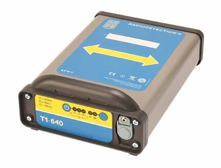
ENGLISH
                                                                          SuperCAT4 range
 ALWAYS DIG WITH CAUTION                                                   Modes / features                   +                  S        CPSS
     Risk of property damage, death, or serious injury may                 StrikeAlert                        ✔                  ✔         ✔
 result if buried pipes and cables are not properly located                Depth                              ✔                  ✔         ✔
 before digging.                                                           Sonde 512 / 640 Hz*                ✔                  ✔
     Read and follow all instructions and warnings in this user            Sonde MF 8 kHz                                        ✔
 guide before using the SuperCAT4+ and T1 transmitter.
                                                                           Sonde HF 33 kHz                    ✔                  ✔
      Regularly check your SuperCAT4+ and T1 transmitter,                  Active Line 512 / 640 Hz*          ✔                            ✔
 in all modes, over a cable which gives a response you are
                                                                           Active Line 8 kHz                  ✔                            ✔
 familiar with.
                                                                           Active Line 33 kHz                 ✔                  ✔         ✔
     Some power cables DO NOT radiate detectable power
                                                                           Active Line 65 kHz                 ✔
 signals.
                                                                           Super HF 131 kHz                   ✔
     Power and Radio signals may not be present. It is
 advisable to use the T1 transmitter whenever searching for                CPS**                                                           ✔
 pipes and cables.                                                         Radio                              ✔                  ✔         ✔

     Do not use the SuperCAT4+ depth estimation function                   Power 50 Hz / 60 Hz*               ✔                  ✔         ✔
 to decide if mechanical digging over a buried conductor is
 appropriate.                                                             *Set by power frequency: 50 / 640 Hz or 60 / 512 Hz
                                                                          **Set by power frequency: 50 / 100 Hz or 60 / 120 Hz
      StrikeAlert ™ may not activate even if a live power cable
 is present.                                                              T1 transmitter range
     The presence of ‘StrikeAlert Activated’ label does not                                             512         640   512/65 640/65     131
 guarantee that this feature is activated.
                                                                           Induction 8 kHz               ✔          ✔        ✔       ✔         ✔
    Keep mobile phones away from cable and pipe locators
                                                                           Induction 33 kHz              ✔          ✔                          ✔
 when in operation. Minimum distance 60cm/24" recommended.
                                                                           Induction 65 kHz                                  ✔       ✔
     The SuperCAT4+ cannot indicate whether a signal comes
                                                                           Direct Connect 512 Hz         ✔                   ✔
 from a single conductor or from several cables or pipes
 bundled or buried in close proximity to each other.                       Direct Connect 640 Hz                    ✔                ✔
                                                                           Direct Connect 8 kHz          ✔          ✔        ✔       ✔         ✔
      It is recommended that the SuperCAT4+ and T1
 transmitter are serviced at least once a year and have their              Direct Connect 33 kHz         ✔          ✔                          ✔
 calibration validated using Radiodetection approved test                  Direct Connect 65 kHz                             ✔       ✔
 equipment. Radiodetection will accept no responsibility for
                                                                           Direct Connect 131 kHz                                              ✔
 repairs carried out by unauthorized repairers.
     Even if using a SuperCAT4+ and T1 transmitter, ALWAYS
 DIG WITH CAUTION.

Call your local support number (available from: www.radiodetection.com)
for questions regarding the proper use, maintenance, and repair of the
SuperCAT4+ and T1 transmitter.

                                   4                                                                            5
ENGLISH
SuperCAT4+ user guide                                                                                                   Using the locator
This user guide covers all models of the                                           1                        2   3       Grip the locator’s handle. Press and hold the trigger and listen for the
SuperCAT4+ locator range.                                                                                               bleep indicating the batteries are OK. Replace both batteries if there
                                                                                                                        is no bleep or if the battery icon is flashing.
Locator functions                           5                                                                       4
                                                                                                                        When required, use the frequency selection button to cycle between
1.   On/Off Trigger.                                                                                                    operating frequencies.
     Press and hold to use the locator.
                                                                                                                        Hold the locator with the blade vertical and with the lower edge just
2.   LCD Screen with automatic depth                                                                                    above the ground. Do not swing it or tilt it more than a few degrees
     readout and frequency selection button.                                                                            from the vertical.

3.   Loudspeaker.                                                                                                       Swinging the locator will affect locate accuracy.
     Detachable speaker for use in
     noisy environments.                                                                                            6   Depth Measurement
4.   Sensitivity Control.                                ALK/NiMH
                                                                                                                        The locator will automatically measure and display the depth in Active
                                                                                                                        Line, sonde and CPS modes.
5.   Mode Selector Switch.

6.   Battery compartment.                                                                                               Note: The locator does not measure depth in Power or Radio
                                                                                                                        modes.
                                                         Patent information:
                                                         www.radiodetection.com/patents
                                                         © 2017 Radiodetection Ltd.

                                                                                          01/CH3418L13/01

                                                                                                                        Method: Locate the utility as follows. Hold the locator still and
Screen features                                                                                                         vertically centered above the detected line and across the line of the
The locator’s screen displays the following features:                                                                   pipe/cable.

                                                                                                                        Note: A depth measurement will not be displayed where
                                                                                                                        environmental conditions are poor (e.g. weak signal or interference).
Depth / Warning readout                                 Mode /StrikeAlert
                                                                                                                        The measurement is to the center of the pipe/conductor or to the
                                                                     Signal Strength
                                                                                                                        center of the sonde, which may rest at the bottom of the pipe.
                                                                           bargraph
Mode                                                                                                                    Do not use the depth measurement function to decide if mechanical
L = Active line                                     Frequency selection                                                 digging is appropriate.
R = Radio
P = Power                                                                                                               Dynamic Overload Protection
S = Sonde                                                                                                               All SuperCAT4+ locators incorporate Dynamic Overload Protection,
or                                                                                                                      a powerful signal processing tool that identifies and automatically
C = CPS (CPS model)                                                                                                     rejects electrical interference that may otherwise overload the locator’s
                                                                                                                        electronics. Dynamic Overload Protection allows the operator to
Speaker                                                                                                                 locate pipes and cables in electrically noisy environments such as near
                                                                                                                        power sub stations or near overhead high-voltage cables. Note that
When using the locator in noisy environments, the speaker
                                                                                                                        Dynamic Overload Protection will not overcome very high levels of
can be detached and held closer to the ear.
                                                   91dB(A)                                                              interference. In this situation the Signal Overload Warning will appear
     To avoid excessive noise exposure,                                                                                 (see Warnings).
hold the speaker no closer than 15cm
(6") from the ear. Prolonged use in this
position should be avoided.                             15cm

                                     6                                                                                                                      7
ENGLISH
Power and Radio mode location T1 – 1W transmitter
Note: After completing a power mode sweep we recommend that
The T1 is a general purpose, 1 Watt, transmitter that provides three
you repeat the procedure in radio mode; the procedure is the same.
locatable frequencies, two induction frequencies and two power
levels. By default, the T1 induces a signal directly into the ground.
Power mode
It is the perfect companion to the SuperCAT4+ range of cable and
Power mode detects power signals radiated by loaded power cables. pipe locators.
To select Power mode, rotate the function switch until the LCD displays 1 2 4 5
a P icon. Rotate the sensitivity control fully clockwise for maximum Transmitter features
sensitivity but reduce if there is a blanket signal across the site. Define
1. On/Off/Frequency Selector.
the excavation site and carry out a grid pattern sweep. Note that
LEDs indicate which frequency
sometimes the signal may be re-radiated from other conductors.
has been selected.
Sweep the site holding the SuperCAT4+ upright at your side. a. First press switches the
Continue the sweep beyond the perimeter of the site. The presence of transmitter on and selects
a buried conducting pipe or cable will be indicated by a tone emitted the lowest locate frequency
from the loudspeaker and a kick on the LCD’s bar graph. – depending on product
Keep the SuperCAT4+ blade vertical and move slowly backwards and specified. See T1 transmitter
range table. 3
forwards over the conductor. Reduce the sensitivity for a narrower
response; this will allow you to pinpoint the conductor. With the NOTE: the lowest frequency is only available for direct connections
SuperCAT4+ use the meter deflection to aid pinpointing. Maximum and will not work in induction mode.
meter deflection and audible volume from the speaker will indicate the b. Second and third presses select the mid and highest frequencies.
position of the conductor.
c. Fourth press turns the transmitter off.
When directly over the conductor and with the sensitivity level set for
2. Power Selector
a narrow response, rotate the SuperCAT4+ on its axis until the signal
minimum is found. The blade is now parallel with the conductor. Selects either high or low power level. LEDs indicate which
power level is active.
Trace the conductor beyond the site and mark the position as required.
3. Accessory Socket
Connects cables or optional accessories such as the Signal
Radio Mode
Clamp, Direct connection lead or Live Plug Connector.
Radio mode detects broadcast signals that originate from radio When connected, induction mode is disabled. A loudspeaker
transmitters. These signals penetrate the ground and are re-radiated emits a pulsing tone to indicate sufficient battery charge and
by buried conductors. However, depending on your location, these a satisfactory direct connection.
signals may not be present. 4. Battery Access Panel. When no tone is audible the batteries
must be replaced.
StrikeAlert™ 5. Arrows
The StrikeAlert feature warns the operator of shallow pipes and The arrows on the top panel label indicate the required transmitter
cables. alignment above the pipe or cable when using Induction mode.
The arrows and the pipe or cable must be parallel. Alignment is
When a shallow cable or pipe is detected in Power or Active line Mode, not required when the T1 is in Active mode.
StrikeAlert flashes an asterix and sounds a distinctive warbling audio
tone. StrikeAlert is not activated when tracing sondes or Radio signals. Note: Turn off the T1 and remove any cables or accessories
before changing batteries.
8 9ENGLISH
Direct connection
Cable location using the
Connection to a power cable sheath should only be
T1 transmitter undertaken by qualified personnel.
The T1 transmitter is used to actively apply a locate signal to cables Direct Connection is an effective way to apply the T1 locate signal to
or metallic pipes. This signal can be traced using the locator in Active a specific cable or pipe network so that it can be traced from above
Line mode (L). ground. Connections can be made to any metallic part of the pipe or
Use of the T1 is strongly recommended, as passive, power or radio cable such as valves, meters, junction boxes, street lights, pipeline
signals may not be present, or detectable, on all cables and pipes. markers or other access points.
Procedure
With the T1 switched off, plug the Direct Connect lead into the
accessory socket. Attach the red lead to the pipe or cable (if necessary,
clean the connection point to ensure a good electrical contact). If the
jaws of the clip do not open far enough, and if the connection point is a
suitable material, use the supplied magnet.
Connect the black lead to the earth stake which should be secured in
the ground 3 – 4m away from, and at right angles to the target line.
Alternatively the black lead may be clipped to a valve box, manhole
cover or another earthed point. Use the earth spool lead to extend the
earth connection if necessary.
Induction mode
Switch the T1 on. A good connection is indicated by a drop in
The T1 has an internal aerial that will induce a signal onto a line (or lines) loudspeaker tone. If there is no tone replace the batteries.
directly below it. This is useful when you do not have direct access to
Start with the T1’s lowest power setting. A pulsed loudspeaker tone
the line. Generally, induction is only effective to depths of 2m (6’6”).
indicates a good connection. If there is no tonal change, check the
Note that the induction mode is indiscriminate and will apply a signal to
electrical contacts and the ground. If necessary, change the position of
all conductors within its range. the ground stake or pour water over the ground contact if placed in dry
Induction is only available with frequencies 8kHz and above. soil or sand. If there is still no change in tone increase the power setting.
Note: The locator can detect a signal many times weaker than
Procedure
what is necessary for a T1 tone change and short distances can
Place the transmitter over the approximate position of the underground be traced without a pulsed tone from the loudspeaker.
utility with arrows pointing parallel to its path. Set the locator’s sensitivity
To remove the direct connection cable grip the black sleeve on the
to 100% and start locating the line at least 10m (33 feet) away from the
outside of the plug and ease off the connector.
transmitter. Mark the ground when the locator detects any signal spike.
Do not pull the wire as this may damage the cable and/or
Note: Induction cannot apply a signal to a line below reinforced
concrete. socket.
Note: The locator may detect the transmitter signal directly Regularly check your locator and T1, in all modes over a cable which
from the T1 rather than the target line, so do not attempt depth provides a response that you are familiar with.
measurements within 10 meters of the transmitter.
To check if you are detecting a signal from the T1, point the locator directly
at the transmitter. If the locator’s signal strength increases, either reduce the
transmitter power or increase the distance between you and the transmitter.
If the signal strength decreases, the signal is from the buried line.
10 11ENGLISH
Signal Clamp (optional extra)
The optional Signal Clamps can be used to apply a
T1 locate signal safely to a cable or pipe up to
215mm (8.5”) in diameter without interrupting
the supply. Signal clamps are not suitable for connecting
around lamp posts.
Procedure
With the T1 switched off, plug the Clamp lead into the accessory
socket. Place the Clamp around the pipe or cable ensuring the jaws
are completely closed.
Switch the T1 on, then open and close the Clamp. If the jaws are A sonde radiates a peak field from the center of its axis with ghost signals
closing correctly there will be a change in tone as the jaws are closed. at each side of the peak. Move the locator to one side and then along the
axis of the sonde forwards and backwards to detect the ghost signals.
An earth connection from the T1 is not necessary but optimal signal
transfer is only generally achieved if the target line is grounded at both Radiodetection recommends locating the ghost signals as finding
ends. This is usually the case with power cables. them confirms the position of the main peak. To lose the ghost signals,
reduce the sensitivity of the locator; this should leave only the main
WARNING! To avoid the risk of electric shock, the signal peak signal detectable.
clamp must be connected to the transmitter before being placed
around the pipe or cable. With the locator sensitivity set as desired,
propel the sonde along 1m (3-4 feet) and
stop. Place the locator over the estimated
Locating a sonde position of the sonde and:
The SuperCAT4+ locators are capable of locating a Radiodetection 1. Move the locator backwards and
sonde. Before attempting to locate a sonde ensure that the sonde’s forwards with the blade’s orientation
batteries are fully charged. Radiodetection recommends using new or parallel to the sonde.
fully recharged batteries at the beginning of each day and preferably 2. Stop when the bar graph indicates a
at the start of each job. Also check that the locator is operating at the clear peak.
same frequency as the sonde and that they are both working correctly.
3. Rotate the locator as if the blade were a
To test the locator and the sonde, position the sonde at a distance pivot, stop when the display indicates a
equal to its rated depth range from the locator. Point the locator at the clear peak response.
sonde with its blade parallel to the direction the sonde is travelling.
4. Move the locator from side to side until
Check that the bar graph shows more than 50% at high sensitivity
the bar graph indicates a clear peak.
Note: The blade of the locator must be in line with the sonde; this 5. When the locator locates a peak signal,
is the opposite to Active line locate method. it will automatically calculate the depth
Procedure of the sonde. Observe the depth reading
while moving the locator from side to
1. Attach the sonde to the rod and insert it into the drain or duct to
side; the lowest reading will be the
be mapped. Keep the sonde just in view.
correct location.
2. Hold the locator vertically directly over the sonde with the blade in
line with the sonde’s orientation. Repeat each step in smaller increments with the locator blade resting
3. Adjust the sensitivity of the locator to give a bargraph reading on or near the ground. The locator should now be directly above the
between 60-80%. sonde with the blade parallel with the sonde; mark this position.
12 13ENGLISH
Propel the sonde a further 1m (3-4 feet) along the pipe and pinpoint b. Increase the sensitivity slightly to find the ghost signal.
and mark. Repeat the procedure along the route at similar intervals. Note that between the main peak and ghost there is a Null
Note, while tracking the sonde altering the locator’s sensitivity is not or minimum.
required unless the depth of the pipe, or the distance between locator 2. Mark the Null or minimum position for reference.
and sonde changes.
3. Now move behind the sonde and repeat step 1.
Measuring sonde depth 4. Find the Null between the ghost and main peak. See points A and
B on the diagram.
Pinpoint the sonde as previously described. Then rest the locator on
the ground with the blade’s orientation parallel to the orientation of the 5. The higher the sensitivity of the locator the sharper the Null’s
sonde. Adjust the sensitivity to give a meter reading of 60% to 80% appear.
on the LCD’s bargraph. 6. Measure the distance between points A and B and multiply by 0.7
Note that the depth reading is the distance from the bottom of the to give an approximate depth measurement.
locator blade to the center of the sonde and not to the drain or duct
being located. Warnings
CAUTION: Ensure Depth readings are taken from peak readings. Signal Overload
Depth readings taken from ghost signal position will be incorrect. If the locator is used in areas where very large power signals are
present, the signal bargraph will flash. In this condition the sensitivity
Depth measurement is automatic. Depth reading will be displayed
control and depth function will not operate and you are advised to try
when the locator is moved slowly across the sonde. The shallowest
lifting the locator to bring it out of the overloaded condition or use in a
depth reading displayed on the LCD is also the correct position
different location.
directly above the sonde.
Deactivating
If required the StrikeAlert warnings can be temporarily disabled by
pressing and holding the frequency selection button for the duration
of the battery test bleep at switch on.
Live Plug Connector
Do not use the supplied Direct Connect
leads to connect to live cables. Use the
Radiodetection Live Plug Connector or Live
Cable Connector. Failure to do so may result
in injury or equipment damage.
Connection to live power cables
should only be undertaken by
If the signal is too weak or unstable the locator unit will not calculate qualified personnel.
depth. In this case use a more powerful sonde or use the Pinpoint
procedure described below.
Pinpoint Procedure. The optional Live Plug Connector applies the transmitter signal to a
live domestic power socket and via the domestic wiring system on the
1. Move the locator ahead of the sonde.
service cable and the supply cable in the street. The signal should be
a. Ensure the blade’s orientation is parallel with the sonde’s detectable on the supply system to a few hundred meters each side of
orientation the point of application.
14 15ENGLISH
Note: Do not connect the transmitter to live cables without using
a Live Plug Connector or Live Cable Connector.
Service and Maintenance
Procedure SuperCAT4+ and the T1 transmitter are designed to require
With the T1 switched off, connect the Live Plug Connector to the minimal recalibration. However, as with all safety equipment, it is
transmitter and then to the live domestic power socket. Where recommended that they are serviced and have their calibration
required switch on the power socket. validated at least once a year using Radiodetection approved test
equipment. Radiodetection accepts no responsibility for service,
Note: The Live Plug Connector provides protection to 250V AC. calibration or repairs carried out by non-authorised persons.
Sweep the site holding the locator upright at your side. Continue To check when the SuperCAT4+ is next due to be calibrated, squeeze
the sweep beyond the perimeter of the site. The presence of a the trigger, then press the depth button until ‘C’ (Configuration) is
buried conducting cable will be indicated by a tone emitted from the displayed. The display will now automatically step through the following
loudspeaker and a spike on the LCD’s bar graph. information: ‘S’ (software version), ‘D’ (day), ‘M’ (month) and ‘Y’ (year).
Keep the locator’s blade vertical and move slowly backwards and
forwards over the conductor. Reduce the sensitivity for a narrower Functional test
response; this will allow you to pinpoint the conductor. With the Radiodetection recommends that you perform a daily functional test
locator use the meter deflection to aid pinpointing. Maximum meter on your locator and transmitter before use.
deflection and audible volume from the speaker will indicate the • Place the T1 on the ground, switch on and check for an audible
position of the conductor. sound. If no sound is heard, replace the batteries before use.
When directly over the conductor and with the sensitivity level set for a • Switch on the locator by squeezing the trigger, checking for an
narrow response, rotate the locator on its axis until the signal minimum initial ‘chirp.’ A low tone indicates low batteries. If no sound is
is found. The blade is now parallel with the conductor. heard, replace the batteries before use.
Trace the conductor beyond the site and mark the position as required. • Rotate the locator function switch and check that the appropriate
letter is displayed in each position of the switch.
FlexiTrace™ – to locate non-metallic utilities
• Set the locator and transmitter to the same active frequency.
FlexiTrace is a 50m (164’) or 80m (260’) flexible conductive rod with With the locator in Active Line mode (L), set the sensitivity at its
a built-in sonde that can be inserted into non-metallic pipes and ducts maximum gain, hold at waist height pointing toward the T1 with the
to allow them to be located at depths of up to 3m (10’) FlexiTrace flattest part of the housing parallel to the ground and check that
can be inserted into a pipe or duct as small as 12mm (½”) internal the SuperCAT4+ can detect the T1 up to 15m away with a clearly
diameter, and with bends as tight as 250mm. audible sound.
To use as a mouse, connect both transmitter
leads to the FlexiTrace lugs. In this mode,
only the tip of the FlexiTrace will be locatable.
To trace the whole length, connect the red
transmitter lead to a FlexiTrace terminal and
ground the black lead, either to the earth stake
or to an appropriate earthing point.
16 17ENGLISH
Replacing batteries Product specification
Do not mix new and old batteries or different types of
batteries, as this may cause them to overheat. Locator Technical Specification
SuperCAT4+ Locate Frequency Sensitivity Depth Depth
performance range @ 1m Good Poor
To replace batteries, open the access cover using conditions conditions
a screwdriver or coin. Use two LR20 (D-cell) Power signals 50 Hz – 1.5 kHz 3 mA 3m 2m
alkaline batteries or equivalent NiMH rechargeable (P)
batteries. Radio signals 15 kHz – 30 kHz 25 μA 2m 1m
(R)
T1
T1 signals (L)1 512/640 Hz 500 μA 4m 2m
To replace batteries, Unscrew fastener on the rear 8 kHz 100 μA
33 kHz 5 μA
panel and replace with four LR20 (D cells) alkaline
65 kHz 5 μA
batteries. Observe correct battery polarity as indicated 131 kHz 5 μA
on the top-panel label.
Sonde (S) 1 512 Hz / 640 Hz / N/A Up to 15 m
8 kHz / 33 kHz
1
Model dependent
Dynamic range 120 dB @ 10 Hz
Dynamic Overload Protection 40 dB @ 50 Hz (automatic)
Locate accuracy ± 10% of depth
Depth accuracy (on undistorted Line: 5% 0.1 m to 3 m (4 in to 10 ft)
signal and with no adjacent Sonde: 5% 0.1 m to 7 m (4 in to 16 ft)
signals)
Operating temperature range -20°C to +50°C (4°F to 122°F)
Storage temperature range -20°C to 70°C (4°F to 158°F)
Environmental protection IP54
Batteries Locator:
2 x Alkaline or NiMH D-cells (LR20)
Transmitter T1:
4 x Alkaline D-cells (LR20)
Data interface USB 2.0 – for future use
Recommended service interval 1 year
Warranty 12 months from purchase
Unit Weight Locator:
2.3 kg (5.1 lbs) (including batteries)
Transmitter:
1.7 kg (3,8 lbs) (including batteries)
18 19ENGLISH
Warranty c. Damage or defects caused by use, operation or treatment of the
Subject to the conditions set out herein, Radiodetection Limited product inconsistent with its intended use.
expressly and exclusively provides the following warranty to original end d. Damage or changes to the product as a result of:
user buyers of Radiodetection products. i. Misuse, including: - treatment resulting in physical, cosmetic or
surface damage or changes to the product or damage to liquid
Radiodetection hereby warrants that its products shall be free from
crystal displays.
defects in material and workmanship for one year starting from point
ii. Failure to install or use the product for its normal purpose or
of sale to end customer. Extensions of this warranty period may be
in accordance with Radiodetection instructions on installation
available where the same terms and conditions apply.
or use.
Statement of warranty conditions iii. Failure to maintain the product in accordance with
Radiodetection instructions on proper maintenance.
The sole and exclusive warranty for any Radiodetection product found
to be defective is repair or replacement of the defective product iv. Installation or use of the product in a manner inconsistent with
at Radiodetection’s sole discretion. Repaired parts or replacement the technical or safety laws or standards in the country where
it is installed or used.
products will be provided by Radiodetection on an exchange basis and
will be either new or refurbished to be functionally equivalent to new. v. Virus infections or use of the product with software not
provided with the product or incorrectly installed software.
In the event this exclusive remedy is deemed to have failed of its
vi. The condition of or defects in systems with which the product
essential purpose, Radiodetection’s liability shall not exceed the
is used or incorporated except other ‘Radiodetection products’
purchase price of the Radiodetection product. In no event will
designed to be used with the product.
Radiodetection be liable for any direct, indirect, special, incidental,
vii. Use of the product with accessories, peripheral equipment and
consequential or punitive damages (including lost profit) whether
other products of a type, condition and standard other than
based on warranty, contract, tort or any other legal theory.
prescribed by Radiodetection.
Warranty services will be provided only with the original invoice viii. Repair or attempted repair by persons who are not
or sales receipt (indicating the date of purchase, model name and Radiodetection warranted and certified repair houses.
dealer’s name) within the warranty period. This warranty covers only ix. Adjustments or adaptations without Radiodetection’s prior
the hardware components of the Radiodetection product. written consent, including:
Before a unit is submitted for service or repair, under the terms of i. upgrading the product beyond specifications or features
this warranty or otherwise, any data stored on the unit should be described in the instruction manual, or modifications to
backed-up to avoid any risk of data loss. Radiodetection will not be the product to conform it to national or local technical or
responsible for loss or erasure of data storage media or accessories. safety standards in countries other than those for which
the product was specifically designed and manufactured.
Radiodetection is not responsible for transportation costs and risks
associated with transportation of the product. The existence of a x. Neglect e.g. opening of cases where there are no user
defect shall be determined by Radiodetection in accordance with replaceable parts.
procedures established by Radiodetection. xi. Accidents, fire, liquids, chemicals, other substances, flooding,
vibrations, excessive heat, improper ventilation, power
This warranty is in lieu of any other warranty, express or implied,
surges, excess or incorrect supply or input voltage, radiation,
including any implied warranty of merchantability or fitness for a electrostatic discharges including lightning, other external
particular purpose. forces and impacts.
This warranty does not cover:
Copyright © 2017 Radiodetection Ltd. All rights reserved. Radiodetection is a subsidiary of SPX
a. Periodic maintenance and repair or parts replacement due to wear Corporation. Radiodetection, SuperCAT, SuperCAT4+, StrikeAlert, eCert are trademarks of
and tear. Radiodetection in the United Kingdom and/or other countries. The Bluetooth word, mark and logos
are registered trademarks of Bluetooth SIG, Inc. and any use of such trademarks by Radiodetection
b. Consumables (components that are expected to require periodic is under license. Due to a policy of continued development, we reserve the right to alter or amend
replacement during the lifetime of a product such as non any published specification without notice. This document may not be
copied, reproduced, transmitted, modified or used, in whole or in part,
rechargeable batteries, bulbs, etc.). without the prior written consent of Radiodetection Ltd.
sales@norrscope.comSuperCAT4-Baureihe
GRABEN SIE IMMER MIT VORSICHT Betriebsarten / Funktionen + S CPSS
Gefahr von Sachschäden, Tod oder schweren Verletzungen besteht, StrikeAlert ✔ ✔ ✔
wenn erdverlegte Rohre und Kabel nicht vor Beginn einer Ausschachtung Tiefe ✔ ✔ ✔
gründlich geortet werden. Sonde 512/640 Hz* ✔ ✔
DEUTSCH
Lesen Sie alle Anweisungen und Warnungen in dieser Sonde MF 8 kHz ✔
Bedienungsanleitung, bevor Sie den SuperCAT4+ und den T1-Sender
Sonde HF 33 kHz ✔ ✔
verwenden.
Aktive Leitung 512 / 640 Hz* ✔ ✔
Kontrollieren Sie Ihre SuperCAT4- und T1-Sender regelmäßig in allen
Aktive Leitung 8 kHz ✔ ✔
Betriebsarten über einem Kabel, das Ihnen bekannte Rückmeldungen zeigt.
Aktive Leitung 33 kHz ✔ ✔ ✔
Einige Stromnetz-Kabel geben KEINE erkennbaren STROMSIGNALE ab.
Aktive Leitung 65 kHz ✔
Möglicherweise sind keine Strom- und Radiosignale vorhanden. Super HF 131 kHz ✔
Es ist ratsam, bei der Suche nach Rohrleitungen und Kabeln immer den
T1-Sender einzusetzen. CPS** ✔
Radio ✔ ✔ ✔
Verwenden Sie die Tiefen-Anzeige am SuperCAT4+ nicht zur
Beurteilung, ob maschinelle Ausschachtungen über einem erdverlegten Stromnetz 50 Hz/60 Hz* ✔ ✔ ✔
Leiter zulässig sind.
*Eingestellt durch folgende Netzfrequenz: 50 / 640 Hz oder 60 / 512 Hz
Die Funktion StrikeAlert™ schlägt u. U. auf spannungsführende **Eingestellt durch folgende Netzfrequenz: 50 / 100 Hz oder 60 / 120 Hz
Stromnetz-Kabel nicht an.
Der Aufkleber „StrikeAlert aktiviert“ ist keine Garantie dafür, dass T1-Sender-Baureihe
diese Funktion auch wirklich aktiviert ist. 512 640 512/65 640/65 131
Verwenden Sie keine Mobiltelefone in direkter Nähe von Induktion 8 kHz ✔ ✔ ✔ ✔ ✔
Kabel- und Leitungsortungsgeräten, wenn diese Geräte im Einsatz sind.
Induktion 33 kHz ✔ ✔ ✔
Mindestabstand von 60cm/24Zoll empfohlen.
Induktion 65 kHz ✔ ✔
Der SuperCAT+ kann nicht anzeigen, ob ein Signal von einem
Direktanschluss 512 Hz ✔ ✔
einzelnen Leiter oder von mehreren gebündelten oder dicht beieinander
verlegten Kabeln oder Rohrleitungen kommt. Direktanschluss 640 Hz ✔ ✔
Direktanschluss 8 Hz ✔ ✔ ✔ ✔ ✔
Es wird empfohlen, dass SuperCAT4+ und T1-Sender mindestens
einmal jährlich gewartet werden und die Kalibrierung mit Radiodetection- Direktanschluss 33 Hz ✔ ✔ ✔
zugelassenen Prüfmitteln zu bestätigen. Radiodetection übernimmt keine Direktanschluss 65 Hz ✔ ✔
Verantwortung für Reparaturen, die von nicht autorisierten Betrieben Direktanschluss 131Hz ✔
durchgeführt wurden.
Auch unter Verwendung eines SuperCAT4+ und eines T1-Senders gilt:
BEI AUSSCHACHTUNGEN STETS VORSICHTIG SEIN.
Rufen Sie bei Fragen zur richtigen Anwendung, Wartung und Reparatur von
SuperCAT4+ und T1-Sender Ihre örtliche RD-Niederlassung an (erreichbar:
www.radiodetection.com).
22 23Bedienungsanleitung SuperCAT4+ Einsatz des Empfängers
Diese Bedienungsanleitung deckt sämtliche Modelle der 1 2 3 Halten Sie den Empfänger am Griff. Halten Sie den Auslöser gedrückt und beachten
Empfängerreihe SuperCAT4+ ab. Sie den Piepton, der den Batteriezustand anzeigt. Ist kein Piepton zu hören oder blinkt
das Batteriesymbol, müssen beide Batterien ersetzt werden.
Ortungsfunktionen 5 4
Bei Bedarf drücken Sie die Frequenzauswahltaste, um durch die Betriebsfrequenzen
DEUTSCH
1. Ein-/Aus-Trigger. zu schalten.
Drücken und Halten zum Gebrauch des Empfängers.
Halten Sie den Empfänger mit vertikal hängendem Blatt knapp über dem Boden.
2. LCD-Schirm mit automatischer Tiefenablesung Schwingen Sie das Gerät nicht hin und her und kippen Sie es nicht weit aus der
und Frequenzauswahltaste. Vertikalen.
3. Lautsprecher. Hin- und Herpendeln des Empfängers wirkt sich negativ auf die Ortungsgenauigkeit
Abnehmbarer Lautsprecher für den aus.
Einsatz in lauten Umgebungen. 6
Tiefenmessung
4. Empfindlichkeitsregler. ALK/NiMH
Der Empfänger misst und zeigt die Tiefe automatisch in den Betriebsarten Aktive
5. Moduswahlschalter.
Leitung, Sonde und CPS (KKS) an.
6. Batteriefach.
HINWEIS: Der Empfänger misst keine Tiefe in den passiven Modi Strom und
Patent information:
www.radiodetection.com/patents
© 2017 Radiodetection Ltd.
01/CH3418L13/01
Radio.
Anzeigen auf dem Bildschirm Methode: Orten der Einrichtung wie folgt: Halten Sie den Empfänger ruhig und
Auf dem Bildschirm des Empfängers wird Folgendes angezeigt: vertikal mittig über der georteten Einrichtung, das Blatt quer (90°) zum Verlauf.
Hinweis: Bei ungünstiger Umgebung (z. B. schwaches Signal oder Störfelder)
wird keine Tiefe angezeigt.
Tiefen- / Warnungsanzeigen Modus / StrikeAlert
Die Tiefenmessung erfolgt auf die Mitte der besendeten Einrichtung oder der Sonde,
Signalstärke-
die auf dem Boden der Einrichtung ruhen sollte.
Balkenanzeige
Modus Verwenden Sie die Funktion Tiefenmessung nicht zur Entscheidung, ob maschinelle
L = Aktive Leitung Frequenzauswahl Ausschachtung zulässig ist.
R = Radio
P = Stromnetz (Power) Dynamischer Überlastungsschutz
S = Sonde Alle Ortungsempfänger der Reihe SuperCAT4+ sind mit dynamischem
oder Überlastungsschutz ausgerüstet. Hierbei handelt es sich um eine leistungsfähige
C= CPS (KKS-Modell) Funktion zur Signalverarbeitung, die elektromagnetische Störungen erkennt und
eliminiert, welche die Elektronik des Empfängers überlasten könnten. Mit dem
Lautsprecher dynamischen Überlastungsschutz können Rohrleitungen oder Kabel in Umgebungen
mit elektromagnetischen Störfeldern, wie in der Nähe von Umspannwerken oder
Wird der Empfänger in lauter Umgebung eingesetzt, kann der Lautsprecher
unter Hochspannungsleitungen, geortet werden. Beachten Sie, dass der dynamische
abgenommen und ans Ohr gehalten werden.
91dB(A) Überlastungsschutz sehr hohe Interferenzpegel nicht bewältigen kann. In einer
Halten Sie den Lautsprecher nicht näher solchen Situation wird die Signalüberlast-Warnung ausgelöst (siehe Warnungen).
als 15 cm (6 Zoll) an Ihr Ohr, um übermäßigen
Lärmeinfluss zu vermeiden. Ein längerer
Einsatz in dieser Position ist zu vermeiden. 15cm
24 25Ortung in passiven Modi Strom und Radio T1 – 1W-Signalsender
Hinweis: Nach dem Absuchen im Strom-Modus empfehlen wir erneutes
Der T1 ist ein universeller 1-Watt-Signalsender, der drei ortbare Frequenzen, zwei
Absuchen im Radio-Modus; das Verfahren ist dasselbe.
Induktions-Frequenzen und zwei Leistungsstufen vorhält. Standardmäßig induziert der
T1 sein Signal direkt in den Boden.
Strom-Modus:
Er ist der perfekte Begleiter der Kabel- und Rohrleitungs-Ortungsempfänger der
Der Strom-Modus erkennt Strom-Signale, die belastete Stromnetz-Kabel abstrahlen. Reihe SuperCAT4+.
DEUTSCH
Drehen Sie zur Auswahl den Funktions-Wahlschalter, bis der LCD ein P-Symbol 1 2 4 5
(Power) anzeigt. Drehen Sie den Empfindlichkeitsregler im Uhrzeigersinn bis Merkmale des Senders
zum Anschlag, um die maximale Empfindlichkeit einzustellen. Reduzieren Sie die
1. Ein-/Aus-/Frequenz-Wahlschalter.
Empfindlichkeit, wenn im Ausschacht-Bereich durchgehend Signal angezeigt wird.
LEDs zeigen die
Definieren Sie den Ausschacht-Bereich und führen Sie eine gitterförmige Absuche
ausgewählte Frequenz an.
durch. Beachten Sie, dass das Signal bisweilen von anderen Leitern reflektiert wird.
a. Das erste Drücken schaltet den
Suchen Sie den Ausschacht-Bereich mit aufrecht an Ihrer Seite gehaltenem Sender ein und wählt
SuperCAT4+ ab. Setzen Sie die Absuche über die Ränder des vorgesehenen die tiefste Ortungsfrequenz
Ausschacht-Bereichs hinaus fort. Ein vorhandenes, erdverlegtes, elektrisch leitendes (produktabhängig)
Rohr oder Kabel wird von einem Signalton aus dem Lautsprecher und von einem aus. Siehe Tabelle für
Ausschlag auf der Balkenanzeige des LCD angezeigt. T1-Senderreihe. 3
Bewegen Sie den SuperCAT4+ mit vertikal hängendem Blatt langsam über dem Leiter hin HINWEIS: die tiefste Frequenz ist nur bei direktem Anschluss verfügbar und
und her. Verringern Sie die Empfindlichkeit, um den Ausschlag einzuengen; dies ermöglicht arbeitet nicht im Modus Induktion.
es Ihnen, den Leiter genau zu lokalisieren. Nutzen Sie den unterschiedlichen Ausschlag der b. Ein zweites und drittes Drücken aktivieren die mittlere und höchste Frequenz.
Anzeige des SuperCAT4+ zum immer feineren Lokalisieren. Maximaler Ausschlag und ein
hörbarer Ton des Lautsprechers zeigt die Position des Leiters an. c. Das vierte Drücken schaltet den Sender aus.
2. Leistungs-Wahlschalter
Direkt über dem Leiter drehen Sie den SuperCAT4+ mit reduzierter Empfindlichkeit
solange um seine Achse, bis das minimale Signal gefunden ist. Das Blatt befindet sich Wählt hohe oder niedrige Ausgangs-Leistungsstufe aus. LEDs zeigen an,
jetzt parallel zum Leiter. welche Leistungsstufe aktiv ist.
3. Zubehör-Anschlussbuchse
Verfolgen Sie den Leiter über die Grenzen des Ausschachtungs-Bereiches hinaus
und markieren Sie seinen Verlauf nach Bedarf. Verbindet das Direktanschlusskabel oder optionale Zubehörteile wie
Signalzange und Koppeladapter mit Stecker (LPC) mit dem Sender.
Mit deren Anschluss ist der Modus Induktion deaktiviert. Ein Lautsprecher gibt
Radio-Modus einen pulsierenden Ton ab zur Anzeige des ausreichenden Ladezustandes und
Der Radio-Modus reagiert auf Rundfunk-Signale, die von Langwellensendern eines zufriedenstellenden Direktanschlusses.
stammen. Diese Signale durchdringen den Boden und werden von erdverlegten 4. Batterie-Zugangsklappe. Ist kein Ton hörbar, müssen die Batterien
Leitern reflektiert. Standortabhängig kann es jedoch auch vorkommen, dass diese ausgetauscht werden.
Signale nicht ortbar vorhanden sind. 5. Pfeile
Die Pfeile auf dem oberen Aufkleber zeigen die für den Einsatz im Modus
StrikeAlert™ Induktion erforderliche Senderausrichtung über der Rohrleitung oder Kabel an.
Die Funktion StrikeAlert warnt den Anwender vor flach verlegten Rohren und Pfeile und Rohrleitung oder Kabel müssen parallel verlaufen. Im Aktiv-Modus
Kabeln (Minderdeckung). (angeschlossenes Zubehör) des T1 ist keine Ausrichtung erforderlich.
Wird ein mindergedecktes Kabel oder Leitungsrohr im Modus Strom (P) oder Aktive- Hinweis: Vor dem Batteriewechsel schalten Sie den T1 aus und trennen Sie
Leitung geortet, löst die Funktion StrikeAlert das Blinken eines Sternchen-Symbols und jegliches Kabel oder Zubehör.
einen charakteristisch girrenden Warnton aus (Minderdeckung). StrikeAlert ist nicht
aktiviert, wenn nach Sonden- oder Radiosignalen gesucht wird.
26 27Direkte (galvanische) Ankopplung
Kabelortung mit dem T1-Sender
Anschlüsse an Netzkabel-Schirmungen sollten nur von Elektro-Fachkräften
Der T1-Sender wird verwendet, um aktiv ein Ortungssignal in Kabel oder Metallrohre
vorgenommen werden.
zu koppeln. Dieses Signal kann mit dem Empfänger im Modus Aktive-Leitung (L)
geortet werden. Die direkte Ankopplung ist eine wirksame Methode, um das T1-Ortungssignal auf
Der Einsatz des T1 wird dringend empfohlen, da passive Strom- oder Radiosignale ein bestimmtes Kabel- oder Rohrnetz zu übertragen, sodass es oberirdisch verfolgt
werden kann. Die Ankopplung kann an jedes metallische Teil des Rohrs oder Kabels
DEUTSCH
nicht auf allen Rohrleitungen und Kabeln ortbar vorhanden sein könnten.
erfolgen, wie Ventile, Messuhren, Verteiler, Straßenlampen, Pipeline-Markierer oder
andere Zugangsstellen.
Verfahren
Bei ausgeschaltetem T1 schließen Sie die Direktanschlussleitung an die
Zubehörbuchse an. Klemmen Sie die rote Ader am Rohr oder Kabel an (reinigen Sie
bei Bedarf den Anschlusspunkt, um einen gut leitenden Kontakt herzustellen). Sollte
sich die Klemme nicht weit genug öffnen lassen und der Anschlusspunkt aus einem
geeigneten Material sein, benutzen Sie den mitgelieferten Magneten.
Schließen Sie die schwarze Ader an den Erdspieß an, der 3 bis 4 m rechtwinklig von
der Zielleitung entfernt in den Boden getrieben wird.
Wahlweise kann die schwarze Ader an einen Ventilkasten, einen Kanaldeckel oder
einen anderen geerdeten Punkt angeklemmt werden. Nötigenfalls verwenden Sie die
Modus Induktion gelbe Verlängerung für die Erdung.
Der T1 hat eine interne Antenne, die ein Signal auf die direkt unter dem Gerät Schalten Sie den T1 ein. Ein guter Anschluss ist an einem absinkenden
befindliche/n Leitung/en induziert. Dies ist hilfreich, wenn die Leitung nicht unmittelbar Lautsprecherton zu erkennen. Ist kein Ton hörbar, erneuern Sie die Batterien.
zugänglich ist. Normalerweise ist der Induktionsmodus nur bis zu einer Tiefe von 2m Beginnen Sie mit der niedrigsten Leistungsstufe des T1. Ein gepulster
(6'6") wirksam. Beachten Sie, dass der Modus Induktion sein Signal unterschiedslos Lautsprecherton zeigt eine gute Signalkopplung an. Bleibt die Veränderung des
auf alle Leiter innerhalb seines Sendebereichs koppelt. Tons aus, prüfen Sie die elektrischen Kontakte und den Boden. Falls nötig, ändern
Der Modus Induktion ist nur bei Frequenzen ab 8kHz und höher verfügbar. Sie die Position des Erdspießes oder gießen Sie etwas Wasser an, falls der Boden
trocken oder sandig ist. Verändert sich der Ton immer noch nicht, erhöhen Sie die
Verfahren Leistungsstufe.
Platzieren Sie den Sender ungefähr über der Position der Versorgungseinrichtung, die Hinweis: Der Empfänger kann viel kleinere Signale erkennen, als für eine T1-
Pfeile parallel zu ihrem Verlauf. Stellen Sie den Empfänger auf 100% Empfindlichkeit Tonänderung erforderlich sind. Der Zielleiter kann also über kurze Entfernungen
ein und beginnen Sie mit dem Orten der Leitung in mindestens 10 m (33 Fuß) auch ohne gepulsten Ton verfolgt werden.
Abstand zum Sender. Markieren Sie den Boden überall dort, wo der Empfänger eine Zum Trennen der Direktanschlussleitung ziehen Sie die schwarze Hülse am Stecker
Spitze im Ausschlag zeigt. zurück und lösen sie den Stecker aus der Buchse.
Hinweis: Induktion kann kein Signal auf Leitungen koppeln, die sich unter Ziehen Sie nicht an der Leitung, dies kann Kabel, Stecker und/oder
bewehrtem Beton befinden. Buchse beschädigen.
Hinweis: Der Empfänger ortet u. U. das Signal direkt vom T1 und nicht vom Überprüfen Sie regelmäßig Empfänger und T1 in sämtlichen Betriebsmodi an einem
Zielleiter. Nehmen Sie daher keine Tiefenanzeige in einem Radius von 10 m Kabel, das eine Ihnen bekannte Rückmeldung gibt.
vom Sender an.
Um zu prüfen, ob Sie ein Signal direkt vom T1 empfangen, zielen Sie mit dem Empfänger
direkt auf den Sender. Nimmt die Signalstärke am Empfänger jetzt zu, verringern Sie
entweder die Leistung des Senders oder erhöhen Sie die Entfernung zwischen Sich und
dem Sender. Nimmt die Signalstärke ab, stammt das Signal vom erdverlegten Leiter.
28 29Signalsendezange (optional)
Die optionalen Signalsendezangen können eingesetzt werden,
um das T1-Ortungssignal auf Rohre oder Kabel mit einem
Querschnitt von bis zu 215 mm (8,5 Zoll) zu koppeln, ohne
die Versorgung zu unterbrechen. Signalsendezangen können
nicht zum Ankoppeln an Laternenpfählen eingesetzt werden.
DEUTSCH
Verfahren
Bei ausgeschaltetem T1 stecken Sie den Zangenstecker in die Zubehörbuchse. Klemmen
Sie die Zange um das Rohr oder Kabel, mit vollständig geschlossenen Backen.
Schalten Sie den T1 ein, dann öffnen und schließen Sie die Zange. Der Signalton
ändert sich, sobald die Backen korrekt schließen. Eine Sonde strahlt ihr Hauptfeld von der Mitte ihrer Längsachse ab, mit je einem
kleineren Ausschlag (Ghost-Signal) an beiden Enden des Hauptfeldes. Bewegen
Eine Erdung vom T1 ist nicht erforderlich, aber eine optimale Signalübertragung wird
Sie den Empfänger in eine Richtung und dann vorwärts und rückwärts entlang der
im Allgemeinen nur erreicht, wenn die Zielleitung an beiden Enden geerdet ist. Dies
Längsachse der Sonde, um beide Ghost-Signale zu orten.
ist bei Stromnetz-Kabeln üblicherweise der Fall.
Radiodetection empfiehlt die Ortung von Ghost-Signalen, da ihr Vorhandensein
WARNUNG! Um möglichen Stromschlägen vorzubeugen, muss die die Position des Hauptfeldes bestätigt. Verringern Sie die Empfindlichkeit des
Sendezange an den Sender angeschlossen sein, bevor sie um Rohr oder Kabel Empfängers, bis die Ghost-Signale verschwinden. Nun sollte nur noch das Hauptfeld-
gelegt wird. Signal angezeigt werden.
Nach Einstellen der passenden Empfänger-
Ortung einer Sonde Empfindlichkeit treiben Sie die Sonde zunächst einen
Meter (3-4 Fuß) voran und halten Sie an. Bringen Sie den
Die SuperCAT4+ Ortungsempfänger sind fähig, Radiodetection-Sonden zu orten. Empfänger über die vermutete Position der Sonde und:
Vor Beginn der Ortung einer Sonde sollten deren Batterien voll aufgeladen sein.
Radiodetection empfiehlt, neue Batterien oder voll aufgeladene Akkus zu Beginn 1. Bewegen Sie den Empfänger vor- und rückwärts,
jedes Arbeitstages bzw. im Idealfall vor Beginn jedes Auftrages einzusetzen. Auch das Blatt parallel zur Sonde ausgerichtet.
müssen Empfänger und Sonde auf derselben Frequenz arbeiten und beide Geräte 2. Halten Sie an, sobald die Balkenanzeige eine
ordnungsgemäß funktionieren. klare Signalspitze vorweist.
Um Empfänger und Sonde zu testen, legen Sie die Sonde in einem ihrer 3. Drehen Sie den Empfänger um die eigene
Nennreichweite entsprechenden Abstand zum Empfänger auf den Boden. Zielen Sie Hochachse. Halten Sie an, wenn die
mit dem Empfänger auf die Sonde, das Blatt parallel zur Längsachse der Sonde. Die Balkenanzeige eine klare Signalspitze zeigt.
Balkenanzeige soll mehr als 50% Ausschlag bei hoher Empfindlichkeit zeigen
4. Bewegen Sie den Empfänger seitlich hin und her,
Hinweis: Das Blatt des Empfängers muss parallel mit der Sonde fluchten; bis die Balkenanzeige eine klare Signalspitze zeigt.
entgegen der Funktionsweise bei Ortungen an Leitungen (Modus Aktive-Leitung). 5. Ortet der Empfänger eine Signalspitze, ermittelt
Verfahren er automatisch die Tiefe der Sonde. Beobachten
Sie die Tiefen-Anzeige, während Sie den
1. Befestigen Sie die Sonde an der Rute oder Schiebeaal und führen Sie sie in
Empfänger seitlich bewegen; der niedrigste Wert
das abzubildende Rohr bzw. den Kanal ein. Die Sonde soll gerade noch sichtbar
bleiben. gibt den korrekten Ort an.
2. Halten Sie den Empfänger vertikal direkt über die Sonde, wobei das Blatt Wiederholen Sie jeden Schritt in kürzeren Abständen, wobei sich das Empfängerblatt
(parallel) mit der Sonde fluchten muss. auf dem oder nahe am Boden befindet. Nun sollte sich der Empfänger direkt über der
3. Stellen Sie die Empfindlichkeit des Empfängers auf eine Balkenanzeige Sonde befinden und das Blatt parallel bzw. längs zur Sonde stehen; markieren Sie
zwischen 60% und 80% ein. diese Position.
30 31Treiben Sie die Sonde weiter 1 m (3-4 Fuß) durch das Rohr voran; lokalisieren und b. E rhöhen Sie die Empfindlichkeit leicht um das Ghost-Signal zu finden.
markieren Sie die Position. Wiederholen Sie das Verfahren entlang der Strecke in Beachten Sie, dass zwischen der Spitze des Hauptsignals und Ghost-
ähnlichen Abständen. Beachten Sie während der Nachverfolgung der Sonde, dass Signalspitze ein Null- oder Minimaldurchgang angezeigt wird.
die Empfindlichkeit des Empfängers nicht verändert werden muss, außer die Tiefe des 2. Markieren Sie den Null- bzw. Minimaldurchgang zur Bezugnahme.
Rohrs oder die Entfernung zwischen Empfänger und Sonde verändern sich.
3. Gehen Sie nun hinter die Sonde und wiederholen Sie Schritt 1.
Messung der Sondentiefe 4. Finden Sie den Nullwert zwischen den Spitzen des Ghost-Signals und des
DEUTSCH
Hauptsignals. Siehe Punkte A und B auf dem Diagramm.
Lokalisieren Sie die Sonde wie vorstehend beschrieben. Stellen Sie dann den
Empfänger auf den Boden, wobei das Blatt parallel zur Ausrichtung der Sonde stehen 5. Je höher die Empfindlichkeit des Empfängers, umso schärfer erscheinen die
muss. Justieren Sie die Empfindlichkeit so, dass die LCD-Balkenanzeige 60% bis Null-Durchgänge.
80% angibt. 6. Um eine ungefähre Tiefe zu erhalten, messen Sie den Abstand zwischen den
Beachten Sie, dass die Tiefenanzeige die Entfernung vom Fuß des Empfängerblatts Punkten A und B und multiplizieren Sie diesen mit 0,7.
zur Mitte der Sonde zeigt und nicht etwa zur Mitte des georteten Rohres oder Kanals
ausmacht. WARNUNGEN
VORSICHT: Die Tiefenwerte müssen auf den Spitzen des Hauptsignals Signal-Überlastung
beruhen. Wird der Empfänger in Bereichen mit sehr starken Strom-Signalen eingesetzt, blinkt die
Von den Spitzen der Ghost-Signale genommene Tiefenwerte sind falsch. Balkenanzeige. Unter diesen Bedingungen funktionieren die Empfindlichkeitsregelung
und die Tiefenfunktion nicht und Sie sollten den Empfänger anheben um ihn aus dieser
Tiefenwerte sind automatisch ermittelt. Die Tiefenwerte werden angezeigt, sobald
Überlastung zu entfernen bzw. an einem anderen Ort einsetzen.
der Empfänger langsam über die Sonde bewegt wird. Der kleinste auf dem LCD
angezeigte Tiefenwert ist zugleich die korrekte Position direkt über der Sonde. Deaktivierung
Falls erforderlich, lassen sich die StrikeAlert-Warnungen vorübergehend deaktivieren.
Halten Sie dazu beim Einschalten die Frequenzauswahltaste so lange gedrückt, wie
der Testton für die Batterie ertönt.
Koppeladapter mit Stecker LPC
Verwenden Sie die mitgelieferte
Direktanschlussleitung niemals an spannungsführenden
Kabeln. Verwenden Sie dafür das Koppeladapter mit
Krokodilklemmen (LCC) oder das Koppeladapter mit
Netzstecker (LPC) von Radiodetection. Bei Missachtung
kann es zu Verletzungen oder Geräteschäden kommen.
Nur geprüfte Elektro-Fachkräfte dürfen Anschlüsse
an spannungsführenden Kabeln und
Leitungen vornehmen.
Bei zu schwachem oder schwankendem Signal wird der Ortungsempfänger keine
Tiefe ermitteln. In diesem Fall hilft eine leistungsstärkere Sonde oder das nachstehend
beschriebene Verfahren zur Lokalisierung.
Das optionale LPC überträgt das Sendersignal auf eine spannungsführende
Verfahren zur Lokalisierung.
Netzsteckdose und über die Hausinstallation auf die entsprechende
1. Bewegen Sie den Empfänger vor die Sonde. Versorgungsleitung und das Netzkabel in der Straße. Das Signal sollte im Netz auf
a. Das Blatt muss parallel zur Längsachse der Sonde ausgerichtet sein. eine Entfernung von mehreren hundert Metern zu jeder Seite des Koppelpunktes
ortbar sein.
32 33Hinweis: Verbinden Sie den Sender nicht mit spannungsführende Kabeln oder
Leitungen, ohne ein Koppeladapter mit Stecker (LPC) bzw. mit Krokodilklemmen
Kundendienst und Wartung
(LCC) zu verwenden.
SuperCAT4+ und T1-Sender sind für minimale Nachkalibrierung ausgelegt.
Verfahren Wie für jede Sicherheitsausrüstung wird empfohlen, beide mindestens einmal
Bei ausgeschaltetem T1 schließen Sie den LPC zunächst an den Sender und dann an jährlich warten zu lassen und die Kalibrierung mit durch Radiodetection
eine Haushalts-Netzsteckdose an. Wenn nötig, schalten Sie die Netzsteckdose ein. zugelassenen Prüfmitteln zu bestätigen. Radiodetection übernimmt keine
DEUTSCH
Verantwortung für Wartungen, Kalibrierungen und/oder Reparaturen, die von
Hinweis: Das LPC schützt bis 250V AC. nicht autorisierten Personen durchgeführt werden.
Suchen Sie den Ausschacht-Bereich mit dem aufrecht neben Sich gehaltenen Um festzustellen, wann die nächste Kalibrierung des SuperCAT4+ fällig ist, halten
Empfänger ab. Setzen Sie die Absuche über die Ränder des vorgesehenen Sie den Trigger und drücken Sie dann die Tiefentaste, bis „C“ (für „Configuration“)
Ausschacht-Bereichs hinaus fort. Ist ein (erdverlegtes) Kabel vorhanden, so wird dies angezeigt wird. Die Anzeige schreitet jetzt automatisch durch die folgenden
von einem Lautsprecherton und von einem Ausschlag auf der LCD-Balkenanzeige Informationen: „S“ (Software-Version), „D“ (Tag), „M“ (Monat) und „Y“ (Jahr).
angezeigt.
Halten Sie den Empfänger mit vertikal hängendem Blatt und gehen Sie langsam Funktionstest
über dem Leiter hin und her. Verringern Sie die Empfindlichkeit, um den Ausschlag Radiodetection empfiehlt, täglich einen Funktionstest vor der Nutzung Ihres
einzuengen; dies ermöglicht es Ihnen, den Leiter genau zu lokalisieren. Nutzen Empfängers und Senders durchzuführen.
Sie zum Lokalisieren den Ausschlag am Empfänger. Maximaler Ausschlag und ein • Stellen Sie den T1 auf den Boden, schalten Sie ihn ein und achten Sie auf einen
hörbarer Ton des Lautsprechers zeigt die Position des Leiters an. hörbaren Ton. Wenn kein Ton zu hören ist, ersetzen Sie die Batterien vor dem
Direkt über dem Leiter und mit eng eingestellter Empfindlichkeit eingestellt, drehen Einsatz.
Sie den Empfänger solange um seine Hochachse, bis ein Minimalsignal empfangen • Schalten Sie den Empfänger mithilfe der Trigger-Taste ein und achten Sie auf den
wird. Das Blatt befindet sich jetzt parallel zum Leiter. “Startpfiff”. Ein tiefer Ton zeigt einen niedrigen Ladezustand an. Wenn kein Ton zu
Verfolgen Sie den Leiter über die Grenzen des Ausschachtungs-Bereiches hinaus hören ist, ersetzen Sie die Batterien vor dem Einsatz.
und markieren Sie seinen Verlauf nach Bedarf. • Drehen Sie den Funktions-Wahlschalter und stellen Sie sicher, dass für jede
Schalterstellung der entsprechende Buchstabe angezeigt wird.
FlexiTrace™ – zum Orten nicht-metallischer Leitungen
• Stellen Sie Empfänger und Sender auf dieselbe aktive Frequenz ein. Mit dem
Der FlexiTrace ist ein 50 m (164 Fuß) oder 80 m (260 Fuß) langes, flexibles elektrisch Empfänger im Aktive-Leitung-Modus (L) stellen Sie die Empfindlichkeit auf
leitendes Schubkabel mit endständig installierter Sonde, das in nicht-metallische maximale Verstärkung ein. Halten Sie das Gerät auf Hüfthöhe und richten Sie es
Rohre und Schächte eingeführt werden kann. Damit können diese bis 3 m (10 Fuß) mit waagerechtem Blatt auf den T1. Kontrollieren Sie, ob der SuperCAT4+ den T1
tief geortet werden. Der FlexiTrace kann in ein Rohr oder noch in einer Entfernung von 15m mit einem deutlich hörbaren Ton erkennt.
Schacht ab 12 mm (1/2 Zoll) Innendurchmesser mit
Bögen ab 250mm eingeführt werden. Um das System
als Sonde einzusetzen, müssen beide Sendeleitungen
an die FlexiTrace-Klemmen angeschlossen werden.
In diesem Modus wird nur die Spitze des FlexiTrace-
Schubkabels geortet. Um über die gesamte Länge des
Schubkabels zu orten, wird die rote Sendeader an eine
FlexiTrace-Klemme und die schwarze Ader an einen
geeigneten Erdungspunkt angeschlossen.
34 35BATTERIE-/AKKUWECHSEL Produktspezifikation
Mischen Sie keine neuen und alten Batterien oder Batterien
unterschiedlichen Typs, da die Batterien dadurch überhitzen können. Technische Daten des Empfängers
SuperCAT4+ Ortungs- Frequenzbereich Empfindlich- Tiefe Gute Tiefe
leistung keit @ 1m Bedingungen Schlechte
Um die Batterien auszuwechseln, öffnen Sie die Abdeckung Bedingungen
DEUTSCH
mit einem Schraubenzieher oder einer Münze. Verwenden Sie Stromnetz- 50 Hz – 1.5 kHz 3 mA 3m 2m
zwei LR20-Alkali--Batterieen (D-Zellen) oder entsprechende Signale (P)
NiMH-Akkus. Radio-Signale 15 kHz – 30 kHz 25 μA 2m 1m
(R)
T1
T1-Signale (L)1 512/640 Hz 500 μA 4m 2m
Um die Batterien auszuwechseln, schrauben Sie den Verschluss 8 kHz 100 μA
33 kHz 5 μA
an der Rückseite auf und setzen vier LR20-Alkali-Batterieen
65 kHz 5 μA
(D-Zellen) ein. Achten Sie auf die richtige Polarität, wie auf dem 131 kHz 5 μA
oberen Aufkleber angezeigt.
Sonde (S)1 512 Hz / 640 Hz / N/A Bis zu 15 m:
8 kHz / 33 kHz
1
Modellabhängig
Dynamikbereich 120 dB @ 10 Hz
Dynamischer Überlastungsschutz 40 dB @ 50 Hz (automatisch)
Ortungsgenauigkeit ± 10 % der Tiefe
Tiefengenauigkeit (bei störungsfreien Leitung: 5% 0,1 m bis 3 m (4 in bis 10 Fuß)
Signalen und ohne benachbarte Sonde: 5% 0,1 m bis 7 m (4 in bis 16 Fuß)
Signale)
Betriebstemperaturbereich -20°C bis +50°C (4°F bis 122°F)
Lagertemperaturbereich - 20°C bis +70°C (4°F bis 158°F)
Schutzklasse IP54
Batterien/Akkus Empfänger:
2 × Alkali oder NiMH
D-Zellen (LR20)
Sender T1:
4 × Alkali D-Zellen (LR20)
Daten-Schnittstelle USB 2.0 – für künftige Anwendungen
Empfohlener Wartungsintervall 1 Jahr
Garantie 12 Monate ab Kaufdatum
Gerätegewicht Empfänger:
2,3 kg (5,1 lbs) (einschließlich Batterien)
Sender:
1,7 kg (3,8 lbs) (einschließlich Batterien)
36 37You can also read


