Spectrex SharpEye 40/40C and D Series Flame Detectors - Modbus Manager Manual
←
→
Page content transcription
If your browser does not render page correctly, please read the page content below

Reference Manual
                                 00909-0200-4975, Rev AB
                                               July 2022

Spectrex™ SharpEye™ 40/40C and D Series
Flame Detectors
Modbus® Manager Manual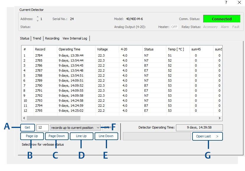
Legal notice
      The device described in this document is the property of Emerson.
      No part of the hardware, software, or documentation may be reproduced, transmitted, transcribed, stored in a retrieval system,
      or translated into any language or computer language, in any form or by any means, without prior written permission from
      Emerson.
      While great efforts have been made to ensure the accuracy and clarity of this document, Emerson assumes no liability resulting
      from any omissions in this document or from misuse of the information obtained herein. The information in this document has
      been carefully checked and is believed to be entirely reliable with all of the necessary information included. Emerson reserves the
      right to make changes to any products described herein to improve reliability, function, or design and reserves the right to revise
      this document and make changes from time to time in content hereof with no obligation to notify any persons of revisions or
      changes. Emerson does not assume any liability arising out of the application or any use of any product or circuit described herein;
      neither does it convey license under its patent rights or the rights of others.

Warranty
           1. Limited Warranty . Subject to the limitations contained in Section 2 (Limitation of Remedy and Liability) herein, Seller
              warrants that (a) the licensed firmware embodied in the Goods will execute the programming instructions provided by
              Seller; (b) that the Goods manufactured by Seller will be free from defects in materials or workmanship under normal use
              and care; and (c) Services will be performed by trained personnel using proper equipment and instrumentation for the
              particular Service provided. The foregoing warranties will apply until the expiration of the applicable warranty period.
              Sensors and detectors are warranted against defective parts and workmanship for 36 months for SharpEye 40/40C
              models and 60 months for SharpEye 40/40D models from the date of purchase.
              Products purchased by Seller from a third party for resale to Buyer (Resale Products) shall carry only the warranty
              extended by the original manufacturer. Buyer agrees that Seller has no liability for Resale Products beyond making a
              reasonable commercial effort to arrange for procurement and shipping of the Resale Products. If Buyer discovers any
              warranty defects and notifies Seller thereof in writing during the applicable warranty period, Seller shall, at its option, (i)
              correct any errors that are found by Seller in the firmware or Services; (ii) repair or replace FOB point of manufacture that
              portion of the Goods found by Seller to be defective; or (iii) refund the purchase price of the defective portion of the
              Goods/Services. All replacements or repairs necessitated by inadequate maintenance; normal wear and usage; unsuitable
              power sources or environmental conditions; accident; misuse; improper installation; modification; repair; use of
              unauthorized replacement parts; storage or handling; or any other cause not the fault of Seller, are not covered by this
              limited warranty and shall be replaced or repaired at Buyer's sole expense, and Seller shall not be obligated to pay any
              costs or charges incurred by Buyer or any other party except as may be agreed upon in writing in advance by Seller. All
              costs of dismantling, reinstallation, freight, and the time and expenses of Seller's personnel and representatives for site
              travel and diagnosis under this limited warranty clause shall be borne by Buyer unless accepted in writing by Seller. Goods
              repaired and parts replaced by Seller during the warranty period shall be in warranty for the remainder of the original
              warranty period or 90 days, whichever is longer. This limited warranty is the only warranty made by Seller and can be
              amended only in a writing signed by an authorized representative of Seller. The limited warranty herein ceases to be
              effective if Buyer fails to operate and use the Goods sold hereunder in a safe and reasonable manner and in accordance
              with any written instructions from the manufacturers. THE WARRANTIES AND REMEDIES SET FORTH ABOVE ARE
              EXCLUSIVE. THERE ARE NO REPRESENTATIONS OR WARRANTIES OF ANY KIND, EXPRESSED OR IMPLIED, AS TO
              MERCHANTABILITY, FITNESS FOR PARTICULAR PURPOSE, OR ANY OTHER MATTER WITH RESPECT TO ANY OF THE GOODS
              OR SERVICES.

           2. Limitation of Remedy and Liability SELLER SHALL NOT BE LIABLE FOR DAMAGES CAUSED BY DELAY IN PERFORMANCE. THE
              REMEDIES OF BUYER SET FORTH IN THE AGREEMENT ARE EXCLUSIVE. IN NO EVENT, REGARDLESS OF THE FORM OF THE
              CLAIM OR CAUSE OF ACTION (WHETHER BASED IN CONTRACT INFRINGEMENT, NEGLIGENCE, STRICT LIABILITY, OTHER
              TORT, OR OTHERWISE), SHALL SELLER'S LIABILITY TO BUYER AND/OR BUYER'S CUSTOMERS EXCEED THE PRICE TO BUYER
              OF THE SPECIFIC GOODS MANUFACTURED OR SERVICES PROVIDED BY SELLER GIVING RISE TO THE CLAIM OR CAUSE OF
              ACTION. BUYER AGREES THAT IN NO EVENT SHALL SELLER'S LIABILITY TO BUYER AND/OR BUYER'S CUSTOMERS EXTEND
              TO INCLUDE INCIDENTAL, CONSEQUENTIAL, OR PUNITIVE DAMAGES. THE TERM "CONSEQUENTIAL DAMAGES" SHALL
              INCLUDE, BUT NOT BE LIMITED TO, LOSS OF ANTICIPATED PROFITS, REVENUE OR USE AND COSTS INCURRED INCLUDING
              WITHOUT LIMITATION FOR CAPITAL, FUEL AND POWER, AND CLAIMS OF BUYER'S CUSTOMERS.

Technical support
      To get technical support for this product, contact your local Emerson representative or the Emerson Technical Support
      department at +1 866 347 3427 or safety.csc@emerson.com.

Abbreviations and acronyms

       Abbreviation or acronym                      Definition

       ATEX                                         Atmospheric explosives

2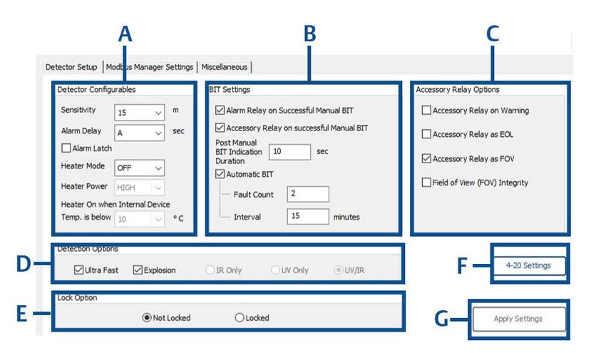
Abbreviation or acronym   Definition

AWG                       American wire gauge

BIT                       Built-in test

EMC                       Electromagnetic compatibility

EOL                       End of line

FOV                       Field of view
        ®
HART                      Highway addressable remote transducer - communication protocol

IAD                       Immune at any distance

IECEx                     International Electrotechnical Commission Explosion

IPA                       Isopropyl alcohol

IR                        Infrared

JP5                       Type of jet fuel

Latching                  Refers to relays remaining in the ON state even after the ON condition has been
                          removed.

LED                       Light emitting diode

LPG                       Liquified petroleum gas

mA                        Milliamps (0.001 amps)
            ®
Modbus                    Master-slave messaging structure

N/A                       Not applicable

NFPA                      National Fire Protection Association

NPT                       National pipe thread

RS485                     Communication protocol allowing bi-directional communication

PN                        Part number

SIL                       Safety integrity level

UNC                       Unified coarse thread

Vac                       Volts alternating current

Vdc                       Volts direct current

                                                                                                            3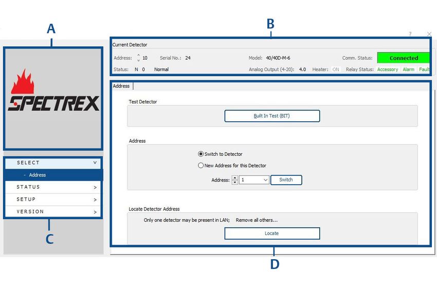
4
Reference Manual                                                                                                                                    Contents
00909-0200-4975                                                                                                                                     July 2022

Contents
Chapter 1        Introduction.............................................................................................................. 7
                 1.1 Product overview.........................................................................................................................7
                 1.2 Minimum requirements............................................................................................................... 7

Chapter 2        Initial setup................................................................................................................9
                 2.1 Download software......................................................................................................................9
                 2.2 Running the software...................................................................................................................9
                 2.3 Connect computer to the device..................................................................................................9
                 2.4 Connect device to harness cable................................................................................................ 10
                 2.5 Set up USB adapter.................................................................................................................... 10
                 2.6 Establish the COM port.............................................................................................................. 10
                 2.7 Connecting the device............................................................................................................... 12

Chapter 3        Operation................................................................................................................ 13
                 3.1 Screen overview.........................................................................................................................13
                 3.2 Perform manual BIT................................................................................................................... 15
                 3.3 Assign address to device............................................................................................................ 16
                 3.4 Switch device address................................................................................................................16
                 3.5 Locating the detector address....................................................................................................17
                 3.6 Status tab.................................................................................................................................. 17
                 3.7 Trend screen..............................................................................................................................18
                 3.8 Recording screen....................................................................................................................... 19
                 3.9 Detector setup tab.....................................................................................................................21

Chapter 4        Maintenance............................................................................................................ 27
                 4.1 Miscellaneous functions.............................................................................................................27
                 4.2 Update firmware........................................................................................................................27
                 4.3 Parameter update......................................................................................................................27
                 4.4 Set fixed current 4-20 values......................................................................................................28
                 4.5 Parameter download................................................................................................................. 29
                 4.6 Version information...................................................................................................................29
                 4.7 Service functions....................................................................................................................... 29

Appendix A       Reference data......................................................................................................... 31
                 A.1 Ordering information, specifications, and dimensional drawings...............................................31
                 A.2 Product certifications and installation drawings.........................................................................31
                 A.3 Status codes.............................................................................................................................. 31

Appendix B       Configurable options................................................................................................41
                 B.1 SharpEye 40/40C options...........................................................................................................41
                 B.2 SharpEye 40/40D options.......................................................................................................... 43

SharpEye 40/40                                                                                                                                                    5
Contents    Reference Manual
July 2022   00909-0200-4975

6                 Spectrex.net

Reference Manual                                                                               Introduction
00909-0200-4975                                                                                    July 2022

1                  Introduction
1.1                Product overview
                   Modbus® Manager is a customized software based on Modbus protocol over RS485, used
                   to configure the device to suit the customer needs, perform firmware upgrades and
                   provide troubleshooting information and functionality.
                   This guide describes the Modbus Manager and provides instructions on how to install,
                   operate, and maintain the software.
                   Note
                   The Modbus Manager software is for use with Spectrex SharpEye™ 40/40C and 40/40D
                   models only.

1.2                Minimum requirements
                   The minimum requirements for operating Modbus® Manager are as follows:
                   • Pentium® 3GHz
                   • Microsoft® Windows™ XP, 7, 8, or 10
                   • 2GB RAM
                   • 10GB hard disk free space
                   • Isolated RS-485 interface card to be defined as COM or an RS-485 converter to connect
                     to a standard COM port

SharpEye 40/40                                                                                            7
Introduction   Reference Manual
July 2022      00909-0200-4975

8                    Spectrex.net
Reference Manual                                                                                Initial setup
00909-0200-4975                                                                                    July 2022

2                  Initial setup
2.1                Download software
                   To download the Modbus® Manager, follow these steps:

                   Procedure
                      1. Go to Spectrex.net.
                      2. Using the site navigation, go to the relevant product page
                      3. Scroll down to Documents and Drawings.
                      4. Click SOFTWARE DOWNLOADS & DRIVERS.
                      5. Download the relevant file.

2.2                Running the software
                   Once the software file has been downloaded to your computer, create a shortcut in a
                   convenient location.
                   To run the software, double click on the executable file.

2.3                Connect computer to the device
                   Prerequisites
                   The computer must first be connected to the device using the RS485 harness cable before
                   performing any configuration or diagnostic operations on the device.

                   Procedure
                      1. Connect one end of the USB cable to one of the computer's USB ports.
                      2. Connect the other end of the USB cable to the USB serial (RS-485) adapter.
                      3. Connect the serial port of the adapter to the harness cable.

SharpEye 40/40                                                                                             9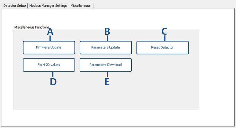
Initial setup Reference Manual
July 2022 00909-0200-4975
2.4 Connect device to harness cable
Procedure
1. Connect one side of the cable to detector Terminal 13 for RS-485 (+).
2. Connect the other side of the cable to detector Terminal 14 for RS-485 (-).
2.5 Set up USB adapter
CAUTION
Check that the D-connector adapter wiring is similar to the wiring shown (if not, adjust the
cable wiring to fit the desired adapter).
Procedure
1. If required, unscrew the cover of the USB adapter.
2. Set up jumpers using one of the following options.
•
•
3. Close the USB adapter cover.
4. Connect the cable.
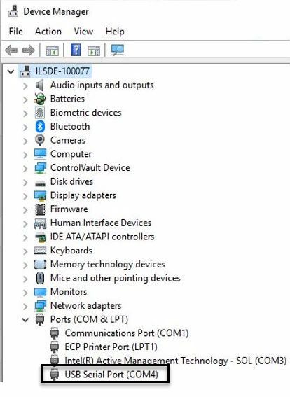
2.6 Establish the COM port
Prerequisites
When first connecting the harness, you will be prompted to select a COM port.
Procedure
1. Open Modbus® Manager.
10 Spectrex.netReference Manual Initial setup
00909-0200-4975 July 2022
2. Select Device Manager.
3. Select Ports.
4. Note to which COM the USB Serial Port is connected (this will vary among
computers).
5. From the Comport dropdown, select the relevant COM port.
6. Click the OK button.
SharpEye 40/40 11Initial setup Reference Manual
July 2022 00909-0200-4975
2.7 Connecting the device
The device must be connected to power and the RS485 should be connected to the
terminals according to the following table:
Function Wire color Terminal
RS485 (+) Red 13
RS485 (-) Black 14
12 Spectrex.netReference Manual Operation
00909-0200-4975 July 2022
3 Operation
3.1 Screen overview
Main screen
The left menu and top bar display on every screen. The left menu displays the brand name
and navigation controls; the top bar displays device information.
A. Device brand
B. Top bar (device information)
C. Left menu (navigation controls)
D. Settings and actions
SharpEye 40/40 13Operation Reference Manual
July 2022 00909-0200-4975
Top bar
The top bar contains information about the connected detector and appears on every
screen.
A. Current detector address
B. Detector serial number
C. Full detector model code
D. Communication status
E. Detector status
F. Analog output signal
G. Heater status
H. Relay status (green indicates de-energized state for alarm and ACC, energized for fault;
red indicates energized state for alarm and ACC, de-energized for fault).
14 Spectrex.netReference Manual Operation
00909-0200-4975 July 2022
Left menu
The left menu contains navigation information and the main sections are viewed on each
page. Subitems of the selected item are visible.
A. Device information
B. Device status
C. Device setup
D. Device and software version
3.2 Perform manual BIT
Procedure
In the Test Detector pane, click the Built-In Test (BIT) button.
Note
Performing BIT sets field of view (FOV). If the detector is not mounted in its final position,
BIT will need to be performed again.
SharpEye 40/40 15Operation Reference Manual
July 2022 00909-0200-4975
3.3 Assign address to device
Procedure
1. In the Address pane, select the New Address for the Detector radio button.
2. Use the Address dropdown to select the required address or enter the address in the
dropdown text box.
3. Click the Set New button.
3.4 Switch device address
Procedure
1. In the Address pane, if more than one detector is in the network and its address is
known, select the Switch to Detector radio button.
2. Use the Address dropdown to select the required address.
3. Click the Switch button.
Note
The detector address set by the factory is ‘1’. When locating the detector address,
only one detector should be connected.
16 Spectrex.netReference Manual Operation
00909-0200-4975 July 2022
Note
Alternatively, the up and down arrows can be used to switch the address without
clicking the Switch button.
3.5 Locating the detector address
If the detector address is not shown in the top menu or is not communicating, its address
can be located by clicking the Locate button within the Locate Detector Address pane.
Once communication is established, the current detector address will be shown in the top
menu.
Note
The Locate function requires that just a single detector be present in the RS485 LAN.
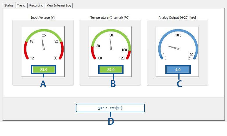
3.6 Status tab
This tab displays the device status for the currently selected detector.
SharpEye 40/40 17Operation Reference Manual
July 2022 00909-0200-4975
A. Shows current input voltage (in volts)
B. Shows current internal temperature (in degrees C or F according to setup)
C. Shows current 4-20 analog output (in mA)
D. Activates manual BIT
3.7 Trend screen
This screen shows the input voltage, internal temperature, and analog output live trends
according to the selected timeframe.
18 Spectrex.netReference Manual Operation
00909-0200-4975 July 2022
A. Displays all recorded data according to timeframe settings
B. Exports all data as ".txt" file
C. Opens timeframe settings
The timeframe settings can be adjusted by selecting the required values and clicking the
Reset button.
3.8 Recording screen
This screen allows data from detector currently connected to be recorded and exported
into a ".txt" or ".xls" file.
3.8.1 Record data
Procedure
1. Select the required recording mode.
SharpEye 40/40 19Operation Reference Manual
July 2022 00909-0200-4975
Note
The Fast mode provides recording at the best possible polling rate – around three
records per second.
2. Enter a comment and click the Insert button.
3. To end the recording, click the Stop button.
4. (Optional) Once recording has ended, click Open Recording Log.
Note
The file location is in the Modbus® directory installed on the computer in a file
entitled “Recordings”. SharpEye 40/40-I and M file names are QuadIRlog_YMDHMS
(Year, Month, Date, Hours, Minute, Second). SharpEye 40/40-LB and L4B file names
are prefaced with UVIRlog_YMDHMS (Year, Month, Date, Hours, Minute, Second).
The time stamp is according to GMT.
3.8.2 View internal log
The log displays the 12 most recent records without scrolling.
20 Spectrex.netReference Manual Operation
00909-0200-4975 July 2022
Procedure
To adjust number of records shown, change the number in the Get field and then press the
Get button.
A. Displays records according to selection in the records up to current position field
B. Scrolls up by page
C. Scrolls down by page
D. Scrolls up by line
E. Re-read by line
F. Select which records will be displayed when clicking Get button
G. Opens selected number of most recent records in ".txt" format
3.9 Detector setup tab
The detector is setup using the Detector Setup screen, in which configurable options, BIT
settings, Accessory Relay Options, Detection Options, Lock Option, and 4-20 Settings can
be changed.
Note
4-20mA settings – for fault mode, the default indication is 1mA, but may be changed to
0mA. A 4-20mA mode of 0mA is incompatible with HART® communication.
SharpEye 40/40 21Operation Reference Manual
July 2022 00909-0200-4975
A. Detector configurable settings
B. BIT settings
C. Accessory relay options
D. Detection options
E. Lock option
F. 4-20 settings
G. Click to save any changes made, becomes clickable once any setting has been changed
Note
Any unavailable options will be grayed out depending on specific detector model
connected.
3.9.1 Detector configurable settings
These detector parameters may be configured.
Sensitivity Sets the detector’s sensitivity (in meters/feet). A higher number
indicates greater sensitivity. See relevant product manual for more
information.
Heater mode Demister settings for clearing condensation from the lens. Choose
from On, Off, or Auto.
Default: Auto
Alarm delay The delay (in seconds) between detection of a signal and
activation of the alarm. Choose from 0, 3, 5, 10, 20, 30, or A (anti-
flare).
Default: A
Heater power Choose from high or low power (Spectrex 40/40D models only).
Default: High power
22 Spectrex.netReference Manual Operation
00909-0200-4975 July 2022
Heater on Temperature at which the demister is activated, if the heat mode
temperature is set to Auto.
Default: 5 °C
Enable alarm latch When selected, the alarm remains on even when the signal abates.
Default: Not enabled
3.9.2 BIT settings
These BIT settings may be configured.
Enable Automatic BIT When selected, the BIT runs automatically according to
the settings.
Default: Enabled
Fault count Number of sequential BIT faults before BIT fault indication.
Default: 3
Interval (in minutes) Duration between BIT cycles (maximum 60).
Default: 15
Activate alarm on Activates an alarm when a manual BIT is successfully
successful manual BIT completed.
Default: Not enabled
Activate accessory relay on Activates the accessory relay when a manual BIT is
successful manual BIT successfully completed.
Default: Not enabled
Post manual BIT indication Enables the user to configure the alarm duration
duration (in seconds) (maximum 60) after successful manual BIT.
Default: 3
SharpEye 40/40 23Operation Reference Manual
July 2022 00909-0200-4975
3.9.3 Accessory relay options
These options may be changed as described.
Activate When the detector’s status is warning, the accessory relay is
accessory relay activated.
on warning Default: Not enabled
Accessory relay When selected, the accessory relay is activated.
as EOL Default: Not enabled
Accessory relay When selected, the accessory relay is activated where FOV fault is
as FOV detected.(1)
Default: Not enabled
Field of view When enabled, will generate a notification if the detector's FOV has
(FOV) integrity changed by at least 15 degrees on the Y axis.(1)
Default: Not enabled
15 – 90 degrees – notification after 120 minutes
Above 90 degrees – notification after 20 minutes
Note
The FOV Integrity is monitored through all outputs:
• Device status (Modbus® and HART® protocols)
• Stepped 4-20mA—assign specific values (i.e. 3, 4, or 5mA) to
indicate the change
• Accessory relay—select the accessory relay activation for FOV
integrity change
Important
The FOV integrity should be enabled after the detector is installed
and its positioning is finalized.
3.9.4 Detection options
The type of detection can be determined using this section with the following
parameters.(2)
Fast According to model specifications, found in datasheet
Explosion According to model specifications, found in datasheet
IR only Single channel selection
UV only Single channel selection
UV/IR Double channel selection
(1) Available with Spectrex 40/40D models only.
(2) Available with Spectrex 40/40D models only.
24 Spectrex.netReference Manual Operation
00909-0200-4975 July 2022
3.9.5 Lock option
Modbus® Manager offers password protection for various maintenance and administrative
actions.
Not locked No password required to change detector settings or perform BIT
Locked Password required to change detector settings; opens dialog box for
setting passwords
Change To change the password, the previous password must be entered. If
passwords you do not have the previous password, contact the manufacturer to
receive a time-limited password to reset the password. Once received,
use the Enable Password reset button in the Version → Service menu.
When the “locked” option is selected, access to selected actions is controlled. There are
two independent permission types that allow access to the actions listed in Table 3-1 once
the detector is locked by passwords. When selecting the “locked” option, a dialog box
opens to enter the maintenance and admin passwords. Both passwords must be entered
by authorized personnel to complete the password setting process. Once completed, only
share the relevant password in accordance with internal policy.
Table 3-1: Permission Types
Action Permissions
Maintenance Admin
Reset detector Yes Yes
Change password Authorized personnel only
Manual BIT Yes No
Detector setup No Yes
Firmware update No Yes
Fix 4-20 scale values No Yes
Parameter upload No Yes
Important
Once locked, the actions can be activated only when entering the correct password. The
manufacturer will provide a time-limited password on authorized demand within five
business days.
3.9.6 4-20 Settings
Clicking the 4-20 Settings button opens a window showing current 4-20 settings. These
settings can be customized in accordance with the allowed nominal values.
Fault 0 or 1mA (if 0 is selected there will be no HART® communication)
Default: 1mA
BIT fault Fixed value, cannot be changed
FOV warning 3 – 5mA (must be ≤ the normal value)(3)
SharpEye 40/40 25Operation Reference Manual
July 2022 00909-0200-4975
Default: 4mA
Normal 4 or 5mA (must be ≥ the FOV value)
Default: 4mA
Pre-alarm warning 13 – 16mA (must be lower than alarm value)
Default: 16mA
Alarm 15 – 20mA (must be higher than warning)
Default: 20mA
Once values are entered, click the OK button to update the setup.
Note
The setup is only saved upon closing the 4-20 Settings dialog and subsequent application
of setup dialog.
3.9.7 Modbus® Manager settings
The Modbus Manager Settings screen is used to change COM port and the units throughout
the software.
Comport
Use this section to change the COM port as described in Establish the COM port.
Units
Use this section to change the units (i.e. metric or imperial) in which all measurements are
displayed.
Note
The application automatically restarts when the COM port is changed.
(3) Available with Spectrex 40/40D models only.
26 Spectrex.netReference Manual Maintenance
00909-0200-4975 July 2022
4 Maintenance
4.1 Miscellaneous functions
This screen provides access to various maintenance functions.
A. Perform firmware update with provided file
B. Upload parameters file
C. Detector reset
D. Fix 4-20 values
E. Download parameters file
4.2 Update firmware
Prerequisites
Firmware update file will be provided.
Procedure
1. Save file to your computer.
2. Switch to the required baud rate.
3. Click the Firmware update button.
4. Follow on-screen instructions to complete the process.
4.3 Parameter update
There is an optional feature to upload device parameters file with extension ".upm".
SharpEye 40/40 27Maintenance Reference Manual
July 2022 00909-0200-4975
Where required, this file will be provided by the manufacturer.
4.4 Set fixed current 4-20 values
4-20mA is factory calibrated with controlled and certified equipment; there is no need for
additional calibration. This process allows fixing of multimeter values to 4mA and 20mA
fixed values.
For different equipment used at the customer site over ±0.05mA, the 4-20mA output can
be fixed to match the reading indicated on the customer's multimeter. The reading can be
adjusted within ±0.05mA.
Procedure
1. Select the 4 mA radio button
2. Click Set fixed current.
3. Enter multimeter reading.
4. Click the Apply button.
5. Repeat steps Step 3 and Step 4 until you enter value within 4mA ±0.05.
Important
It is essential to enter the final value and click Apply. If this process remains
incomplete for five minutes, the detector will restart.
6. Select the 20 mA radio button.
7. Click Set fixed current.
8. Enter multimeter reading.
9. Click the Apply button.
10. Repeat steps Step 8 and Step 9 until you enter value within 20mA ±0.5.
Important
It is essential to enter the final value and click Apply. If this process remains
incomplete for five minutes, the detector will restart.
28 Spectrex.netReference Manual Maintenance
00909-0200-4975 July 2022
11. Click the Burn button to save the changes.
4.5 Parameter download
There is an optional feature to download device parameter files incorporated into one
folder located in the Modbus® Manager directory. This folder is saved to the subfolder with
the detector serial number included in the title.
Where required, this file will be provided by the manufacturer.
4.6 Version information
Detector information and the software version can be viewed on this screen.
4.7 Service functions
This screen provides access to various service functions.
SharpEye 40/40 29Maintenance Reference Manual
July 2022 00909-0200-4975
A. Enter time-limited password received from the manufacturer to enter tech-mode.
B. Enter time-limited password received from the manufacturer to reset password.
Note
If the application is closed after entering the password, a new password is required to re-
enter tech mode or reset password.
30 Spectrex.netReference Manual Reference data
00909-0200-4975 July 2022
A Reference data
A.1 Ordering information, specifications, and
dimensional drawings
To view current SharpEye 40/40 Series ordering information, specifications, and
dimensional drawings, follow these steps:
Procedure
1. Go to Spectrex.net/en-us/flame-gas-detectors-flame-detectors-40-40-series.
2. Select the appropriate product.
3. Scroll down to Documents and Drawings.
4. Select DATA SHEETS & BULLETINS.
5. Select the appropriate Product Data Sheet.
A.2 Product certifications and installation
drawings
To view current SharpEye 40/40 Series product certifications and installation drawings,
follow these steps:
Procedure
1. Go to Spectrex.net/en-us/flame-gas-detectors-flame-detectors-40-40-series.
2. Select the appropriate product.
3. Scroll down to Documents and Drawings.
4. Select CERTIFICATES & APPROVALS.
5. Select the appropriate document.
A.3 Status codes
SharpEye 40/40 C-I, C-M, D-I, and D-M Models
Status Description 4-20mA Analog Fault LED Test rate
output output relay indicator
S90 Start up 1mA 0v Open 4Hz Every start-up
blinking
orange
S91 Parameter restoration 1mA 0v Open 4Hz After
blinking parameters
orange burning
SharpEye 40/40 31Reference data Reference Manual
July 2022 00909-0200-4975
Status Description 4-20mA Analog Fault LED Test rate
output output relay indicator
S92 Restore from wrong 1mA 0v Open 4Hz After wrong
voltage blinking voltage
orange
V81 Wrong 5 VOLT(1) 1mA 0v Open 4Hz Every 30msec
blinking
orange
V82 Wrong 9 VOLT(1) 1mA 0v Open 4Hz Every 30msec
blinking
orange
V83 Wrong vin(2) 1mA 0v Open 4Hz Every 30msec
blinking
orange
P71 Program memory CRC 1mA 0v Open 4Hz At start-up
failure blinking
orange
P72 Faulty parameters 1mA 0v Open 4Hz At start-up or
blinking upon setup/
orange parameters
burning
P74 RAM CRC failure 1mA 0v Open 4Hz Every 30msec
blinking
orange
P75 None of the 1mA 0v Open 4Hz At start-up
parameters exist blinking
orange
P76 RAM parameters CRC 1mA 0v Open 4Hz Every hour
failure blinking
orange
F31 Sensor 4.5µ circuit 1mA 0v Open 4Hz Auto/manual BIT
failure – no signal blinking
orange
F32 Sensor 5µ circuit 1mA 0v Open 4Hz Auto/manual BIT
failure – no signal blinking
orange
F33 Sensor 4µ, or 2.4µ for 1mA 0v Open 4Hz Auto/manual BIT
Hydrogen circuit blinking
failure – no signal orange
F34 Sensor 4.4µ, or 3µ for 1mA 0v Open 4Hz Auto/manual BIT
Hydrogen circuit blinking
failure – no signal orange
F38 Wrong AFE offset 1mA 0v Open 4Hz Every 30msec
blinking
orange
32 Spectrex.netReference Manual Reference data
00909-0200-4975 July 2022
Status Description 4-20mA Analog Fault LED Test rate
output output relay indicator
F46 IR signal Amp stuck at 1mA 0v Open 4Hz Every BIT
one failure blinking
orange
F47 Failure SPI COM with 1mA 0v Open 4Hz Every 30msec
AFE blinking
orange
F48 AFE stuck at 1 1mA 0v Open 4Hz Every 30msec
blinking
orange
F51 Sensor 4.5 noise 1mA 0v Open 4Hz Every 30msec
blinking
orange
F52 Sensor 5 noise 1mA 0v Open 4Hz Every 30msec
blinking
orange
F53 Sensor 4µ, or 2.4µ for 1mA 0v Open 4Hz Every 30msec
Hydrogen noise blinking
orange
F54 Sensor 4.4µ, or 2.4µ 1mA 0v Open 4Hz Every 30msec
for Hydrogen noise blinking
orange
F55 Sensor 4.5 and 5 short 1mA 0v Open 4Hz Every BIT
circuit blinking
orange
F56 Sensor 4.5 and 4 short 1mA 0v Open 4Hz Every BIT
circuit blinking
orange
F57 Sensor 4 and 5 short 1mA 0v Open 4Hz Every BIT
circuit blinking
orange
F58 Sensor 4.4 and 4.55 1mA 0v Open 4Hz Every BIT
short circuit blinking
orange
F59 Sensor 4.4 and 4 short 1mA 0v Open 4Hz Every BIT
circuit blinking
orange
F60 Sensor 4.5 and 5 short 1mA 0v Open 4Hz Every BIT
circuit blinking
orange
N0 Normal 4mA 2v Close 1Hz Every 30msec
blinking
green
N1 Constant external BIT 4mA 2v Close 4Hz Every 30msec
blinking
orange
SharpEye 40/40 33Reference data Reference Manual
July 2022 00909-0200-4975
Status Description 4-20mA Analog Fault LED Test rate
output output relay indicator
N2 Wrong ambient 4mA 2v Close 4Hz Every 30msec
temperature blinking
orange
N3 4-20mA circuit failure 0 mA 2v Close 4Hz Every 30msec
blinking
orange
N4 Fault relay failure 4mA 2v Open 4Hz Every 30msec
blinking
orange
N5 Accessory relay failure 4mA 2v Open 4Hz Every 30msec
blinking
orange
N6 Alarm relay failure 4mA 2v Open 4Hz Every 30msec
blinking
orange
N7 Heater failure 4mA 2v Close 4Hz Every 30msec
blinking
orange
N8 BIT failure 2mA 0v Open 4Hz Every BIT
blinking
orange
N9 Damaged BIT lamp 2mA 0v Open 4Hz Every BIT
blinking
orange
N11 FOV failure 4mA 2v Close 1Hz Every 30msec
blinking
green
N12 Missed ADC reading 4mA 2v Close 1Hz Every 30msec
blinking
green
N13 Analog output failure 4mA 0v Close 4Hz Every 30msec
blinking
orange
N18 FOV warning 4mA 2v Close 1Hz Every 30msec
blinking
green
B0 Automatic BIT 4mA 2v Close 1Hz Every BIT
blinking
green
M0 Manual BIT 4mA 2v Close 1Hz Every BIT
blinking
green(3)
E0 End of BIT 4mA 2v Close 1Hz Every BIT
blinking
green(3)
34 Spectrex.netReference Manual Reference data
00909-0200-4975 July 2022
Status Description 4-20mA Analog Fault LED Test rate
output output relay indicator
G0 Pre-alarm 4mA 2v Close 1Hz Every 30msec
blinking
green
T0 Alarm delay 16mA 2v Close 2Hz Every 30msec
blinking red
W0 Warning 16mA 2v Close 2Hz Every 30msec
blinking red
A0 Alarm 20mA 5v Close Constant Every 30msec
red
L0 Latch 20mA 5v Close Constant Every 30msec
red
Z0 Post-alarm: Benzene 4mA 2v Close 1Hz Every 30msec
blinking
green
J0 Anti-flare (4) 2v Close 1Hz Every 30msec
blinking
green
X0 Explosion 20mA 5v Close Constant Every 0.23msec
red
(1) The detector turns to V81, V82 after two minutes.
(2) The detector turns to V83 after 50 seconds.
(3) Unless in Setup table define constant red.
(4) 4mA if from state "N', 16mA if from state "T".
SharpEye 40/40 -C-LB, C-L4B, D-LB, and D-L4B Models
Status Description 4-20mA Analog Fault LED Test rate
output output relay indicator
S90 Start up 1mA 0v Open 4Hz Every start-up
blinking
orange
S91 Parameter restoration 1mA 0v Open 4Hz After burning a
blinking new parameter
orange
S92 Restore from wrong 1mA 0v Open 4Hz After wrong
voltage blinking voltage
orange
V81 Wrong 5 VOLT(1) 1mA 0v Open 4Hz Every 30msec
blinking
orange
V82 Wrong 9 VOLT(1) 1mA 0v Open 4Hz Every 30msec
blinking
orange
SharpEye 40/40 35Reference data Reference Manual
July 2022 00909-0200-4975
Status Description 4-20mA Analog Fault LED Test rate
output output relay indicator
V83 Wrong vin(2) 1mA 0v Open 4Hz Every 30msec
blinking
orange
P71 Program memory CRC 1mA 0v Open 4Hz At start-up
failure blinking
orange
P72 Faulty parameters 1mA 0v Open 4Hz At start-up or
blinking upon setup/
orange parameters
burning
P74 RAM CRC failure 1mA 0v Open 4Hz Every 30msec
blinking
orange
P75 None of the 1mA 0v Open 4Hz At start-up
parameters exist blinking
orange
P76 RAM parameters CRC 1mA 0v Open 4Hz Every hour
failure blinking
orange
F38 Wrong AFE offset 1mA 0v Open 4Hz Every 30msec
blinking
orange
F41 Constant UV 1mA 0v Open 4Hz Every 30msec
blinking
orange
F42 Noisy UV 1mA 0v Open 4Hz Every 30msec
blinking
orange
F43 UV high voltage 1mA 0v Open 4Hz Every 30msec
failure blinking
orange
F44 IR sensor failure – no 1mA 0v Open 4Hz Auto/manual BIT
signal blinking
orange
F45 IR circuit shortcut 1mA 0v Open 4Hz Every 30msec
failure blinking
orange
F46 IR signal Amp stuck at 1mA 0v Open 4Hz Auto/manual BIT
one failure blinking
orange
F47 Constant IR signal 1mA 0v Open 4Hz Every 30msec
blinking
orange
36 Spectrex.netReference Manual Reference data
00909-0200-4975 July 2022
Status Description 4-20mA Analog Fault LED Test rate
output output relay indicator
F48 UV pulse stuck at 1 1mA 0v Open 4Hz Every 30msec
blinking
orange
F49 Digi pot failure 1mA 0v Open 4Hz Every 30msec
blinking
orange
F51 UV tube broken/ 1mA 0v Open 4Hz Every 30msec
constant UV pulse blinking
orange
F52 AFE (Analog Front 1mA 0v Open 4Hz Every 30msec
End) failure blinking
orange
F53 Bad SPI COM 1mA 0v Open 4Hz Every 30msec
blinking
orange
N0 Normal 4mA 2v Close 1Hz Every 30msec
blinking
green
N1 Constant external BIT 4mA 2v Close 4Hz Every 30msec
blinking
orange
N2 Wrong ambient 4mA 2v Close 4Hz Every 30msec
temperature blinking
orange
N3 4-20mA circuit failure 0 mA 2v Close 4Hz Every 30msec
blinking
orange
N4 Fault relay failure 4mA 2v Open 4Hz Every 30msec
blinking
orange
N5 Accessory relay failure 4mA 2v Open 4Hz Every 30msec
blinking
orange
N6 Alarm relay failure 4mA 2v Open 4Hz Every 30msec
blinking
orange
N7 Heater failure 4mA 2v Close 4Hz Every 30msec
blinking
orange
N8 IR or UV BIT failure 2mA 0v Open 4Hz Every BIT
blinking
orange
N9 Lamp BIT failure 2mA 0v Open 4Hz Every BIT
blinking
orange
SharpEye 40/40 37Reference data Reference Manual
July 2022 00909-0200-4975
Status Description 4-20mA Analog Fault LED Test rate
output output relay indicator
N10 UV LED failure 3mA 0v Open 4Hz Every BIT
blinking
orange
N11 FOV failure 4mA 2v Close 1Hz Every 30msec
blinking
green
N12 Missed ADC reading 4mA 2v Close 1Hz Every 30msec
blinking
green
N13 Analog output failure 4mA 0v Close 4Hz Every 30msec
blinking
orange
N18 FOV warning 4mA 2v Close 1Hz Every 30msec
blinking
green
I0 IR level 8mA 2v Close 1Hz Every 30msec
blinking
green
U0 UV level 12mA 2v Close 1Hz Every 30msec
blinking
green
B0 IR/UV automatic BIT 4mA 2v Close 1Hz Every IR BIT
blinking
green
M0 IR/UV manual BIT 4mA 2v Close 1Hz Every IR BIT
blinking
green(3)
E0 IR/UV end of BIT 4mA 2v Close 1Hz Every IR BIT
blinking
green(3)
G0 Temperature gradient 4mA 2v Close 1Hz Every 30msec
blinking
green
T0 Alarm delay 16mA 2v Close 2Hz Every 30msec
blinking red
W0 Warning 16mA 2v Close 2Hz Every 30msec
blinking red
A0 Alarm 20mA 5v Close Constant Every 30msec
red
L0 Latch 20mA 5v Close Constant Every 30msec
red
Z0 Benzene 4mA 2v Close 1Hz Every 30msec
blinking
green
38 Spectrex.netReference Manual Reference data
00909-0200-4975 July 2022
Status Description 4-20mA Analog Fault LED Test rate
output output relay indicator
J0 Anti-flare (4) 2v Close 1Hz Every 30msec
blinking
green
X0 Explosion 20mA 5v Close Constant Every 0.23msec
red
SharpEye 40/40 39Reference data Reference Manual July 2022 00909-0200-4975 40 Spectrex.net
Reference Manual                                                                          Configurable options
00909-0200-4975                                                                                      July 2022

B                  Configurable options
B.1                SharpEye 40/40C options
                   This section contains values for configurable options. Asterisks (*) indicate default values
                   unless otherwise noted.

                   Option                          SharpEye model
                                                   40/40C-I        40/40C-M       40/40C-LB       40/40C-L4B
                   Detection sensitivity           • 3m                           • 3m            • 3m
                                                   • 15m                          • 15m*          • 15m
                                                   • 30m*                                         • 28m*
                                                   • 45m
                                                   • 65m

                   Alarm delay (in seconds)        • 0
                                                   • A (Anti-flare)*
                                                   • 3
                                                   • 5
                                                   • 10
                                                   • 15
                                                   • 20
                                                   • 30

                   Alarm latching                  • Yes
                                                   • No*

                   Heated optics                   • Constantly on
                                                   • Constantly off
                                                   • Auto on: 32 °F (0 °C)
                                                   • Auto on: 41 °F (5 °C)*
                                                   • Auto on: 50 °F (10 °C)
                                                   • Auto on: 59 °F (15 °C)
                                                   • Auto on: 68 °F (20 °C)
                                                   • Auto on: 77 °F (25 °C)
                                                   • Auto on: 86 °F (30 °C)

                   Heated power                    • Low
                                                   • High*

SharpEye 40/40                                                                                                 41
Configurable options Reference Manual
July 2022 00909-0200-4975
Option SharpEye model
40/40C-I 40/40C-M 40/40C-LB 40/40C-L4B
Alarm relay on successful • Yes
manual BIT
• No*
Accessory relay on successful • Yes
manual BIT
• No*
Post manual BIT indication 3–60
duration (in seconds) Default value: 3
Enable automatic BIT • Yes*
• No
Fault count 0–10
Default value: 3
Bit interval (in minutes) 1–60
Default value: 15
Accessory relay options • Disabled*
• Accessory relay on warning
• Accessory relay as EOL
Lock option • Not locked*
• Locked
4-20mA settings
Fault • 0
• 1*
BIT fault 2*
Normal • 4*
• 5
Warning • 16*
• Custom
Alarm • 20*
• Custom
42 Spectrex.netReference Manual Configurable options
00909-0200-4975 July 2022
B.2 SharpEye 40/40D options
This section contains values for configurable options. Asterisks (*) indicate default values
unless otherwise noted.
Option SharpEye model
40/40D-I 40/40D-M 40/40D-LB 40/40D-L4B
Detection sensitivity • 3m • 3m
• 15m • 15m
• 30m* • 28m*
• 45m
• 65m
• 90m
Alarm delay (in seconds) • 0
• A (Anti-flare)*
• 3
• 5
• 10
• 15
• 20
• 30
Alarm latching • Yes
• No*
Heated optics • Constantly on
• Constantly off
• Auto on: 32 °F (0 °C)
• Auto on: 41 °F (5 °C)*
• Auto on: 50 °F (10 °C)
• Auto on: 59 °F (15 °C)
• Auto on: 68 °F (20 °C)
• Auto on: 77 °F (25 °C)
• Auto on: 86 °F (30 °C)
Heated power • Low
• High*
Alarm relay on successful • Yes
manual BIT
• No*
SharpEye 40/40 43Configurable options Reference Manual
July 2022 00909-0200-4975
Option SharpEye model
40/40D-I 40/40D-M 40/40D-LB 40/40D-L4B
Accessory relay on successful • Yes
manual BIT
• No*
Post manual BIT indication 3–60
duration (in seconds) Default value: 3
Enable automatic BIT • Yes*
• No
Fault count 0–10
Default value: 3
Bit interval (in minutes) 1–60
Default value: 15
Detection options • Standard* • Standard*
• Fast • Fast
• Explosion • Explosion
• IR only
• UV only
• UV/IR*
Accessory relay options • Disabled*
• Accessory relay on warning
• Accessory relay as EOL
• Accessory relay as FOV
• FOV integrity
Lock option • Not locked*
• Locked
4-20mA settings
Fault • 0
• 1*
BIT fault 2*
Normal • 4*
• 5
Warning • 16*
• Custom
Alarm • 20*
• Custom
44 Spectrex.netReference Manual Configurable options
00909-0200-4975 July 2022
Option SharpEye model
40/40D-I 40/40D-M 40/40D-LB 40/40D-L4B
FOV • 3
• 4*
• 5
SharpEye 40/40 4500909-0200-4975
Rev. AB
2022
For more information: Emerson.com
©2022 Emerson. All rights reserved.
Spectrex is a mark of one of the Emerson family of companies.
All other marks are the property of their respective owners.You can also read