Rosemount 5300 Level Transmitter - Guided Wave Radar - Emerson
←
→
Page content transcription
If your browser does not render page correctly, please read the page content below
Quick Start Guide
                        00825-0100-4530, Rev HB
                                   January 2022

Rosemount™ 5300 Level Transmitter

Guided Wave Radar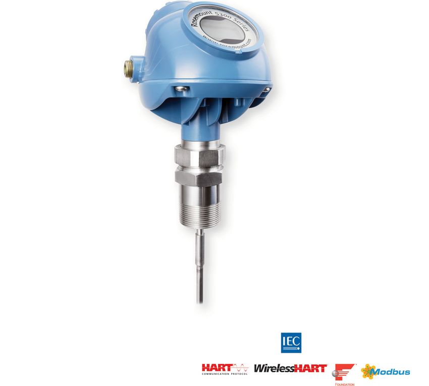
Quick Start Guide                                                                                                          January 2022

Contents
About this guide...........................................................................................................................3
                                                ®
Confirm system readiness (HART only)....................................................................................... 5
Mount transmitter on tank........................................................................................................... 6
Prepare the electrical connections..............................................................................................11
Connect wiring and power up.....................................................................................................19
Configure................................................................................................................................... 23
Safety Instrumented Systems (4-20 mA only).............................................................................26
Adjust probe length................................................................................................................... 27
Product certifications................................................................................................................. 30

2                                                                                            Rosemount 5300 Level Transmitter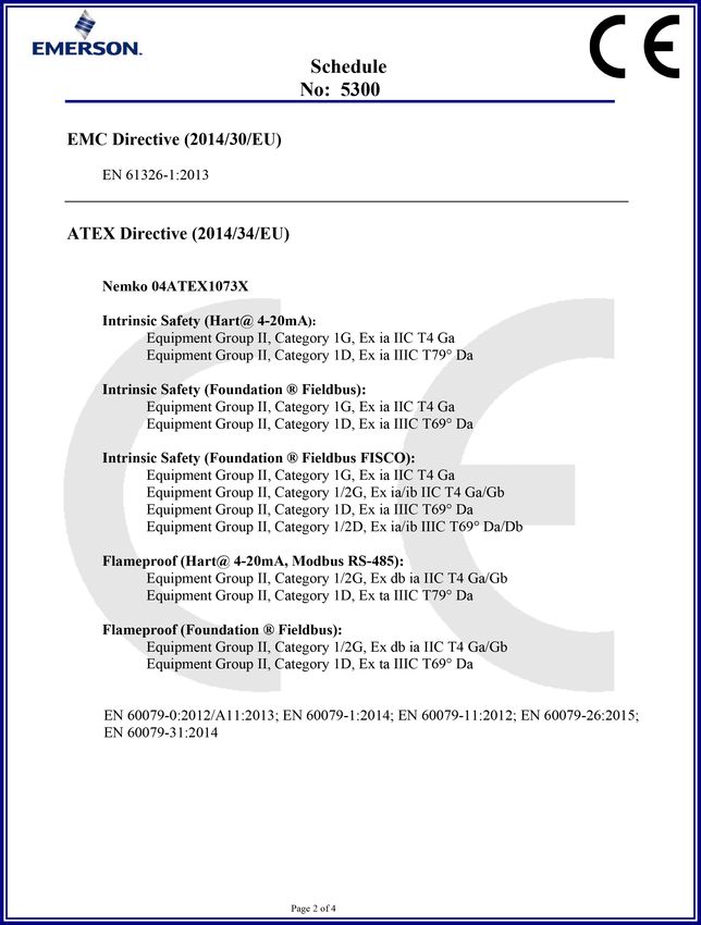
January 2022                                                                Quick Start Guide

1         About this guide
           This Quick Start Guide provides basic guidelines for the Rosemount 5300
           Level Transmitter. Refer to the Rosemount 5300 Reference Manual for more
           instructions. The manual and this guide are also available electronically on
           Emerson.com/Rosemount.

               WARNING
           Failure to follow safe installation and servicing guidelines could result in
           death or serious injury.
           • Ensure the transmitter is installed by qualified personnel and in
             accordance with applicable code of practice.
           • Use the equipment only as specified in this Quick Start Guide and the
             Reference Manual. Failure to do so may impair the protection provided
             by the equipment.
           • Any substitution of non-recognized parts may jeopardize safety. Repair
             (e.g. substitution of components) may also jeopardize safety and is not
             allowed under any circumstances.
           Explosions could result in death or serious injury.
           • Verify that the operating atmosphere of the transmitter is consistent
             with the appropriate hazardous locations certifications.
           • To prevent ignition of flammable or combustible atmospheres,
             disconnect power before servicing.
           • Before connecting a handheld communicator in an explosive
             atmosphere, ensure the instruments are installed in accordance with
             intrinsically safe or non-incendive field wiring practices.
           • To avoid process leaks, only use the O-ring designed to seal with the
             corresponding flange adapter.
           Electrical shock could cause death or serious injury.
           • Avoid contact with the leads and terminals. High voltage that may be
             present on leads can cause electrical shock.
           • Ensure the mains power to the transmitter is off and the lines to any
             other external power source are disconnected or not powered while
             wiring the transmitter.
           • Ground device on non-metallic tanks (e.g. fiberglass tanks) to prevent
             electrostatic charge build-up.

Quick Start Guide                                                                          3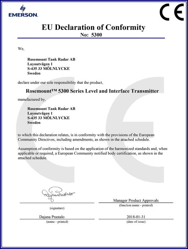
Quick Start Guide                                                           January 2022

             WARNING
          Probes with non-conducting surfaces.
          • Probes covered with plastic and/or with plastic discs may generate an
            ignition-capable level of electrostatic charge under certain extreme
            conditions. Therefore, when the probe is used in a potentially explosive
            atmosphere, appropriate measures must be taken to prevent
            electrostatic discharge.
          Eliminate the risk of ESD discharge prior to dismounting the transmitter
          head from the probe.
          • Probes may generate an ignition-capable level of electrostatic charge
            under extreme conditions. During any type of installation or
            maintenance in a potentially explosive atmosphere, the responsible
            person should ensure that any ESD risks are eliminated before
            attempting to separate the probe from the transmitter head.

4                                                        Rosemount 5300 Level Transmitter
January 2022                                                                       Quick Start Guide

2         Confirm system readiness (HART® only)
2.1       Confirm HART® revision capability
           If using HART based control or asset management systems, confirm the
           HART capability of those systems prior to transmitter installation. Not all
           systems are capable of communicating with HART Revision 7 protocol.
           Transmitters with a firmware version 2F0 or later can be configured for
           either HART Revision 5 or 7.

2.2       Confirm correct device driver
           Procedure
           • Verify that the latest Device Driver (DD/DTM™) is loaded on your systems
             to ensure proper communication. See Table 2-1.
           • Download the latest Device Driver from Emerson.com/DeviceInstallKits.
               Table 2-1: Rosemount 5300 Device Revisions and Files

                Firmware version (1)        Find Device Driver

                                            HART® Universal              Device Revision (2)
                                            Revision

                2F0 or later                7                            4

                                            5                            3

                2A2 - 2E0                   5                            3

               (1) Firmware version is printed on the transmitter head label (e.g. SW 2E0), or
                   can be found in Rosemount Radar Master (select Device → Properties).
               (2) Device revision is printed on the transmitter head label (e.g. HART Dev Rev
                   4).

2.3       Switch HART® revision mode
           If the HART configuration tool is not capable of communicating with HART
           Revision 7, the device will load a generic menu with limited capability. To
           switch the HART revision mode from the generic menu:

           Procedure
               1. Locate the “Message” field.
               2. In the Message field, enter HART5 or HART7 and then 27 trailing
                  spaces.

Quick Start Guide                                                                                 5
Quick Start Guide                                                              January 2022

3         Mount transmitter on tank
          For flexible single lead probes ordered with weight unmounted (option code
          WU), refer to Adjust probe length before mounting the transmitter.

3.1       Threaded/Flange/Tri-Clamp® tank connection
          Procedure
              1. Seal and protect the threads.
                       Only for NPT threaded tank connection.
                    Use anti-seize paste or PTFE tape according to your site procedures.

              2. Mount the device on tank.
                         $                                      %

                                                                          &

                        A. NPT
                        B. Flange
                        C. Gasket

6                                                           Rosemount 5300 Level Transmitter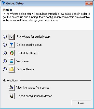
January 2022                                                          Quick Start Guide

                       $                                          %

                                 &                                    &

                      A. Tri-Clamp
                      B. BSP/G
                      C. Gasket

               3. (Optional) Adjust display orientation.

               4. Tighten the nut.

                                        Torque 30 ft-lb (40 Nm)

Quick Start Guide                                                                    7
Quick Start Guide January 2022
3.2 Install remote housing
Procedure
1. Carefully remove the transmitter.
2. Mount the probe on tank.
$
A. Gasket
3. Mount the remote connection on the probe.
Torque 30 ft-lb (40 Nm)
55 mm
8 Rosemount 5300 Level TransmitterJanuary 2022 Quick Start Guide
4. Mount the bracket to the pipe.
A
4X
B
A. Horizontal pipe
B. Vertical pipe
5. Fasten the housing support.
3X
6. Mount the transmitter head.
Torque 30 ft-lb (40 Nm)
55 mm
Quick Start Guide 9Quick Start Guide January 2022
3.3 Bracket mounting
Procedure
1. Mount the bracket to the pipe/wall.
On pipe:
A
4X
B
A. Horizontal pipe
B. Vertical pipe
On wall:
4X
2. Mount the transmitter with probe to the bracket.
3X
10 Rosemount 5300 Level TransmitterJanuary 2022 Quick Start Guide
4 Prepare the electrical connections
4.1 Cable gland/conduit
For explosion-proof/flameproof installations, only use cable glands or
conduit entry devices certified explosion-proof or flameproof.
4.2 Power supply (Vdc)
Approval type HART® FOUNDATION™ RS-485 with
Fieldbus Modbus®
None 16-42.4 9-32 8-30 (max. rating)
Non-sparking/ 16-42.4 9-32 N/A
energy limited
Intrinsically safe 16-30 9-30 N/A
FISCO N/A 9-17.5 N/A
Explosion-proof/ 20-42.4 16-32 8-30 (max. rating)
Flameproof
Quick Start Guide 11Quick Start Guide January 2022
4.3 4-20 mA/HART® communication
4.3.1 Wiring diagram
Figure 4-1: Wiring Diagram for 4-20 mA/HART®
$
&
' )
- - -
+ + +
(
%
A. Handheld communicator
B. Approved IS barrier (for Intrinsically Safe installations only)
C. HART modem
D. Current meter
E. Load resistance (≥250 Ω)
F. Power supply
Note
Rosemount 5300 Level Transmitters with flameproof/explosion-proof
output have a built-in barrier; no external barrier needed.
4.3.2 Load limitations
For HART® communication, a minimum loop resistance of 250 Ω is required.
Maximum loop resistance is determined by the voltage level of the external
power supply, as given by the following diagrams:
12 Rosemount 5300 Level TransmitterJanuary 2022 Quick Start Guide
Figure 4-2: Intrinsically Safe Installations
$
&
%
A. Loop Resistance (Ohms)
B. External Power Supply Voltage (Vdc)
C. Operating region
Figure 4-3: Non-Hazardous and Non-Sparking/Energy Limited
Installations
$
&
%
A. Loop Resistance (Ohms)
B. External Power Supply Voltage (Vdc)
C. Operating region
Quick Start Guide 13Quick Start Guide January 2022
Figure 4-4: Explosion-Proof /Flameproof (Ex d) Installations
$
&
%
A. Loop Resistance (Ohms)
B. External Power Supply Voltage (Vdc)
C. Operating region
Note
For the Ex d case, the diagram is only valid if the load resistance is at the +
side and if the - side is grounded, otherwise the maximum load resistance is
limited to 435 Ω.
14 Rosemount 5300 Level TransmitterJanuary 2022 Quick Start Guide
4.4 FOUNDATION™ Fieldbus
4.4.1 Wiring diagram
Figure 4-5: Wiring Diagram for FOUNDATION Fieldbus
$
&
+ + + '
- - -
%
A. Handheld communicator
B. Approved IS barrier (for Intrinsically Safe installations only)
C. FOUNDATION Fieldbus modem
D. Power supply
Note
Rosemount 5300 Level Transmitters with flameproof/explosion-proof
output have a built-in barrier; no external barrier needed.
4.5 RS-485 with Modbus® communication
See the Rosemount 5300 Reference Manual for details.
4.5.1 Power consumption
• < 0.5 W (with HART address=1)
• < 1.2 W (incl. four HART slaves)
Quick Start Guide 15Quick Start Guide January 2022
4.5.2 Wiring diagram
Figure 4-6: Wiring Diagram for RS-485 with Modbus®
+
)
*
+
- (
$
& ' &
%
A. “A” line
B. “B” line
C. 120 Ω
D. RS-485 Bus
E. Power supply
F. HART -
G. HART +
H. If it is the last transmitter on the bus, connect the 120 Ω termination
resistor.
Note
Rosemount 5300 Level Transmitters with Flameproof/Explosion-proof
output have a built-in barrier; no external barrier needed.(1)
4.6 Grounding
Ensure grounding is done (including IS ground inside Terminal
compartment) according to Hazardous Locations Certifications, national
and local electrical codes.
(1) An external galvanic isolator is always recommended to be used for Flameproof/
Explosion-proof installations.
16 Rosemount 5300 Level TransmitterJanuary 2022 Quick Start Guide
Grounding is essential for Hazardous Location safety (even for Flameproof/
Explosion Proof versions). A ground cable with a cross-sectional area of ≥ 4
mm² must be used.
Note
Grounding the transmitter via threaded conduit connection may not provide
sufficient ground.
Note
In the explosion-proof/flameproof version, the electronics is grounded via
the transmitter housing. After installation and commissioning ensure that
no ground currents exist due to high ground potential differences in the
installation.
Transmitter housing grounding
The most effective transmitter housing grounding method is a direct
connection to earth ground with minimal (< 1 Ω) impedance. There are two
grounding screw connections provided (see Figure 4-7).
Figure 4-7: Ground Screws
$ %
&
A. Internal ground screw, torque 28 in-lb (3.2 Nm)
B. Internal ground twin-screws for Hazardous locations certifications CSA/
Canada, torque 10 in-lb (1.2 Nm)
C. External ground screw, torque 36 in-lb (4.1 Nm)
Signal cable shield grounding
Ensure the instrument cable shield is:
• trimmed close and insulated from touching the transmitter housing.
• continuously connected throughout the segment.
• connected to a good earth ground at the power supply end.
Quick Start Guide 17Quick Start Guide January 2022
Figure 4-8: Cable Shield and Signal Wire Insulation
%
( %
$
&
& &
'
A. Insulate shield
B. Minimize distance
C. Trim shield and insulate
D. Connect shield back to the power supply ground
E. Signal cable insulation must extend into the interior of each separate
terminal
18 Rosemount 5300 Level TransmitterJanuary 2022 Quick Start Guide
5 Connect wiring and power up
Procedure
1. Confirm the power supply is switched off.
2. Remove the terminal block cover.
3. Remove the plastic plugs.
4. Pull the cable through the cable gland/conduit.
Adapters are required if M20 glands are used.
Quick Start Guide 19Quick Start Guide January 2022
5. Connect the cable wires (see Figure 4-1, Figure 4-5, and Figure 4-6).
Torque 7 in-lb (0.8 Nm)
6. Ensure proper grounding (see Grounding).
7. Use the enclosed metal plug to seal any unused port.
Note
Apply PTFE tape or other sealant to the threads.
20 Rosemount 5300 Level TransmitterJanuary 2022 Quick Start Guide
8. Tighten the cable gland.
Note
Apply PTFE tape or other sealant to the threads.
Note
Be sure to arrange the wiring with a drip loop.
9. Mount the cover making sure the cover is secure to meet
explosion-proof requirements.
Quick Start Guide 21Quick Start Guide January 2022
10. Turn the jam screw counterclockwise until it contacts the cover.
Required for flameproof installations only.
11. Connect the power supply.
22 Rosemount 5300 Level TransmitterJanuary 2022 Quick Start Guide
6 Configure
Basic configuration can easily be done either with Rosemount Radar Master,
a handheld communicator, AMS Device Manager, DeltaV™, or any other DD
(Device Description) or DTM™ compatible host system. For advanced
configuration features, Rosemount Radar Master is recommended.
Rosemount Radar Master is available here:
Emerson.com/RosemountRadarMaster.
6.1 Configure using Rosemount Radar Master
Procedure
1. Start Rosemount Radar Master.
2. Connect to the desired transmitter.
3. In the Guided Setup window, click Run Wizard for guided setup and
follow the instructions.
4. In the Guided Setup window, continue with steps 2 to 5.
5. Click View live values from device to verify that the transmitter
works correctly.
Quick Start Guide 23Quick Start Guide January 2022
6.2 Configure using AMS Device Manager or handheld
communicator
6.2.1 Connect to device using AMS Device Manager
Procedure
1. Start AMS Device Manager.
2. Select View → Device Connection View.
3. In the Device Connection View, double-click the modem icon.
4. Double-click the device icon.
6.2.2 Connect to device using a handheld communicator
Procedure
Turn on the handheld communicator and connect to the device.
6.2.3 Configure device
Configure HART® devices
Procedure
1. Select Configure → Guided Setup.
2. Select Level Measurement Setup and follow the instructions.
3. Select Device Specific Setup.
4. Run Verify Level to check your level measurement.
5. (Optional) Select Volume Setup.
6. (Optional) Select Display Setup.
FOUNDATION™ Fieldbus
Procedure
1. Select Configure → Guided Setup.
2. Select Level Measurement Setup and follow the instructions.
3. (Optional) Select Volume Calculation Setup.
4. (Optional) Select Device Specific Setup.
5. (Recommended) Select Restart Measurement.
24 Rosemount 5300 Level TransmitterJanuary 2022 Quick Start Guide
6.3 FOUNDATION™ Fieldbus parameters
Table 6-1: FOUNDATION Fieldbus Parameters
Function Parameter
Probe type TRANSDUCER_1100 > PROBE_TYPE
Probe length TRANSDUCER_1100 > PROBE_LENGTH
Hold off distance/Upper null zone TRANSDUCER_1100 >
GEOM_HOLD_OFF_DIST
Tank height TRANSDUCER_1100 >
GEOM_TANK_HEIGHT
Mounting type TRANSDUCER_1100 > MOUNTING_TYPE
Pipe/chamber/nozzle inner diameter TRANSDUCER_1100 > PIPE_DIAMETER
Nozzle height TRANSDUCER_1100 > NOZZLE_HEIGHT
Measurement mode TRANSDUCER_1100 > MEAS_MODE
Product dielectric range (1) TRANSDUCER 1100 >
PRODUCT_DIELEC_RANGE
Upper product dielectric constant (2) TRANSDUCER 1100 >
UPPER_PRODUCT_DC
Process condition (rapid level changes) TRANSDUCER_1100 >
ENV_ENVIRONMENT
Volume calculation method TRANSDUCER 1300 >
VOL_VOLUME_CALC_METHOD
Tank diameter (only for ideal tank TRANSDUCER 1300 >
shapes) VOL_IDEAL_DIAMETER
Tank length/height (only for ideal tank TRANSDUCER_1300 >
shapes) VOL_IDEAL_LENGTH
Volume offset TRANSDUCER_1300 >
VOL_VOLUME_OFFSET
(1) Applicable to “Liquid Product Level” and “Solid Product Level” measurement
modes.
(2) Applicable to “Interface Level with submerged” and “Product Level and Interface
Level” measurement modes.
Quick Start Guide 25Quick Start Guide January 2022
7 Safety Instrumented Systems (4-20 mA only)
For Safety Certified installations, refer to the Rosemount 5300 Safety
Manual.
26 Rosemount 5300 Level TransmitterJanuary 2022 Quick Start Guide
8 Adjust probe length
This section describes how to adjust the length of flexible single lead probes
with weight unmounted (option code WU). For other probe types, refer to
Section 3 in the Rosemount 5300 Reference Manual.
Procedure
1. Measure tank height.
Tank height (H):
+
2. Calculate total probe length.
Total probe length (LTOT) = Tank height (H) – 2 in. (5 cm)
Total probe length (LTOT):
/727
$
A. 2 in. (5 cm) clearance
Quick Start Guide 27Quick Start Guide January 2022
3. Mark where to cut the probe.
0
1
2
3
4
5
6
7
8
4. Slide the weight up.
5. Cut the probe at the mark.
28 Rosemount 5300 Level TransmitterJanuary 2022 Quick Start Guide
6. Fasten the weight.
Weight material Torque (Nm)
Stainless steel 5
Alloy C-276 2.5
Alloy 400 2.5
Duplex 2205 2.5
7. Update transmitter configuration to the new probe length.
Probe length (L):
/
Quick Start Guide 29Quick Start Guide January 2022
9 Product certifications
Rev 10.36
9.1 European directive information
A copy of the EU Declaration of Conformity can be found in the section EU
Declaration of Conformity. The most recent revision of the EU Declaration of
Conformity can be found at Emerson.com/Rosemount.
9.2 Safety Instrumented Systems (SIS)
SIL 3 Capable: IEC 61508 certified for use in safety instrumented systems up
to SIL 3 (Minimum requirement of single use (1oo1) for SIL 2 and redundant
use (1oo2) for SIL 3).
9.3 Ordinary location certification
As standard, the transmitter has been examined and tested to determine
that the design meets the basic electrical, mechanical, and fire protection
requirements by a nationally recognized test laboratory (NRTL) as accredited
by the Federal Occupational Safety and Health Administration (OSHA).
9.4 Installing equipment in North America
The US National Electrical Code® (NEC) and the Canadian Electrical Code
(CEC) permit the use of Division marked equipment in Zones and Zone
marked equipment in Divisions. The markings must be suitable for the area
classification, gas, and temperature class. This information is clearly defined
in the respective codes.
9.5 USA
9.5.1 E5 Explosionproof (XP), Dust-Ignitionproof (DIP)
Certificate FM16US0444X
Standards FM Class 3600 – 2018; FM Class 3610 – 2010; FM Class
3611 – 2004; FM Class 3615 – 2006; FM Class 3810 –
2005; ANSI/ISA 60079-0 – 2013; ANSI/ISA 60079-11 –
2012; ANSI/NEMA® 250 – 2003;
Markings XP CL I, DIV 1, GP B, C, D; DIP CLII/III, DIV 1, GP E, F, G;
T4; -50 °C ≤ Ta ≤ 60 °C (FIELDBUS) / 70 °C (HART); Type
4X
Special Conditions for Safe Use (X):
1. WARNING – Potential Electrostatic Charging Hazard – The enclosure
contains non-metallic material. To prevent the risk for electrostatic
30 Rosemount 5300 Level TransmitterJanuary 2022 Quick Start Guide
sparking the plastic surface should only be cleaned with a damp
cloth.
2. WARNING – The apparatus enclosure contains aluminum and is
considered to constitute a potential risk of ignition by impact or
friction. Care must be taken into account during installation and use
to prevent impact or friction.
3. With the Operating Temperature and Pressure code P, the installer
shall consider the effect of process temperature and ensure that the
maximum specified ambient temperature of +70°C for HART (+60°C
for Fieldbus) is not exceeded at process temperatures of up to
+260°C (+500°F).
9.5.2 I5 Intrinsic Safety (IS), Nonincendive (NI)
Certificate FM16US0444X
Standards FM Class 3600 – 2018; FM Class 3610 – 2010; FM Class
3611 – 2004; FM Class 3615 – 2006; FM Class 3810 –
2005; ANSI/ISA 60079-0 – 2013; ANSI/ISA 60079-11 –
2012; ANSI/NEMA 250 – 2003;
Markings IS CL I, II, III, DIV 1, GP A, B, C, D, E, F, G in accordance
with control drawing 9240030-936; IS (Entity) CL I, Zone
0, AEx ia IIC T4 in accordance with control drawing
9240030-936, NI CL I, II, III DIV 2, GP A, B, C, D, F, G; T4;
-50 °C ≤ Ta ≤ 60 °C (FIELDBUS) / 70 °C (HART); Type 4X
Special Conditions for Safe Use (X):
1. WARNING – Potential Electrostatic Charging Hazard – The enclosure
contains non-metallic material. To prevent the risk for electrostatic
sparking the plastic surface should only be cleaned with a damp
cloth.
2. WARNING – The apparatus enclosure contains aluminum and is
considered to constitute a potential risk of ignition by impact or
friction. Care must be taken into account during installation and use
to prevent impact or friction.
3. With the Operating Temperature and Pressure code P, the installer
shall consider the effect of process temperature and ensure that the
maximum specified ambient temperature of +70°C for HART (+60°C
for Fieldbus) is not exceeded at process temperatures of up to
+260°C (+500°F).
Ui Ii Pi Ci Li
Entity parameters 30 V 130 mA 1W 7.26 nF 0
HART
Quick Start Guide 31Quick Start Guide January 2022
Ui Ii Pi Ci Li
Entity parameters 30 V 300 mA 1.3 W 0 0
Fieldbus
9.5.3 IE FISCO
Certificate FM16US0444X
Standards FM Class 3600 – 2018; FM Class 3610 – 2010; FM Class
3611 – 2004; FM Class 3615 – 2006; FM Class 3810 –
2005; ANSI/ISA 60079-0 – 2013; ANSI/ISA 60079-11 –
2012; ANSI/NEMA 250 – 2003;
Markings IS CL I, II, III, DIV 1, GP A, B, C, D, E, F, G; T4; in
accordance with control drawing 9240030-936; IS CL I,
Zone 0 AEx ia IIC T4 in accordance with control drawing
9240030-936; -50 °C ≤ Ta ≤ 60 °C; Type 4X
Special Conditions for Safe Use (X):
1. WARNING – Potential Electrostatic Charging Hazard – The enclosure
contains non-metallic material. To prevent the risk for electrostatic
sparking the plastic surface should only be cleaned with a damp
cloth.
2. WARNING – The apparatus enclosure contains aluminum and is
considered to constitute a potential risk of ignition by impact or
friction. Care must be taken into account during installation and use
to prevent impact or friction.
3. With the Operating Temperature and Pressure code P, the installer
shall consider the effect of process temperature and ensure that the
maximum specified ambient temperature of +70°C for HART (+60°C
for Fieldbus) is not exceeded at process temperatures of up to
+260°C (+500°F).
Ui Ii Pi Ci Li
FISCO parameters 17.5 V 380 mA 5.32 W 0 0
9.6 Canada
9.6.1 E6 Explosionproof, Dust-Ignitionproof
Certificate 1514653
Standards CSA C22.2 No.0-M91, CSA C22.2 No.25-1966, CSA
C22.2 No.30-M1986, CSA C22.2 No.94-M91, CSA C22.2
32 Rosemount 5300 Level TransmitterJanuary 2022 Quick Start Guide
No.142-M1987, CSA C22.2 157-92, CAN/CSA C22.2 No.
60529:05, ANSI/ISA 12.27.01-2003
Markings Explosionproof CL I, DIV 1, GP B, C, D; Dust-
Ignitionproof CL II, DIV 1, GP E, F, G and coal dust, CL III,
DIV 1, Type 4X/IP66/IP67 Maximum Ambient
Temperature +60 °C for Fieldbus and FISCO and +70 °C
for HART
9.6.2 I6 Intrinsically Safe and Non-Incendive Systems
Certificate 1514653
Standards CSA C22.2 No.0-M91, CSA C22.2 No.25-1966, CSA
C22.2 No.30-M1986, CSA C22.2 No.94-M91, CSA C22.2
No.142-M1987, CSA C22.2 157-92, CAN/CSA C22.2 No.
60529:05, ANSI/ISA 12.27.01-2003
Markings CL I, DIV 1, GP A, B, C, D, T4 see installation drawing
9240030-937; Non-Incendive Class III, DIV 1, Haz-loc CL
I DIV 2, GP A, B, C, D, Maximum Ambient Temperature
+60 °C for Fieldbus and FISCO and +70 °C for HART, T4,
Type 4X/IP66/IP67, Maximum Working Pressure 5000
psi, Dual Seal.
Ui Ii Pi Ci Li
Entity parameters 30 V 130 mA 1W 7.26 nF 0
HART
Entity parameters 30 V 300 mA 1.3 W 0 0
Fieldbus
9.6.3 IF FISCO
Certificate 1514653
Standards CSA C22.2 No.0-M91, CSA C22.2 No.25-1966, CSA
C22.2 No.30-M1986, CSA C22.2 No.94-M91, CSA C22.2
No.142-M1987, CSA C22.2 157-92, CAN/CSA C22.2 No.
60529:05, ANSI/ISA 12.27.01-2003
Markings CL I, DIV 1, GP A, B, C, D, T4 see installation drawing
9240030-937; Non-Incendive Class III, DIV 1, Haz-loc CL
I DIV 2, GP A, B, C, D, Maximum Ambient Temperature
+60 °C, T4, Type 4X/IP66/IP67, Maximum Working
Pressure 5000 psi, Dual Seal.
Quick Start Guide 33Quick Start Guide January 2022
Ui Ii Pi Ci Li
FISCO parameters 17.5 V 380 mA 5.32 W 0 0
9.7 Europe
9.7.1 E1 ATEX Flameproof
Certificate Nemko 04ATEX1073X
Standards EN 60079-0:2018, EN 60079-1:2014, EN
60079-11:2012, EN 60079-26:2015, EN 60079-31:2014
Markings II 1/2G Ex db ia IIC T4 Ga/Gb, -55 °C ≤ Ta ≤ +60 °C
(FIELDBUS) /+70 °C (HART)
II 1D Ex ta IIIC T69 °C (FIELDBUS) /T79 °C (HART) Da
-40 °C ≤ Ta ≤ +60 °C (FIELDBUS) /+70 °C (HART)
Um = 250 V
Special Conditions for Safe Use (X):
1. Potential ignition hazards by impact or friction need to be considered
according to EN 60079-0:2018 clause 8.3 (for EPL Ga and EPL Gb),
and clause 8.4 (for EPL Da and EPL Db), when the transmitter
enclosure and antennas exposed to the exterior atmosphere of the
tank, is made with light metals containing aluminium or titanium.
The end user shall determine the suitability with regard to avoid
hazards from impact and friction.
2. Parts of the sensor probes, for type 5300, are non-conducting
material covering metal surfaces. The area of the non-conducting
part exceeds the maximum permissible areas for Group III according
to EN 60079-0: 2018 clause 7.4.3 Therefore, when the probe is used
in a potentially explosive atmosphere group III, EPL Da, appropriate
measures must be taken to prevent electrostatic discharge.
3. The painted transmitter housing is non-conducting and exceeds the
maximum permissible areas for Group III according to EN 60079-0:
2018 clause 7.4:3. Therefore, when the probe is used in a potentially
dust explosive atmosphere group III, appropriate measures must be
taken to prevent electrostatic discharge (i.e. only clean with a damp
cloth).
4. 1/2” NPT threads need to be sealed for dust and water ingress
protection, IP 66, IP 67 or “Ex t”. EPL Da or Db is required.
9.7.2 I1 ATEX Intrinsic Safety
Certificate Nemko 04ATEX1073X
34 Rosemount 5300 Level TransmitterJanuary 2022 Quick Start Guide
Standards EN 60079-0:2018, EN 60079-1:2014, EN
60079-11:2012, EN 60079-26:2015, EN 60079-31:2014
Markings II 1G Ex ia IIC T4 Ga, -55 °C ≤ Ta ≤ +60 °C
(FIELDBUS) /+70 °C (HART)
II 1D Ex ia IIIC T69 °C/T79 °C Da, -50 °C ≤ Ta ≤ +60 °C
(FIELDBUS) /+70 °C (HART)
Special Conditions for Safe Use (X):
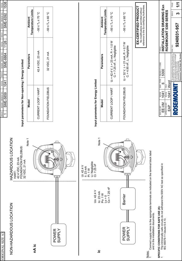
1. The intrinsically safe circuits do not withstand the 500V AC test as
specified in EN 60079-11:2012 clause 6.3.13.
2. Potential ignition hazards by impact or friction need to be considered
according to EN 60079-0:2018 clause 8.3 (for EPL Ga and EPL Gb),
and clause 8.4 (for EPL Da and EPL Db), when the transmitter
enclosure and antennas exposed to the exterior atmosphere of the
tank, is made with light metals containing aluminium or titanium.
The end user shall determine the suitability with regard to avoid
hazards from impact and friction.
3. Parts of the sensor probes, for type 5300, are non-conducting
material covering metal surfaces. The area of the non-conducting
part exceeds the maximum permissible areas for Group III according
to EN 60079-0: 2018 clause 7.4.3 Therefore, when the antenna is
used in a potentially explosive atmosphere group III, EPL Da,
appropriate measures must be taken to prevent electrostatic
discharge.
4. The painted transmitter housing is non-conducting and exceeds the
maximum permissible areas for Group III according to EN 60079-0:
2018 clause 7.4:3. Therefore, when the probe is used in a potentially
dust explosive atmosphere group III, appropriate measures must be
taken to prevent electrostatic discharge (i.e. only clean with a damp
cloth).
5. 1/2” NPT threads need to be sealed for dust and water ingress
protection, IP 66, IP 67 or “Ex t”. EPL Da or Db is required.
Ui Ii Pi Ci Li
Entity parameters 30 V 130 mA 1W 7.26 nF 0
HART
Entity parameters 30 V 300 mA 1.5 W 4.95 nF 0
Fieldbus
9.7.3 IA ATEX FISCO
Certificate Nemko 04ATEX1073X
Quick Start Guide 35Quick Start Guide January 2022
Standards EN 60079-0:2018, EN 60079-1:2014, EN
60079-11:2012, EN 60079-26:2015, EN 60079-31:2014
Markings II 1G Ex ia IIC T4 Ga (-55 °C ≤ Ta ≤+60 °C) or
II 1/2G Ex ia/ib IIC T4 Ga/Gb (-55 °C ≤ Ta ≤ +60 °C)
II 1D Ex ia IIIC T69 °C Da, (-50 °C ≤ Ta ≤ +60 °C)
II 1D Ex ia/ib IIIC T69°C Da/Db, (-50 °C ≤ Ta ≤ +60 °C)
Special Conditions for Safe Use (X):
1. The intrinsically safe circuits do not withstand the 500V AC test as
specified in EN 60079-11:2012 clause 6.3.13.
2. Potential ignition hazards by impact or friction need to be considered
according to EN 60079-0:2018 clause 8.3 (for EPL Ga and EPL Gb),
and clause 8.4 (for EPL Da and EPL Db), when the transmitter
enclosure and antennas exposed to the exterior atmosphere of the
tank, is made with light metals containing aluminium or titanium.
The end user shall determine the suitability with regard to avoid
hazards from impact and friction.
3. Parts of the sensor probes, for type 5300, are non-conducting
material covering metal surfaces. The area of the non-conducting
part exceeds the maximum permissible areas for Group III according
to EN 60079-0: 2018 clause 7.4.3 Therefore, when the antenna is
used in a potentially explosive atmosphere group III, EPL Da,
appropriate measures must be taken to prevent electrostatic
discharge.
4. The painted transmitter housing is non-conducting and exceeds the
maximum permissible areas for Group III according to EN 60079-0:
2018 clause 7.4:3.. Therefore, when the probe is used in a potentially
dust explosive atmosphere group III, appropriate measures must be
taken to prevent electrostatic discharge (i.e. only clean with a damp
cloth).
5. The Ex ia version of model 5300 FISCO device may be supplied by an
“Ex ib” FISCO power supply, when the power supply is certified with
three separate safety current limiting devices and voltage limitation
which meets the requirements for type Ex ia.
6. 1/2” NPT threads need to be sealed for dust and water ingress
protection, IP 66, IP 67 or “Ex t”. EPL Da or Db is required.
Ui Ii Pi Ci Li
FISCO parameters 17.5 V 380 mA 5.32 W 4.95 nFJanuary 2022 Quick Start Guide
9.7.4 N1 ATEX Type N
Certificate Nemko 10ATEX1072X
Standards EN 60079-0:2012+A11:2013, EN 60079-11:2012, EN
60079-15:2010, EN 60079-31:2014
Markings II 3G Ex nA ic IIC T4 Gc
II 3G Ex ic IIC T4 Gc
II 3D Ex tc IIIC T69 °C (FIELDBUS) /T79 °C (HART) Dc
-50 °C ≤ Ta ≤ +60 °C (FIELDBUS) /+70 °C (HART)
Special Conditions for Safe Use (X):
1. The transmitter circuits does not withstand 500V AC dielectric
strength test according to EN 60079-11 clause 6.3.13 due to earth
connected transient suppressing devices. Appropriate measures
have to be considered by installation.
Ui Ii Pi Ci Li
Safety parameters 42.4 V 23 mA 1W 7.25 nF Negligible
HART
Safety parameters 32 V 21 mA 0.7 W 4.95 nF Negligible
Fieldbus
9.8 International
9.8.1 E7 IECEx Flameproof
Certificate IECEx NEM 06.0001X
Standards IEC 60079-0:2017, IEC 60079-1:2014-06, IEC
60079-11:2011, IEC 60079-26:2014, IEC
60079-31:2013
Markings Ex db ia IIC T4 Ga/Gb
-55 °C ≤ Ta ≤ +60 °C (FIELDBUS) /+70 °C (HART)
Ex ta IIIC T69 °C (FIELDBUS) /T79 °C (HART) Da
-40 °C ≤ Ta ≤ +60 °C (FIELDBUS) /+70 °C (HART)
Um=250 VAC, IP66/IP67
Special Conditions for Safe Use (X):
1. Potential ignition hazards by impact or friction need to be considered
according to IEC 60079-0:2017 clause 8.3 (for EPL Ga and EPL Gb),
and clause 8.4 (for EPL Da and EPL Db), when the transmitter
enclosure and antennas exposed to the exterior atmosphere of the
Quick Start Guide 37Quick Start Guide January 2022
tank, is made with light metals containing aluminium or titanium.
The end user shall determine the suitability with regard to avoid
hazards from impact and friction.
2. Parts of the sensor probes for type 5300 are non-conducting material
covering metal surfaces and the area of the non-conducting part
exceeds the maximum permissible areas for Group III according to
IEC 60079-0: 2017 clause 7.4:3 Therefore, when the antenna is used
in a potentially explosive atmosphere group III, EPL Da, appropriate
measures must be taken to prevent electrostatic discharge.
3. The painted transmitter housing is non-conducting and exceeds the
maximum permissible areas for Group III according to IEC 60079-0:
2017 clause 7.4:3. Therefore, when the probe is used in a potentially
dust explosive atmosphere group III, appropriate measures must be
taken to prevent electrostatic discharge (i.e. only clean with a damp
cloth).
4. 1/2” NPT threads need to be sealed for dust and water ingress
protection, IP 66, IP 67 or “Ex t”. EPL Da or Db is required.
9.8.2 I7 IECEx Intrinsic Safety
Certificate IECEx NEM 06.0001X
Standards IEC 60079-0:2017, IEC 60079-1:2014-06, IEC
60079-11:2011, IEC 60079-26:2014, IEC
60079-31:2013
Markings Ex ia IIC T4 Ga
-55 °C ≤ Ta ≤ +60 °C (FIELDBUS) /+70 °C (HART)
Ex ia IIIC T69 °C/T79 °C Da
-50 °C ≤ Ta ≤ +60 °C (FIELDBUS) /+70 °C (HART)
Special Conditions for Safe Use (X):
1. The intrinsically safe circuits do not withstand the 500V AC test as
specified in IEC 60079-11 clause 6.3.13.
2. Potential ignition hazards by impact or friction need to be considered
according to IEC 60079-0:2017 clause 8.3 (for EPL Ga and EPL Gb),
and clause 8.4 (for EPL Da and EPL Db), when the transmitter
enclosure and antennas exposed to the exterior atmosphere of the
tank, is made with light metals containing aluminium or titanium.
The end user shall determine the suitability with regard to avoid
hazards from impact and friction.
3. Parts of the sensor probes for type 5300 are non-conducting material
covering metal surfaces and the area of the non-conducting part
exceeds the maximum permissible areas for Group III according to
38 Rosemount 5300 Level TransmitterJanuary 2022 Quick Start Guide
IEC 60079-0: 2017 clause 7.4:3 Therefore, when the antenna is used
in a potentially explosive atmosphere group III, EPL Da, appropriate
measures must be taken to prevent electrostatic discharge.
4. The painted transmitter housing is non-conducting and exceeds the
maximum permissible areas for Group III according to IEC 60079-0:
2017 clause 7.4:3. Therefore, when the probe is used in a potentially
dust explosive atmosphere group III, appropriate measures must be
taken to prevent electrostatic discharge (i.e. only clean with a damp
cloth).
5. 1/2” NPT threads need to be sealed for dust and water ingress
protection, IP 66, IP 67 or “Ex t”. EPL Da or Db is required.
Ui Ii Pi Ci Li
Entity parameters 30 V 130 mA 1W 0 µF Negligible
HART
Entity parameters 30 V 300 mA 1.5 W 4.95 nF Negligible
Fieldbus
9.8.3 IG IECEx FISCO
Certificate IECEx NEM 06.0001X
Standards IEC 60079-0:2017, IEC 60079-1:2014-06, IEC
60079-11:2011, IEC 60079-26:2014, IEC
60079-31:2013
Markings Ex ia IIC T4 Ga (-55 °C ≤ Ta ≤ +60 °C)
Ex ia/ib IIC T4 Ga/Gb (-55 °C ≤ Ta ≤ +60 °C)
Ex ia IIIC T69 °C Da (-50 °C ≤ Ta ≤ +60 °C)
Ex ia/ib IIIC T69 °C Da/Db (-50 °C ≤ Ta ≤ +60 °C)
Special Conditions for Safe Use (X):
1. The intrinsically safe circuits do not withstand the 500V AC test as
specified in IEC 60079-11 clause 6.3.13.
2. Potential ignition hazards by impact or friction need to be considered
according to IEC 60079-0:2017 clause 8.3 (for EPL Ga and EPL Gb),
and clause 8.4 (for EPL Da and EPL Db), when the transmitter
enclosure and antennas exposed to the exterior atmosphere of the
tank, is made with light metals containing aluminium or titanium.
The end user shall determine the suitability with regard to avoid
hazards from impact and friction.
3. Parts of the sensor probes for type 5300 are non-conducting material
covering metal surfaces and the area of the non-conducting part
Quick Start Guide 39Quick Start Guide January 2022
exceeds the maximum permissible areas for Group III according to
IEC 60079-0: 2017 clause 7.4:3 Therefore, when the antenna is used
in a potentially explosive atmosphere group III, EPL Da, appropriate
measures must be taken to prevent electrostatic discharge.
4. The painted transmitter housing is non-conducting and exceeds the
maximum permissible areas for Group III according to IEC 60079-0:
2017 clause 7.4:3. Therefore, when the probe is used in a potentially
dust explosive atmosphere group III, appropriate measures must be
taken to prevent electrostatic discharge (i.e. only clean with a damp
cloth).
5. The Ex ia version of model 5300 FISCO field device may be supplied
by an [Ex ib] FISCO power supply when the power supply is certified
with three separate safety current limiting devices and voltage
limitation which meets the requirements for type Ex ia.
6. ½” NPT threads need to be sealed for dust and water ingress
protection, IP 66, IP 67 or “Ex t”, EPL Da or Db is required.
Ui Ii Pi Ci Li
FISCO parameters 17.5 V 380 mA 5.32 W 4.95 nFJanuary 2022 Quick Start Guide
9.9 Brazil
9.9.1 E2 INMETRO Flameproof
Certificate UL-BR 17.0188X
Standards ABNT NBR IEC 60079-0:2013, ABNT NBR IEC
60079-1:2016, ABNT NBR IEC 60079-11:2013, ABNT
NBR IEC 60079-26:2016, ABNT NBR IEC 60079-31:2014
Markings Ex db ia IIC T4 Ga/Gb (-55 °C ≤ Tamb ≤ +60 °C /+70 °C)
Ex ta IIIC T69 °C/T79 °C Da (-40 °C ≤ Tamb ≤ +60 °C /+70
°C)
Um=250 Vac, IP66/67
Special Conditions for Safe Use (X):
1. See certificate for Specific Conditions.
9.9.2 I2 INMETRO Intrinsic Safety
Certificate Certificate: UL-BR 17.0188X
Standards ABNT NBR IEC 60079-0:2013 , ABNT NBR IEC
60079-11:2013, ABNT NBR IEC 60079-26:2016, ABNT
NBR IEC 60079-31:2014
Markings Ex ia IIC T4 Ga (- 55 °C ≤ Tamb ≤ +60 °C /+70 °C)
Ex ia IIIC T69 °C/T79 °C Da (- 50 °C ≤ Tamb ≤ +60 °C /+70
°C)
Special Conditions for Safe Use (X):
1. See certificate for Specific Conditions.
Ui Ii Pi Ci Li
Entity parameters 30 Vdc 130 mA 1.0 W 7.26 nF Negligible
HART
Entity parameters 30 Vdc 300 mA 1.5 W 4.95 nF Negligible
Fieldbus
9.9.3 IB INMETRO FISCO
Certificate UL-BR 17.0188X
Standards ABNT NBR IEC 60079-0:2013, ABNT NBR IEC
60079-11:2013, ABNT NBR IEC 60079-26:2016, ABNT
NBR IEC 60079-31:2014
Quick Start Guide 41Quick Start Guide January 2022
Markings Ex ia IIC T4 Ga (- 55 °C ≤ Tamb ≤ +60 °C)
Ex ia/ib IIC T4 Ga/Gb (- 55 °C ≤ Tamb ≤ +60 °C)
Ex ia IIIC T69 °C Da (- 50 °C ≤ Tamb ≤ +60 °C)
Ex ia/ib IIIC T69 °C Da/Db (- 50 °C ≤ Tamb ≤ +60 °C)
Special Conditions for Safe Use (X):
1. See certificate for Specific Conditions.
Ui Ii Pi Ci Li
FISCO parameters 17.5 Vdc 380 mA 5.32 W 4.95 nFJanuary 2022 Quick Start Guide
9.10.3 IC China FISCO
Certificate GYJ20.1621X
Standards GB 3836.1/2/4/20-2010, GB 12476.4/5-2013, GB
12476.1-2010
Markings Ex ia IIC T4 Ga (-55 °C ≤ Ta ≤ +60 °C)
Ex ia/ib IIC T4 Ga/Gb (-55 °C ≤ Ta ≤ +60 °C)
Ex iaD 20 T69 (-50 °C ≤ Ta ≤ +60 °C)
Ex iaD/ibD 20/21 T69 °C (-50 °C ≤ Ta ≤ +60 °C)
Special Conditions for Safe Use (X):
1. See certificate for Specific Conditions.
Ui Ii Pi Ci Li
FISCO parameters 17.5 V 380 mA 5.32 W 4.95 nFQuick Start Guide January 2022
9.11.1 EM Technical Regulations Customs Union (EAC) Flameproof
Certificate ЕАЭС RU C-SE.EX01.B.0086/19
Markings Ga/Gb Ex db ia IIC T4….T1 X, (-55 °C ≤ Ta ≤ +60 °C/+70
°C)
Ex ta IIIC T69 °C/T79 °C Da X (-40 °C ≤ Ta ≤ +60 °C/+70
°C)
Special Conditions for Safe Use (X):
1. See certificate for Specific Conditions.
9.11.2 IM Technical Regulations Customs Union (EAC) Intrinsic Safety
Certificate ЕАЭС RU C-SE.EX01.B.0086/19
Markings 0Ex ia IIC T4...T1 Ga X, (-55 °C ≤ Ta ≤ +60 °C/+70 °C)
Ex ia IIIC T69 °C/T79 °C Da X, (-50 °C ≤ Ta ≤ +60 °C/+70
°C)
Special Conditions for Safe Use (X):
1. See certificate for Specific Conditions.
Ui Ii Pi Ci Li
Entity parameters 30 V 130 mA 1W 7.26 nF 0 mH
HART
Entity parameters 30 V 300 mA 1.5 W 4.95 nF 0 mH
Fieldbus
9.11.3 IN Technical Regulations Customs Union (EAC) FISCO
Certificate ЕАЭС RU C-SE.EX01.B.0086/19
Markings 0Ex ia IIC T4...T1 Ga X, (-55 °C ≤ Ta ≤ +60 °C)
Ga/Gb Ex ia/ib IIC T4…T1 X, (-55 °C ≤ Ta ≤ +60 °C)
Ex ia IIIC T69 °C Da X, (-50 °C ≤ Ta ≤ +60 °C)
Ex ia/ib IIIC T69 °C Da/Db X, (-50 °C ≤ Ta ≤ +60 °C)
Special Conditions for Safe Use (X):
1. See certificate for Specific Conditions.
Ui Ii Pi Ci Li
FISCO parameters 17.5 V 380 mA 5.32 W 4.95 nF 0 mH
44 Rosemount 5300 Level TransmitterJanuary 2022 Quick Start Guide
9.12 Japan
9.12.1 E4 Flameproof
Certificate CML 17JPN1334X
Markings Ex db ia IIC T4 Ga/Gb (-55 °C ≤ Ta ≤ +60 °C/+70 °C)
Special Conditions for Safe Use (X):
1. See certificate for Specific Conditions.
9.13 Republic of Korea
9.13.1 EP Flameproof HART
Certificate KTL 15-KB4BO-0297X, 13-KB4BO-0019X
Markings Ex d ia IIC T4 Ga/Gb
Special Conditions for Safe Use (X):
1. See certificate for Specific Conditions.
9.13.2 EP Flameproof Fieldbus
Certificate KTL 12-KB4BO-0179X
Markings Ex d ia IIC T4
Special Conditions for Safe Use (X):
1. See certificate for Specific Conditions.
9.14 India
9.14.1 Flameproof, Intrinsically safe
Certificate P392482/1
Markings Ex db ia IIC T4 Ga /Gb
Ex ia IIC T4 Ga
Special Conditions for Safe Use (X):
1. See certificate for Specific Conditions.
Quick Start Guide 45Quick Start Guide January 2022
9.15 United Arab Emirates
9.15.1 Flame-proof
Certificate 20-11-28736/Q20-11-001012
Markings Same as IECEx (E7)
9.15.2 Intrinsic Safety
Certificate 20-11-28736/Q20-11-001012
Markings Same as IECEx (I7)
9.15.3 FISCO
Certificate 20-11-28736/Q20-11-001012
Markings Same as IECEx (IG)
9.15.4 Type N
Certificate 20-11-28736/Q20-11-001012
Markings Same as IECEx (N7)
9.16 Ukraine
9.16.1 Flameproof, Intrinsically Safe
Certificate UA.TR.047.C.0352-13
Markings 0 Ex ia IIC T4 X,
1 Ex d ia IIC T4 X
Special Conditions for Safe Use (X):
1. See certificate for Specific Conditions.
9.17 Uzbekistan
9.17.1 Safety (import)
Certificate UZ.SMT.01.342.2017121
9.18 Combinations
KA Combination of E1, E5 and E6
KB Combination of E1, E5 and E7
KC Combination of E1, E6 and E7
46 Rosemount 5300 Level TransmitterJanuary 2022 Quick Start Guide
KD Combination of E5, E6 and E7
KE Combination of I1, I5 and I6
KF Combination of I1, I5 and I7
KG Combination of I1, I6 and I7
KH Combination of I5, I6 and I7
KI Combination of IA, IE and IF
KJ Combination of IA, IE and IG
KK Combination of IA, IF and IG
KL Combination of IE, IF and IG
9.19 Additional certifications
9.19.1 SBS American Bureau of Shipping (ABS) Type Approval
Certificate 21-2136361-PDA
Intended Use For use on ABS Classed Vessels and Offshore Facilities in
accordance with ABS rules and International Standards.
Note
Housing material A, Aluminum, is not to be used on open decks.
9.19.2 SBV Bureau Veritas (BV) Type Approval
Certificate 22378_C0 BV
Requirements Bureau Veritas rules for classification of steel ships. EC
Code: 41SB
Application Class Notations: AUT-UMS, AUT-CCS, AUT-PORT and
AUT-IMS.
Note
Housing material A, Aluminum, is not to be used on open decks.
9.19.3 SDN Det Norske Veritas Germanischer Lloyd (DNV GL) Type Approval
Certificate TAA000020G
Intended Use DNV GL rules for classification – Ships, offshore units,
and high speed and light craft
Quick Start Guide 47Quick Start Guide January 2022
Table 9-1: Application
Location classes
Temperature D
Humidity B
Vibration A
EMC B
Enclosure C
Note
Housing material A, Aluminum, is not to be used on open decks.
9.19.4 SKR Korean Register (KR) Type Approval
Certificate CPH05152-AE001
Requirements Pt. 6, Ch. 2, Art. 301 of the Rules for Classification of
Steel Ships.
Note
Housing material A, Aluminum, is not to be used on open decks.
9.19.5 SLL Lloyds Register (LR) Type Approval
Certificate LR2002854TA
Application Marine applications for use in environmental categories
ENV1, ENV2, ENV3 and ENV5.
Note
Housing material A, Aluminum, is not to be used on open decks.
9.19.6 SNK Nippon Kaiji Kyokai (NK) Type Approval
Certificate TA20555M
Requirements Ch.7, Pt. 6, and Ch. 4, Pt. 7 of “Guidance for the
Approval and Type Approval of Materials and Equipment
for Marine Use” and the relevant Society’s Rules
Note
Housing material A, Aluminum, is not to be used on open decks.
9.19.7 SRS Russian Maritime Register of Shipping (RS) Type Approval
Certificate 21.10002.262
48 Rosemount 5300 Level TransmitterJanuary 2022 Quick Start Guide
Rules Part XV of the Rules for the Classification and
Construction of Sea-going Ships 2020, Part XIV of the
Rules for the Classification, Construction and Equipment
of Mobile Offshore Drilling Units (MODU) and Fixed
Offshore Platforms of (FOP), 2018 Part IV, section 12 of
the Rules for Technical Supervision During Construction
of ships and Manufacture of Materials and Products for
Ships, 2020.
Note
Housing material A, Aluminum, is not to be used on open decks.
9.19.8 U1 Overfill prevention
Certificate Z-65.16-476
Application TÜV tested and approved by DIBt for overfill prevention
according to the German WHG regulations.
9.19.9 J1 Canadian Registration Number (CRN)
Alberta (ABSA): 0F18507.2, British Columbia (TSBC): 0F6710.1, Manitoba
(ITS): 0H6938.4, New Brunswick: 0F1290.97, New Foundland and Labrador:
0F1290.90, Northwest Territories: 0F1290.9T, Nova Scotia: 0F1290.98,
Nunavut: 0F1290.9N, Ontario (TSSA): 0F19892.5, Prince Edward Island:
0F1290.9, Quebec (RdBdQ): 0F04826.6, Saskatchewan (TSASK): 0F1870.3,
Yukon: 0F1290.9Y
9.19.10 J8 EN Boiler (European Boiler Approval in accordance with EN
12952-11 and EN 12953-9)
Note
Suitable for use as a level sensor part of a limiting device in accordance with
EN 12952-11 and EN 12953-9.
9.19.11 QT Safety-certified to IEC 61508:2010 with certificate of FMEDA data
Certificate exida ROS 13-06-005 C001 R2.2
9.19.12 Suitable for intended use
Compliant with NAMUR NE 95, version 22.01.2013 “Basic Principles of
Homologation”
9.20 Pattern Approval
GOST Belarus
Certificate No. 10263
Quick Start Guide 49Quick Start Guide January 2022
GOST Kazakhstan
Certificate No. 15466
GOST Russia
Certificate SE.C.29.010.A No.51062/1
GOST Uzbekistan
Certificate 02.7101
9.21 Conduit plugs and adapters
IECEx Flameproof and Increased Safety
Certificate IECEX UL 18.0016X
Standards IEC60079-0:2011, IEC60079-1:2014, IEC60079-7:2015,
IEC60079-31:2014
Markings Ex db eb IIC Gb; Ex ta IIIC Da
ATEX Flameproof and Increased Safety
Certificate DEMKO 18 ATEX 1986X
Standards EN 60079-0:2012+A11:2013, EN 60079-1:2014, EN
60079-7:2015, EN 60079-31:2014
Markings II 2 G Ex db eb IIC Gb
II 1 D Ex ta IIIC Da
Table 9-2: Conduit Plug Thread Sizes
Thread Identification mark
M20x1.5-6g M20
½ - 14 NPT ½ NPT
Table 9-3: Thread Adapter Thread Sizes
Male thread Identification mark
M20 x 1.5 – 6g M20
½- 14 NPT ½ - 14 NPT
Female thread Identification mark
M20 x 1.5 – 6H M20
½ - 14 NPT ½ - 14 NPT
50 Rosemount 5300 Level TransmitterJanuary 2022 Quick Start Guide
Specific Conditions for Safe Use (X):
1. The Blanking Elements shall not be used with an adapter.
2. Only one adapter shall be used with any single cable entry on the
associated equipment.
3. It is the end user’s responsibility to ensure that the ingress protection
rating is maintained at the interface of the equipment and the
blanking element/adapter.
4. Suitability of the temperature of the devices is to be determined
during end-use with suitably rated equipment.
Quick Start Guide 51Quick Start Guide January 2022 9.22 Installation drawings Figure 9-1: 9240030-936 - System Control Drawing for Hazardous Location Installation of Intrinsically Safe FM Approved Apparatus 52 Rosemount 5300 Level Transmitter
January 2022                                                     Quick Start Guide

Figure 9-2: 9240030-937 - Installation Drawing for Hazardous Location
Installation of Intrinsically Safe CSA Approved Apparatus

Quick Start Guide                                                              53
Quick Start Guide                                                     January 2022

Figure 9-3: D9240030-938 - Installation Drawing for Hazardous Location
Installation of Intrinsically Safe ATEX and IECEx Approved Apparatus

54                                                 Rosemount 5300 Level Transmitter
January 2022                                         Quick Start Guide

Figure 9-4: 9240031-957 - Installation Drawing Exn

Quick Start Guide                                                  55
Quick Start Guide                                             January 2022

9.23      EU Declaration of Conformity
Figure 9-5: EU Declaration of Conformity

56                                         Rosemount 5300 Level Transmitter
January 2022        Quick Start Guide

Quick Start Guide                 57
Quick Start Guide                      January 2022

58                  Rosemount 5300 Level Transmitter
January 2022        Quick Start Guide

Quick Start Guide                 59
Quick Start Guide January 2022
9.24 China RoHS
List of Model Parts with China RoHS Concentration above MCVs
含有China RoHS管控物峐超彯㚨⣏㳻⹎旸ῤ的部件型号列表
Hazardous Substances / 有害物峐
Part Name Hexavalent Polybrominated Polybrominated
部件名称
Lead Mercury Cadmium
汞
Chromium biphenyls diphenyl ethers
摭 擱
භ௴撔 ከ⁏俼劗 ከ⁏俼劗慂(PBDE)
(Pb) (Hg) (Cd)
(Cr +6) (PBB)
Electronics
Assembly X O O O O O
䓝⫸乬ẞ
Housing
Assembly O O O O O O
壳体乬ẞ
This table is proposed in accordance with the provision of SJ/T11364
本表格系依据SJ/T11364的奬⭂侴⇞ἄį
O: Indicate that said hazardous substance in all of the homogeneous materials for this part is below the limit requirement
of GB/T 26572.
O: 意ᷢ宍悐ẞ䘬㚱⛯峐㛸㕁ᷕ宍㚱⭛䈑峐䘬⏓慷⛯ỶḶGB/T 26572所奬⭂䘬旸慷天㯪į
X: Indicate that said hazardous substance contained in at least one of the homogeneous materials used for this part is
above the limit requirement of GB/T 26572.
X: 意ᷢ⛐宍悐ẞἧ䓐䘬㚱⛯峐㛸㕁慴炻军⮹㚱ᶨ䰣⛯峐㛸㕁ᷕ宍㚱⭛䈑峐䘬⏓慷檀ḶGB/T 26572所奬⭂䘬旸慷天㯪į
60 Rosemount 5300 Level TransmitterJanuary 2022 Quick Start Guide Quick Start Guide 61
Quick Start Guide                      January 2022

62                  Rosemount 5300 Level Transmitter
January 2022        Quick Start Guide

Quick Start Guide                 63
*00825-0100-4530*
                                                   Quick Start Guide
                                           00825-0100-4530, Rev. HB
                                                       January 2022

For more information: www.emerson.com
©2022 Emerson. All rights reserved.

Emerson Terms and Conditions of Sale are
available upon request. The Emerson logo
is a trademark and service mark of
Emerson Electric Co. Rosemount is a mark
of one of the Emerson family of
companies. All other marks are the
property of their respective owners.
You can also read