QUERÉTARO LANDFILL-GAS-TO-ENERGY PROJECT - CLEAN DEVELOPMENT MECHANISM PROJECT DESIGN DOCUMENT
←
→
Page content transcription
If your browser does not render page correctly, please read the page content below
PROJECT DESIGN DOCUMENT FORM (CDM PDD) - Version 03.1.

CDM – Executive Board

                                                                      page 1

                        CLEAN DEVELOPMENT MECHANISM

                          PROJECT DESIGN DOCUMENT

    QUERÉTARO LANDFILL-GAS-TO-ENERGY PROJECT

                                       -

                                   Version 0

                             QUERÉTARO LANDFILL
                                  MEXICO

                                       -

                                   JUNE 2009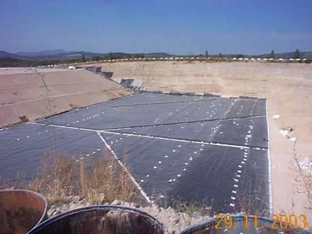
PROJECT DESIGN DOCUMENT FORM (CDM PDD) - Version 03.1.

CDM – Executive Board

                                                                            page 2

                        CLEAN DEVELOPMENT MECHANISM
                    PROJECT DESIGN DOCUMENT FORM (CDM-PDD)
                         Version 03 - in effect as of: 28 July 2006

                                            CONTENTS

     A.      General description of project activity

     B.      Application of a baseline and monitoring methodology

     C.      Duration of the project activity / crediting period

     D.      Environmental impacts

     E.      Stakeholders’ comments

                                                Annex

     Annex 1: Contact information on participants in the project activity

     Annex 2: Information regarding public funding

     Annex 3: Baseline information

     Annex 4: Monitoring plan

     Annex 5: Mass, energy and emission flow information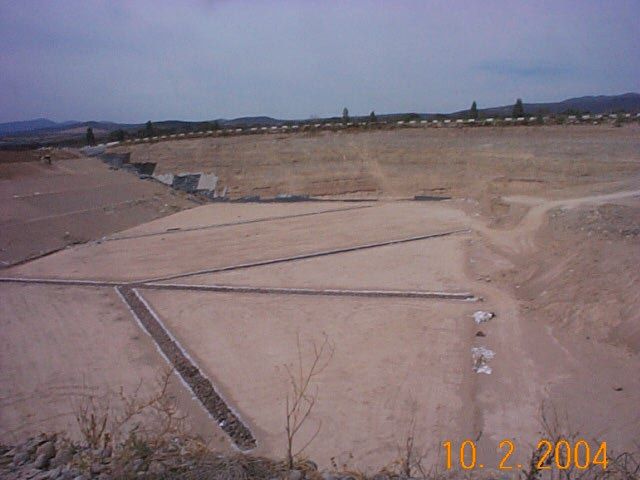
PROJECT DESIGN DOCUMENT FORM (CDM PDD) - Version 03.1.

 CDM – Executive Board

                                                                                              page 3

SECTION A. General description of project activity

A.1    Title of the project activity:
>>
Querétaro landfill-gas-to-energy project, version 0,
11/06/2009.

A.2.     Description of the project activity:
>>
The project involves landfill gas capture and energy recovery at the Querétaro municipal solid waste
landfill site in Santiago de Querétaro, capital of the State of Querétaro in Mexico. The Querétaro
landfill, used for the disposal of the waste generated by the municipality’s 735 000 inhabitants, started to
operate in February, 1996.

                     Figure 1: View of the gas wells at the Querétaro landfill site

Tecnología del Medio Ambiente de Querétaro SA, PI de CV (TMQ), a joint company between Eolicia
Biogas Borealia Energy, S.L. (EBB Energy – 49%), a renewable energy company and Proactiva Medio
Ambiente México S.A. de CV (51%), the landfill operator, has been selected by the municipality of
Querétaro to develop a CDM project to reduce the greenhouse gas emissions from the landfill site.

Proactiva Medio Ambiente is a Spanish company headquartered in Madrid and a leading environmental
services provider in Latin America, offering a spectrum of services from waste management to water
and wastewater services. Proactiva Medio Ambiente was created in 1996 when its two 50% shareholders
Fomento de Construcciones y Contratas, S.A. (FCC), and Veolia Environnement decided to join forces
to establish their environmental services activities in Latin America. Both companies are international
references.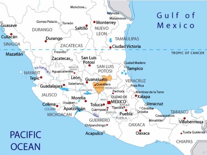
PROJECT DESIGN DOCUMENT FORM (CDM PDD) - Version 03.1.

 CDM – Executive Board

                                                                                                page 4

Present in 6 countries in Latin America, Proactiva Medio Ambiente operates 15 landfills, with 7 located
in Mexico, that treated close to 6.5 million tonnes of waste in 2007. All of these landfills are equipped
with safe and modern systems for treatment and final disposal of solid waste: liner systems, storm water
drainage, leachate collection and treatment, and best practices for passive landfill gas venting and
monitoring of both surface and groundwater.

EBB energy, is headquartered in Spain and is specialized in the promotion, design, consultancy and
maintenance of renewable energy projects. Composed by 3 companies Eolicia S.L. (33.33%), Biogas
Fuel Cell S.A (33.33%) and Borealia Ingeniería S.L.(33.33%), they joined forces and skills to develop
more than 100 projects of collection and combustion of landfill gas leading to the installation of a
renewable energy capacity of 35MW.

The Querétaro site belongs to the most advanced landfills in Mexico incorporating the environmental
controls and technical elements noted in the paragraph above.

The on-site infrastructure also includes:
       -        A recycling centre where a portion of the incoming waste is recycled prior to landfilling
       -        A weighbridge used to weigh all incoming waste
       -        An office, employee facilities, and a workshop

Proactiva Medio Ambiente won the concession in 1995 and started operating the site in 1996. The
landfill accepts an average of 250,000 tonnes of household waste per year.

The current practice onsite, or the scenario in place prior to the implementation of the project activity, is
the passive venting of the landfill gas, where a few of the passive vents are lit from time to time to burn
escaping gas. The baseline scenario is the same as the scenario existing prior to the implementation of
the project activity, or the current scenario.

Purpose of the project activity:
The project´s objective is the active collection of the landfill gas currently emitted by the landfill via a
centralised pipework system. Controlled destruction will be secured by an enclosed flare in a first phase,
then by energy recovery via a landfill gas engine facility and a leachate evaporator, if the landfill gas
quality and quantity are found to be sufficient. Landfill gas combustion will thereby reduce greenhouse
gas emissions into the atmosphere.

TMQ will be responsible for all investments and operating costs necessary to perform the project within
the Clean Development Mechanism.

Project activity:
The project will be developed following a phased approach.

The first phase aims at maximising capture of landfill gas on site via the installation of:
   • enhanced landfill gas extraction equipment to collect gas from existing and future disposal areas
   • flaring equipment for the destruction of landfill gas (methane)

During this phase, technical information on the landfill gas (both in terms of quality and quantity) and
feed-back from operational experience regarding the stability of the landfill gas system will be collected
for the evaluation of the second phase.

The second phase aims at utilizing the landfill gas for the production of electricity and subsequent export
to the national grid. In parallel the landfill gas will be used for onsite treatment of leachate (evaporation)
and will further improve the efficiency of the landfill gas collection. This second phase will be initiated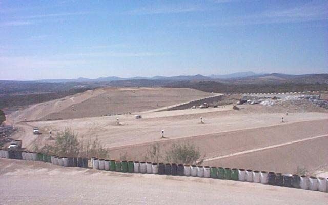
PROJECT DESIGN DOCUMENT FORM (CDM PDD) - Version 03.1.

 CDM – Executive Board

                                                                                            page 5

only if the technical and economical barriers can be overcome (e.g. a contractual agreement for the sale
of electricity).

Both phases of the project will contribute to fight global warming and climate change by:
   • reducing fugitive emissions of methane generated by anaerobic waste decomposition, a
       greenhouse gas with 21 times the global warming effect of CO2,
   • generating heat and/or electricity using landfill gas, thus reducing greenhouse gas emissions
       from fossil fuels ordinarily used in the electricity production in Mexico.

Included in the project boundary are CH4 emissions from landfill gas (baseline) and CO2 emissions from
electricity consumption (both in the baseline and project activity).

The project contributes to sustainable development in different ways, as it is demonstrated below.

Environmental benefits:
The CDM project activity at the Querétaro landfill will lead to environmental improvements by
providing infrastructure such as a safe and environmentally sound waste treatment facility and by
addressing the global challenge of climate change.

The combustion of the collected landfill gas in a flare or an engine does not only destroy methane but
also other harmful compounds in the landfill gas such as ammonia and volatile organic compounds.

More precisely, the project will prevent the following additional risks associated with landfill gas at
uncontrolled landfills:
   • Risk of explosion
   • Risk of fire
   • Nuisances caused by odours
   • Potential atmospheric pollution by landfill gas compounds
   • Damage to vegetation by asphyxia

Technology transfer:
Besides improving the overall management of the landfill, the Querétaro project will:
   • support efforts aimed at disseminating technology and operational experience gained on-site for
        use throughout the region or country,
   • introduce a renewable energy generation system, and
   • contribute to sustainable development technologies through investment.

Social benefits:
The project will also support local economic development through technology transfer and the creation
of local employment opportunities.

Indeed, the implementation of the project and its operation over 21 years will create direct and indirect
jobs. Staff will be required to operate and maintain the equipment (landfill gas network, flare, leachate
treatment unit, landfill gas engines). The staff will be trained in advanced landfill operation techniques
in order to optimise the landfill gas collection system on a daily basis. In addition, contractors and
labourers will be needed for the construction and external control of the project.

It shall be noted that the revenues generated by the CDM project are shared with the local municipality
of Santiago de Querétaro. This source of revenue will be used to implement sustainable development
projects to the benefit of the community.

To summarize the benefits mentioned above, this CDM project activity would lead to a net improvement
of economic and social conditions in the area surrounding the Querétaro site. It would also encourage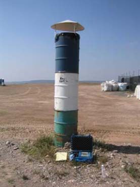
PROJECT DESIGN DOCUMENT FORM (CDM PDD) - Version 03.1.

 CDM – Executive Board

                                                                                               page 6

the development of alternative and sustainable energy sources, and contribute to energy independence
by exploiting an otherwise untapped natural resource.

Thus, taking the social, economic, environmental and technological benefits of the project activity into
account, the project participants TMQ, Proactiva Medio Ambiente, EBB Energy and Veolia Propreté are
convinced of the positive long-term contribution of this CDM project to sustainable development in the
area.

A.3.    Project participants:
>>
Project participants are named in the table below. For full contact details, please, refer to Annex 1 of this
document.

 Name of Party involved (*) Private and/or public entity(ies), project Kindly indicate if the party
 ((host) indicates a host party) participant (*)                        involved wishes to be
                                 (as applicable)                        considered as a project
                                                                        participant (Yes/No)
 Mexico (Host Country)           - Tecnología del Medio Ambiente de No
                                 Querétaro SA, PI de CV
                                 - Proactiva Medio Ambiente - México
                                 S.A. de CV
                                 - Eolicia Biogás Borealia Energy, S.L.
                                 - Eolicia, S.L.
                                 - Proactiva Medio Ambiente S.A
                                 - Veolia Propreté
                                 - Borealia Ingeniería, S.L.
                                 - Biogas Fuel Cell, S.A.

  (*) In accordance with the CDM modalities and procedures, at the time of making the CDM-PDD
 public at the stage of validation, a Party involved may or may not have provided its approval. At the
 time of requesting registration, the approval by the Party(ies) involved is required.

A.4.     Technical description of the project activity:

         A.4.1. Location of the project activity:

                 A.4.1.1.         Host Party(ies):
>>
Mexico

                 A.4.1.2.         Region/State/Province etc.:
>>
Querétaro

                 A.4.1.3.         City/Town/Community etc:
>>
Santiago de Querétaro
PROJECT DESIGN DOCUMENT FORM (CDM PDD) - Version 03.1.
CDM – Executive Board
page 7
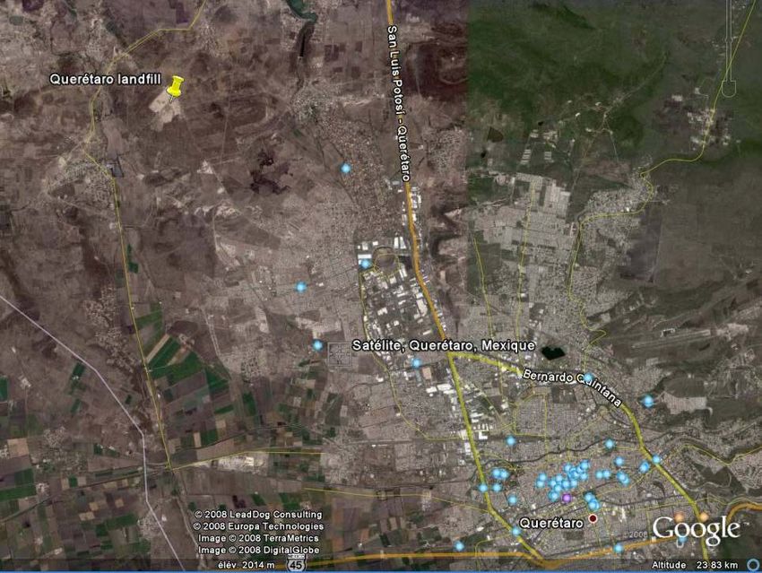
A.4.1.4. Detail of physical location, including information allowing the unique identification
of this project activity (maximum one page):
>>
The landfill associated with the project activity is located in the municipality of Santiago de Querétaro,
approximately 200 km northwest of Mexico City. The site is accessed at kilometer 5.5 on the road of
Satélite-Mompani, canyon Miguelote, at the following coordinates: 20°40'36.82"N - 100°29'26.96"O.
The surface area of the facility is of 20 ha of which 15 ha are dedicated to the landfilling of waste.
Figure 2: Localisation maps of Querétaro landfillPROJECT DESIGN DOCUMENT FORM (CDM PDD) - Version 03.1.
CDM – Executive Board
page 8
A.4.2. Category(ies) of project activity:
>>
Waste handling and disposal (Sector 13)
Energy industries: renewable and non renewable sources (Sector 1)
A.4.3. Technology to be employed by the project activity:
>>
Scenario existing prior to the project activity’s implementation:
As previously explained, this scenario is the same as the baseline scenario.
The Querétaro landfill consists of 3 cells. To date, more than 2.6 millions of tonnes of waste have been
deposited in Cells 1&2. Cell 3 will begin to accept waste when Cells 1&2 have reached their final
elevation, which is expected in 2007. An active gas collection system will first be implemented in Cell
1&2. Figure 3 below shows the landfill gas collection system’s conceptual layout for Cells 1&2.
Figure 3: Conceptual design of landfill gas collection system of the Querétaro landfill
The gas collection system will be extended to Cell 3 as landfilling progresses. Cell 3 will then be
connected to the system shown above to create a full ring main collector around the site and optimize
landfill gas collection.
The waste is placed in a controlled manner in dedicated cells within the landfill. Once the cells reach
their final elevation, a soil cover consisting of clay and topsoil is placed over the completed areas.
The construction of the cells consists of excavating the existing soil in accordance with the approved
grading plan to an average depth of 6 meters below the existing floor of the former mining site.
The nature of the soil provides a natural permeability of 10-7 m / second. A composite liner consisting of
a compacted clay liner overlaying a geomembrane liner is then installed. A drainage gravel layer and
piping is installed above the liner. The collected leachate is conveyed to a lined evaporation pond.PROJECT DESIGN DOCUMENT FORM (CDM PDD) - Version 03.1.
CDM – Executive Board
page 9
Equipment and systems in operation prior to the project activity, or the current practice:
39 passive vents are installed in the cells 1 and 2, some of which are fitted with rudimentary passive
flares, which are occasionally ignited. These wells have been designed and built to prevent methane
accumulation and limit risks of fire and explosion. The combustion process at a well head cannot be
controlled and for various reasons leads to a low combustion efficiency: flame temperature, heat losses,
retention time, etc…1
Activities, measures, and equipment being implemented within the project activity:
The project activity’s objective is to maximize both capture and recovery, and destruction of landfill gas
on the site. This will be reached via the installation of active landfill gas extraction equipment covering
all existing and future disposal areas. This equipment will be connected to an enclosed flare for the
controlled destruction of landfill gas, particularly methane, and in a second phase to a leachate
evaporator and a generator to produce electricity. Each of the landfill’s 3 cells will be equipped with
landfill gas collection systems.
Figure 4: Passive vent at the Querétaro landfill
Figure 5: Cell preparation at the Querétaro landfill
1
http://www.environment-agency.gov.uk/commondata/acrobat/lfg_flaring_guidance_1101730.pdfPROJECT DESIGN DOCUMENT FORM (CDM PDD) - Version 03.1.
CDM – Executive Board
page 10
Cells 1&2: Thirty-nine (39) passive vents have been installed in these cells, where vented landfill gas is
occasionally flared. Where possible, the existing gas wells will be used in the active collection system.
However, their well heads will be modified in order to improve the air-tightness of the system and to
connect the wells to the piping network. To complete the system, additional landfill gas wells will be
drilled into the waste in order to maximize the capture rate and reduce fugitive emissions of methane.
Cell 3: The gas collection system in Cell 3 will be designed in order to optimise the landfill gas
collection. Wells will be installed as landfilling progresses to allow for early collection of gas. Once the
cell is completed, additional wells may be drilled to complete the gas collection system.
Below is a brief summary of the equipment and technology proposed for this project:
Vertical wells
Vertical wells will be installed during filling. These cylindrical wells have a diameter of 50 cm and are
backfilled with stone and mounted as landfilling progresses. They consist of 150 mm HDPE perforated
pipes surrounded by non-calcareous gravel.
In order to complete the system, vertical wells may be drilled into the landfill once cells reach their final
elevation. The drilled vertical wells consist of a pipe perforated in its lower part, placed in a drilled
borehole in the waste, backfilled with gravel and sealed at the surface.
All well and drain types will be equipped with wellheads that enable the monitoring of the gas flow and
its quality. Also valves are provided to allow the adjustment of the vacuum at each well.
Leachate pumping systems
In some cases, leachate can prevent proper collection of landfill gas. Therefore, leachate collection will
be improved by enhancing the quality of the drainage layer and, if necessary, by installing submersible
leachate pumps in the landfill gas extraction wells. Pumping of the accumulated leachate will enhance
the efficiency of landfill gas collection systems.
Collection piping
A high-density polyethylene (HDPE) collection piping system will be installed to convey the landfill gas
from the well network to the blower and flare station, leachate evaporator or engine. The collection
system will be designed in order to minimise the low points which could disturb or prevent the gas
collection (due to condensate blockages). The system will be sized in order to avoid pressure losses due
to landfill gas friction by minimizing the velocity of the gas within the collection system.
The landfill gas combustion system consists of the following equipment:
Blower
A blower will be used to create the required vacuum in the collection network to extract the landfill gas.
The number of blowers will be adjusted in function of the quality and quantity of gas collected
throughout the life of the project.
High temperature enclosed flare
The project entails the installation of a flaring unit for the destruction of the captured landfill gas. The
flare will be enclosed and will provide a retention time above 0.3 seconds. The flare will be temperature
controlled, and maintain high temperatures in order to ensure a methane destruction rate beyond 97%.
Leachate treatment facility (evaporator)
As outlined in A.2. a leachate treatment facility will be installed if the results of the first phase in terms
of gas quality, quantity and stability are conclusive and if leachate treatment capacity has to be
increased. Leachate will thereby be evaporated in a specially designed device which uses the collected
landfill gas as source of energy and concentrates the leachate to 5% of its original volume.PROJECT DESIGN DOCUMENT FORM (CDM PDD) - Version 03.1.
CDM – Executive Board
page 11
Landfill gas engine facility
Also conditioned to the technical and economical evaluation in the first phase, up to two 1MW
reciprocating engines will be installed at the Querétaro landfill site in order to convert the landfill gas
into electricity. Each of these units will be containerized and of proven technology offering a high
efficiency and a remote control system. The engines will be specifically designed to operate within a
broad range of gas qualities and combustion will be controlled by a dedicated computerized system in
order to improve efficiency. A gas preparation unit will be designed according to the needs of the
measured landfill gas quality. This may consist of a moisture removal unit and/or an active charcoal
treatment.
Controls & Instrumentation
The flare will be equipped with automatic safety and monitoring controls to allow the proper
combustion of landfill gas.
Extensive instrumentation, monitoring and recording equipment will be installed to monitor landfill gas
quality, quantity and combustion quality, in accordance with the approved monitoring plan. These
parameters will provide adequate information on the performance of the equipment.
The project activity’s emission sources, energy flows and mass flows are described in Annex 5.
By implementing these technologies at Querétaro Landfill, TMQ, in partnership with Proactiva, EBB
Energy and Veolia Propreté, transfer their expertise and experience of these systems to the local team
that installs and operates them. Numerous training programs will be provided to our local staff.
Technical support is always available to help resolve difficulties.
A.4.4. Estimated amount of emission reductions over the chosen crediting period:
>>
The total estimated emission reductions to be realised 493,549 tCO2e over the first crediting period
starting December 1st, 2009, ending November 30th 2017, included. Expected emission reductions are in
the table below:PROJECT DESIGN DOCUMENT FORM (CDM PDD) - Version 03.1.
CDM – Executive Board
page 12
Annual estimation
of emission
Year
reductions in tonne
of CO2e
2009 1 months 4,895
2010 12 months 68,604
2011 12 months 73,437
2012 12 months 78,533
2013 12 months 74,174
2014 12 months 70,102
2015 12 months 66,296
2016 11 months 57,508
Total estimated reductions (tonnes
of CO2e) 493,549
Total number of crediting years 7 years
Annual average over the crediting
period of estimated reductions 70,507
(tonnes of CO2e)
Table 1: Annual estimation of emission reductions in tonnes of CO2e for the first crediting period
A.4.5. Public funding of the project activity:
>>
None
SECTION B. Application of a baseline and monitoring methodology
B.1. Title and reference of the approved baseline and monitoring methodology applied to the
project activity:
>>
The “Consolidated baseline methodology for landfill gas project activities” – ACM0001 / Version 11.
will be used in conjunction with the “Consolidated monitoring methodology for landfill gas project
activities” – ACM0001 / Version 11.
For the electricity generation component of the project, the AMS.I.D “Grid connected renewable
electricity generation / Version 13” will be utilised.
The following tools will be also used:
• “Tool for the demonstration and assessment of additionality” Version 05.2,
• “Tool to determine project emissions from flaring gases containing methane” Version 1,
• “Tool to calculate baseline, project and/or leakage emissions from electricity consumption”
Version 01,
• “Tool to determine methane emissions avoided from disposal of waste at a solid waste disposal
site” Version 04
• “Tool to calculate the emission factor for an electricity system” Version 01.1PROJECT DESIGN DOCUMENT FORM (CDM PDD) - Version 03.1.
CDM – Executive Board
page 13
B.2. Justification of the choice of the methodology and why it is applicable to the project
activity:
>>
The methodology ACM0001 / Version 11 allows for the development of projects falling under three
project options:
a) Landfill projects where the captured gas is simply flared;
b) The captured gas is used to produce energy (e.g. electricity/thermal energy). Emission
reductions can be claimed for thermal energy generation, only if the LFG displaces use of fossil
fuel either in a boiler or in an air heater. For claiming emission reductions for other thermal
energy equipment (e.g. kiln), project proponents may submit a revision to this methodology;
c) The captured gas is used to supply consumers through the natural gas distribution network. If
emission reductions are claimed for displacing natural gas, the project activity may use
approved methodology AM00053.
The proposed project activity is based on two activities, that both allow the reduction of greenhouse gas
emissions:
• the collection and combustion of landfill gas, preventing methane emissions to the atmosphere,
• the generation of heat for on-site use and the generation and supply of renewable electricity to
the grid, allowing the displacement of electricity that would otherwise have been generated by
regional power plants.
The project therefore fulfils the conditions of option (a) and (b) above (i.e., the captured landfill gas is
flared or used to produce energy), and the approved methodology ACM0001 / Version 11 will be used
in conjunction with its approved monitoring methodology and the tools that it refers to (cf. B.1).
The AMS.I.D “Grid connected renewable electricity generation / Version 13” is applicable since the
Projkect Participant intends to develop in a second phase a landfill gas generation unit of a capacity
inferior at 15MW. The installation is not a retrofit, a capacity addition or a replacement.
The use of the “Tool for the demonstration and assessment of additionality” - Version 05.2 is mandatory
for all projects that use methodology ACM0001.
The “Tool to determine project emissions from flaring gases containing methane” is applicable to the
flaring of residual gas streams derived from the decomposition of organic matter.
No other gas, except air, is added ito the residual gas stream. Landfill gas is mainly composed of
methane, carbon dioxide and oxygen. Only trace amounts of volatile organic compound can be found in
the landfill gas. The project activity is fulfilling the applicability criteria of the tool.
The “Tool to calculate baseline, project and/or leakage emissions from electricity consumption” is
applicable and has been used within the PDD to account for the project emissions associated with
electricity consumption. The project activity matches the applicability criteria defined in the scenario A:
The consumed electricity is either supplied by the on-site landfill gas electricity generator, or purchased
from the grid. The landfill gas engine is connected to the grid so it is not a captive power source.
“Tool to calculate project or leakage CO2 emissions from fossil fuel consumption” Version 02, refered
in the methodology has not been used since no fossil fuel will be consumed as part of the project
activity.
The “Tool to determine methane emissions avoided from disposal of waste at a solid waste disposal site”
is used to calculate baseline emissions of methane from non hazardous waste disposed of at landfill sitesPROJECT DESIGN DOCUMENT FORM (CDM PDD) - Version 03.1.
CDM – Executive Board
page 14
that are clearly identifiable. This is the case of the Querétaro landfill-gas-to-energy project. The tool is
therefore applicable.
The “Tool to calculate the emission factor for an electricity system” determines the CO2 emission factor
for the displacement of electricity generated by power plants in an electricity system. The Querétaro
project will generate electricity from landfill gas and thereby displaces electricity from the grid. This
tool is therefore applicable to the project.
B.3. Description of the sources and gases included in the project boundary
>>
According to its definition, the project boundary shall encompass all anthropogenic emissions by
sources of greenhouse gases under the control of the project participants that are significant and
reasonably attributable to the CDM project activity.
ACM0001 / Version 11 states that the project boundary is the site of the project activity where the gas is
captured and destroyed/used. In addition, since the renewable electricity exported by the project would
have been generated by power generation sources connected to the grid, the project boundary includes
all these power generation sources.
Source Gas Included? Justification / Explanation
CO2 emissions from the decomposition of organic waste are
Emissions from CO2 No
not accounted for
decomposition of
CH4 Yes The major source of emissions in the baseline
waste at the
N2O emissions are small compared to CH4 emissions from
landfill site N2O No
landfills. Exclusion of this gas is conservative
Baseline
CO2 Yes
Emissions from Emissions from the electricity production that would, in the
electricity CH4 No absence of the project activity, have been generated by the
consumption off-site power plants connected to the grid.
N2O No
Emissions from CO2 No
thermal energy CH4 No No thermal energy is used in the baseline
generation N2O No
On-site fossil fuel CO2 No
consumption due CH4 No
to the project
No fossil fuel is used as part of the project activity
activity other than
Project Activity
N2O No
for electricity
generation
Indirect emissions associated with the electricity consumed
CO2 Yes
from the grid for the project activity.
Emissions from
Excluded for simplification. This emission source is
on-site electricity CH4 No
assumed to be very small.
use
Excluded for simplification. This emission source is
N2O No
assumed to be very small.
The flowchart in Annex 5 shows the project boundary.
Fugitive emissions of landfill gas, and non-combusted landfill gas are excluded both from the baseline
and from the project activity, since these emissions exist and will exist despite the implementation of the
project activity.PROJECT DESIGN DOCUMENT FORM (CDM PDD) - Version 03.1.
CDM – Executive Board
page 15
B.4. Description of how the baseline scenario is identified and description of the identified
baseline scenario:
>>
The baseline scenario has been identified among alternative scenarios, after reviewing:
• the current practice of the waste management sector in Mexico,
• the legal and contractual obligations (existing and forthcoming), and
• the current practice on-site.
The Querétaro landfill belongs to the best managed landfills in Mexico, where venting of landfill gas
into the atmosphere with occasional passive flaring is common practice. In the absence of the project
activity, the current practice will be continued, defining the baseline scenario.
For further details regarding the baseline scenario, please see the demonstration of additionality in B.5.
B.5. Description of how the anthropogenic emissions of GHG by sources are reduced below
those that would have occurred in the absence of the registered CDM project activity (assessment
and demonstration of additionality):
>>
The installation of enhanced collection and flaring equipment, and in a second phase, the potential
installation of the leachate treatment equipment, landfill gas engines and associated equipment, will
require increased investment as well as increased operation and maintenance costs. The revenues
obtained from the sale of electricity to the grid are low compared to the investments. Only the expected
revenue to be generated by the sale of CERs offers an economic incentive to the project participants to
implement the project activity.
The following steps describe the approach used to assess the project’s additionality, given in
methodology ACM0001 / Version 11, and in “Tool for the demonstration and assessment of
additionality” – Version 05.2.
Procedure for the selection of the most plausible baseline scenario (Step 1 through 5):
Step 1: Identification of alternatives to the project activity consistent with current laws and
regulations
Sub-step 1a: Define alternatives to the project activity
As stated in the “Tool for demonstration and assessment of additionality” - Version 05.2, the alternatives
to the landfill gas, heat and the electricity components of the proposed project activity are considered.
The identified alternatives are listed below.
Alternatives to the landfill gas component of the project activity:
• LFG 1: Implementation of landfill gas collection network, flaring system, landfill gas engine,
and leachate evaporator without the CDM revenue
• LFG 2: Pursuance of actual site practice
• LFG 3: Implementation of a landfill gas collection and flaring system without energy recovery
Alternatives to the power generation component (landfill gas engine):
• P1: Power generated from landfill gas undertaken without being registered as CDM project
activity.
• P2: Utilisation of an existing or construction of a new on-site or off-site fossil fuel fired
cogeneration plantPROJECT DESIGN DOCUMENT FORM (CDM PDD) - Version 03.1.
CDM – Executive Board
page 16
• P3: Utilisation of an existing or construction of a new on-site or off-site renewable based
cogeneration plant
• P4: Utilisation of an existing or construction of a new on-site or off-site fossil fuel fired captive
power plant
• P5: Utilisation of an existing or construction of a new on-site or off-site renewable based captive
power plant
• P6: Existing and/or new grid connected power plants
Alternatives to the heat generation component (evaporator):
• H1: Heat generated from landfill gas undertaken without being registered as CDM project
activity
• H2: Existing or construction of a new on-site or off-site fossil fuel fired cogeneration plant.
• H3. Existing or construction of a new on-site or off-site renewable based cogeneration plant
• H4: Existing or new construction of on-site or off-site fossil fuel based boilers
• H5: Existing or new construction of on-site or off-site renewable energy based boilers
• H6: Any other sources such as district heat, and
• H7. Other heat generation technologies (e.g heat pumps or solar energy)
• H8. Continuation of the current practice: leachate is treated through an evaporation pond and
then recirculated into the landfill
Sub-step 1b: Consistency with mandatory laws and regulations
In Mexico, the only regulation concerning waste disposal is the NOM-083-SENARMAT-2003 which
defines the specifications for environmental protection for municipal and special solid waste. It defines
guidelines for the construction and operation of landfills, including recommendations for collection,
utilisation and/or flaring of the landfill gas. These guidelines do not define a minimum amount of
landfill gas to be collected, used or flared.
NOM-083-SEMARNAT-2003 has not been enforced in Mexico since its adoption in 2004. NOM-083 is
a federal law, and the States must adopt it before it can be enforced regionally. So far, no state has
adopted NOM-083-SEMARNAT-2003. Even the previous norm, NOM-083-SERMANAT-1996
recommending active venting of LFG for safety reasons, was not enforced.
In Mexico, waste management services are the responsibility of the municipalities, but in most cases,
these do not have the financial, technical or administrative resources to implement a controlled waste
management system. There is no indication that the waste management practice will change in the
coming years.
Concerning Querétaro landfill, there is no obligation to collect and/or flare the landfill gas within the
concession contract with the municipality of Santiago de Querétaro, which means that there is no
obligation to modify the current practice on-site.
As a consequence, no additional environmental investment is required by law or mandated by the
contract, and nothing prevents the continuation of the current scenario at Querétaro landfill site. Without
the revenue generated by the sale of CERs, the situation would stay the same since there is no expected
commercial use of landfill gas nor any forthcoming enforcement of laws or policies to initiate
investment in enhanced gas collection, extraction, flaring, or landfill gas utilisation systems.
The common practice in Mexico is, at best, the passive venting of landfill gas with occasional flaring,
and all the alternatives listed above are in compliance with the applicable legal and regulatory
requirements.PROJECT DESIGN DOCUMENT FORM (CDM PDD) - Version 03.1.
CDM – Executive Board
page 17
Step 2: Identify the fuel for the baseline choice of energy source taking into account the national
and/or sector policies as applicable.
The project activity will produce heat for onsite use and renewable electricity to supply the Mexican
grid. Therefore, the baseline source of energy is the electricity produced by power plants connected to
the grid. Close to 80% of the electricity produced in Mexico is fossil-fuel based. Given the abundant
resources the country has in hydrocarbons, the importance of fossil fuels in the national electricity
production is not likely to diminish significantly in the coming decade.
Step 3 and/or 4: Investment and/or barrier analysis
Alternative LFG 1: Implementation of landfill gas collection and flaring systems, where part of the
landfill gas is used to produce energy, or the project scenario, without the CDM revenue
This alternative involves redesigning the actual gas collection system, extending it to the rest of the site,
and connecting it to a vacuum substation, in order to feed a high-efficiency enclosed flare. If the quality,
quantity and stability of landfill gas are deemed sufficient, a treatment unit that uses landfill gas to
evaporate leachate will be installed in a second phase. In case a commercial agreement can be secured, a
reciprocating engine facility may as well be installed at that point. In this case, the electricity produced
will be sold into the national grid. Without considering the CDM revenue, the realization of this
alternative is unlikely. The system represents a significant investment and the revenue from the sale of
electricity alone will not be sufficient for the project to be viable. In order to demonstrate the non-
financial feasibility of the project, the substeps from the “Tool for the demonstration and assessment of
additionality” have been used.
Sub-step 2a: Determine appropriate analysis method from the “Tool for the demonstration
and assessment of additionality” – Version 05.2
Considering the potential revenue from the generation and sale of electricity to the grid, option III,
benchmark analysis, will be used.
Sub-step 2b, Option iii: Apply benchmark analysis
As defined within the “Tool for demonstration and assessment of the additionality”, if the alternative
generates financial or economic benefits other than CDM related income option II or III of Sub-step 2b
shall be used. Option III has been used.
The financial analysis details are presented in appendix 3.
This financial analysis demonstrates that the IRR of this alternative is -2.84% .
Sub-step 2c: Calculation and comparison of financial indicators
The result of the cost analysis shows that the project does not meet the minimum IRR used in the
industry: the IRR is largely below the bench indicators provided by Bloomberg. The financial indicator
for Mexico is published by Bloomberg Finance L.D. The indicator consists of the capital cost in Mexico
and the country risk premium. The cost of money without risk is set at 7.49%. The risk premium is also
defined by Bloomberg at 8.57%. Consequently, the set expected return of the capital by the market is
16.06%.
IRR
Project without CDM revenues -2.84%
Project with CDM revenues 18.31%PROJECT DESIGN DOCUMENT FORM (CDM PDD) - Version 03.1.
CDM – Executive Board
page 18
The values above show that the project activity is not a likely scenario. Only the revenue associated with
the sale of the CERs make the project feasible.
Sub-step 2d: Sensitivity analysis
A sensitivity analysis was also conducted by altering key parameters: the investment cost, the operating
and maintenance cost and the revenues. The results of the study are summarized below:
+ -
IRR (%) NPV k$US IRR (%) NPV k$US
Investment 10% -3.58% - 2,118.38 -1.99% - 1,552
Revenue 10% -1.19% - 1,632 -4.63% - 2,038.83
O&M cost 10% -3.78% - 1,939 -1.93% - 1,731
Table 2: Sensitivity analysis
This table can be presented graphically, as shown below:
Sensibility Study
0%
-15% -10% -5% -1% 0% 5% 10% 15%
-1%
-2%
-2% Investment
IRR
-3% Revenue
-3% O&M cost
-4%
-4%
-5%
-5%
Variation of the parameter
Figure 7: Sensitivity analysis
The sensitivity analysis shows that even in the most favorable case, the project performance is negative
and below the benchmark financial indicator. It cannot go ahead without CDM revenues. The project’s
financial additionality is demonstrated.
Alternative LFG 2: Pursuance of actual site practice (baseline scenario)
In the case of the Querétaro landfill, there are no enforced legal or contractual obligations to collect and
combust landfill gas beyond the current practice. Passive gas venting is the only means of gas collection
on-site. Since no vacuum is applied to the wells, the efficiency of the current gas collection system is
very low. Occasionally, passive flaring is practised by igniting gas wells in order to diminish on-site
odour, but passive flaring cannot be maintained and the flame extinguishes after a few minutes or a few
hours depending on the wells.
The existing landfill gas methane destruction efficiency (εBL) is estimated in B.6.3. It is conservatively
estimated to be 1%. A conservative Adjustment Factor (AF) is calculated accordingly.PROJECT DESIGN DOCUMENT FORM (CDM PDD) - Version 03.1.
CDM – Executive Board
page 19
As shown above, this scenario complies with actual laws and obligations. Therefore, it has been defined
as the baseline scenario.
Alternative LFG 3: Implementation of a landfill gas collection and flaring system without energy
recovery
This alternative requires investment into the additional gas wells, a collection and flaring system,
however, no revenue will be generated by this alternative. Consequently, a simple cost analysis can be
carried out.
The table below shows the nature and the level of the investment and operating costs that TMQ expects
to incur to implement this alternative. The system will have to be maintained, which represents an
average of 5% of the capital expenditures per annum.
Item Amount
(kUS$)
Gas collection System 936
Blower and flare 355
LFG gas engine -
Leachate evaporator -
Project development 129
Contingencies 129
Total approval requested 1,550
Annual O&M 143
Table 3: Cost analysis
The above table represents the required investment in order to implement a gas collection system and
flaring units for the site of Querétaro as defined within the pre-feasibility study carried out by the
municipality of Santiago de Querétaro. The investment will be spread out until 2012 when the site
finalises landfill operations at the current cells. Operation and Maintenance cost will be spent annually
until the end of the project activity (including the post closure phase).
As demonstrated, the costs and lack of revenue of this scenario prevent it from being the likely baseline
scenario.
Alternative P1: Power generated from landfill gas undertaken without being registered as a CDM
project activity.
Technologia de Medio Ambiente Querétaro, for the type of landfill-gas-to-energy system considered
here, will always install a flare as back up to stay aligned with best practice. Therefore, alternative P1 is
equivalent to LFG 1. Please see the demonstration above.
Alternatives P2 to P5 for power generation
These alternatives which consist in the implementation of new energy production infrastructures or
increase the production capacity are not relevant to the project activity for several reasons.
With regards to energy production, the primary goal of the project participants and the municipality of
Santiago de Querétaro is to combust the landfill gas, a greenhouse gas. As previously noted, this will
contribute to mitigating the environmental risks associated with the release of landfill gas to the
atmosphere.PROJECT DESIGN DOCUMENT FORM (CDM PDD) - Version 03.1.
CDM – Executive Board
page 20
The amount of electricity involved is extremely small compared to the amount of electricity generated
and consumed in Mexico. The size of the project is without comparison with the need for electricity in
the country. Consequently, the project is unlikely to impact the investment program of large scale power
plants.
Finally, electricity being largely available in Mexico, there is no specific need to produce this amount of
electricity from a fuel which is not readily available locally.
Alternative P6
Electricity is largely available in Mexico and the site is located in an area where there are no specific
transmission and electricity supply constraints. In addition, the amount of electricity considered is too
small to have an impact on the electricity power plant scheme.
Consequently, the only remaining option is P6, the continuation of current practice: the import of
electricity from the grid.
Alternative H1: Heat generated from landfill gas undertaken without being registered as CDM
project activity
In this scenario the heat generated by the combustion of the landfill gas will be used to evaporate
leachate. There is no legal or contractual requirement to extend or change the leachate treatment system,
and leachate collected from the lined disposal areas is currently conveyed by gravity to a leachate
treatment system consisting of an evaporation pond and a physical-chemical treatment process.
A leachate evaporator costs approximately 550k€. Since no revenue or cost savings are associated with
this equipment, in the absence of the registration of the CDM project, it will not be installed. Additional
leachate treatment capacity will only be installed if the CDM project is an incentive to optimize the
landfill gas collection efficiency. Consequently, this scenario is not part of any baseline scenario.
This scenario cannot be implemented without the prior achievement of alternative LFG1.
Alternative H2 to H7
In Mexico, leachate is generally recirculated into the landfill after having been collected and stored
within an evaporation pond. Consequently there are no other heat consumption alternatives.
Alternative H8: Continuation of the current practice: leachate is treated through an evaporation pond
and then recirculated into the landfill
This scenario corresponds to the actual practice on site. There is no legal or contractual requirement to
extend or change the leachate treatment system. The current system is based on the collection of
leachate associated with an evaporation pond by gravity. Concentrated leachate is then recirculated into
the landfill. This natural process does not consume fossil fuel or heat. Consequently, the baseline
scenario does not use or consume heat from a fossil fuel source.
This technology is commonly used throughout Mexico and is seen as one of the best practices.
Alternative Barrier or financial parameter Conclusion
Internal rate of return is below the Only revenues from the CDM will
LFG 1- Project activity
benchmark indicator. allow developing this project.
LFG 2 - Baseline scenario for Continuation of on-site practice. This is the most likely scenario.
methane destruction No barriers or financial constraint.
Implementation of the landfill gas A simple cost analysis shows that
LFG 3 collection system without the CDM this alternative is not the likely
revenue. baseline scenario.
P1 Power generated from landfill gas This scenario is equivalent toPROJECT DESIGN DOCUMENT FORM (CDM PDD) - Version 03.1.
CDM – Executive Board
page 21
undertaken without being registered scenario LFG 1.
as a CDM project activity.
Existing or construction of a new - The size of the project is without
P2
on-site or off-site fossil fuel fired comparison to the need for
cogeneration plant. electricity in Mexico. The project is
Existing or construction of a new unlikely to impact the investment
P3 on-site or off-site renewable based program of large scale power
cogeneration plant. plants.
Existing or construction of a new - Electricity is largely available in
P4 on-site or off-site fossil fuel fired Mexico, there is no specific need to
captive power plant. produce this amount of electricity
Existing or construction of a new from a fuel which is not directly
P5 on-site or off-site renewable based available locally.
captive power plant.
Existing and/or new grid-connected This is the most likely scenario.
P6 – Baseline scenario for
power plants.
electricity generation
No barriers or financial constraints.
Heat generated from landfill gas This scenario cannot be
undertaken without being registered implemented separately from
H1 as CDM project activity. LFG1. There is no incentive to
invest in leachate evaporation, if the
project is not registered as a CDM.
Other source of heat These technologies are not used for
H2, H3, H4, H5, H6 and H7
leachate treatment in Mexico.
Continuation of the current practice: This is the most likely scenario.
H8 – Baseline scenario for leachate is treated through an
leachate treatment evaporation pond and then
recirculated into the landfill.
As a result of the study of these scenarios, alternatives LFG 2, P6, and H8 the continuation of current
practice on-site are the only plausible baseline scenario.
Step 5: Common practice analysis
Sub-step 4a. Analyze other activities similar to the proposed project activity from the “Tool for
the demonstration and assessment of additionality” – Version 05.2.
In Mexico, two thirds of municipal waste is deposited within one of the 112 registered landfills. Among
these 112, 90 are considered as controlled landfills. Around one third of the municipal waste is deposited
in uncontrolled, unidentified sites (Sistema Nacional de Información Ambiental y de Recursos Naturales
- SNIARN)2. Since the federal norm NOM-083 SERMANAT 2003 is not enforced, very few landfills
have gas venting or flaring systems in place. The majority of the landfill sites only use passive venting
to control landfill gas. Only two landfill sites have used an active landfill gas collection system for some
time: the SIMEPRODESO landfill in Monterrey and the Prados de la Montaña landfill in México
(Modelo mexicano de biogas – SEDESOL)3. Other projects that have been developed with landfill gas
collection and flaring units and/or landfill gas engines are considering the carbon revenues, and being
developed under the CDM (Proyectos de metano en rellenos sanitarios – SEMARNAT)4.
Sub-step 4b. Discuss any similar options that are occurring
The two landfill sites mentioned above installed active landfill gas collection in a particular context. The
SIMEPRODESO landfill in Monterrey implemented an active gas collection and flaring system at an
2
http://www.semarnat.gob.mx/informacionambiental/Pages/index-sniarn.aspx
3
http://www.pnl.gov/aisu/pubs/mexico/17.pdf
4
http://www.semarnat.gob.mx/queessemarnat/politica_ambiental/cambioclimatico/Documents/MDL/sanitarios.h
tmlPROJECT DESIGN DOCUMENT FORM (CDM PDD) - Version 03.1.
CDM – Executive Board
page 22
early stage in order to promote CDM activities in Mexico and was financed by the Worldbank’s landfill
gas initiative for Latin America5. The Prados de la Montaña landfill, located in an urban area, collects
and partially flares the landfill gas to avoid the nuisance in an area listed to become prime real estate
(Clausura del relleno sanitario Prados de la Montaña: Primera experiencia Mexicana apegada a una
rigurosa normatividad)6.
As a consequence, active landfill gas collection systems and the installation of landfill gas engines are
not common practice amongst Mexican landfills. The registration of the project activity as a CDM
project will allow financing the enhancement of the landfill gas collection system and possibly in a
second phase the installation of a renewable energy generation unit.
As demonstrated, the project is additional.
B.6. Emission reductions:
B.6.1. Explanation of methodological choices:
>>
The Project fulfils the applicability conditions of option a) “The captured gas is flared” and of option b)
“the captured gas is used to produce energy” of Methodology ACM0001 / Version 11. In addition, the
AMS.I.D “Grid connected renewable electricity generation / Version 13”, is used to define the baseline
emissions from the electricity displaced.
Emission reductions:
According to Methodology ACM0001 / Version 11 the greenhouse gas emission reductions achieved by
the project activity during a given year “y” (ERy) shall be estimated as follows:
ER y = BE y − PE y Eq: 1
The baseline emissions and the emissions of the project activity are defined below:
Baseline emissions (BEy):
No active LFG collection system is installed on-site yet. The site only contains a simple passive venting
system where no pumping equipment is used. Therefore, there is no fossil fuel consumption for the
baseline emissions.
The baseline also includes the electricity produced by power plants connected to the grid and which will
be substituted by electricity produced by the project activity. Emissions associated with this portion of
energy generated by the connected electricity system, are accounted for within the calculation of
baseline emissions.
Where BEy are the baseline emissions, calculated as follows:
BE y = ( MD project , y − MD BL, y ) * GWPCH 4 + EL LFG , y * CEFelec, BL, y + ETLFG , y * CEFther , BL, y Eq: 2
Variable SI Unit Description
BEy tCO2e Baseline emissions in year y.
5
http://www.bancomundial.org.ar/lfg/gas_about_001.htm
6
http://www.bvsde.paho.org/bvsaidis/resisoli/mexico/03529e14.pdfPROJECT DESIGN DOCUMENT FORM (CDM PDD) - Version 03.1.
CDM – Executive Board
page 23
Amount of methane that would be destroyed /combusted during the year
MDproject,y tCH4
in the project scenario.
Amount of methane that would have been destroyed/combusted during
MDBL,y tCH4 year y in the absence of the project due to regulatory and/or contractual
requirement.
Global Warming Potential value for methane for the first commitment
GWPCH4 tCO2/ tCH4
period.
Net electricity generated and delivered to the grid by all power sources
ELLFG,y MWh serving the system, not including low-cost / must-run power plants /
units in year y
CEFelec,BL,y tCO2e/MWh CO2 emissions intensity of the baseline source of electricity displaced.
Quantity of thermal energy produced utilizing the landfill gas, which in
ETLFG,y TJ the absence of the project activity would have been produced from on-
site/offsite fossil fuel fired boilers.
CO2 emissions intensity of the fuel used by boiler to generated thermal
CEFther,BL,y tCO2e/TJ energy which is displaced by landfill gas based thermal energy
generation
Since in the baseline scenario there is no consumption of heat and the heat produced by the project
activity will not substitute any fossil fuel, the following simplified equation will be applied to calculate
baseline emissions:
BE y = ( MD project , y − MD BL, y ) * GWPCH 4 + EL LFG , y * CEFelec , BL, y Eq: 3
MDBL,,y is obtained by multiplying MDproject,y by an Adjustment Factor (AF). According to ACM0001 /
Version 11:
MDBL, y = MD project , y * AF Eq: 4
Where:
AF Adjustment factor
Where MDproject,y, or the ex ante estimation of the methane destroyed by the project activity during year
“y”, is calculated as recommended by the methodology, by integrating the efficiency of the gas
collection and flaring system on-site, as follows:
MD project , y = BE CH 4 , SWDS , y / GWP CH 4 * ε PR , y Eq: 5
Where:
Variable SI Unit Description
Methane generation from the landfill in the absence of the project activity
BECH4,SWDS,y tCO2e at year y (tCO2e), calculated as per the “Tool to determine methane
emissions avoided from disposal of waste at a solid waste disposal site”
εPR,y % Efficiency of the gas collection and flaring system at the landfill in year y.
The previous results lead to the following equation:
BE y = BECH 4, SWDS , y * (1 − AF ) * ε PR , y + ELLFG , y * CEFelec , BL , y Eq: 6
• Calculation of the methane generation from the landfill (BECH4,SWDS,y):PROJECT DESIGN DOCUMENT FORM (CDM PDD) - Version 03.1.
CDM – Executive Board
page 24
The methodology ACM0001 / Version 11 requires the use of the “Tool to determine methane emissions
avoided from disposal of waste at a solid waste disposal site”, where the amount of methane produced
by the landfill in the absence of the project activity in the year y (BECH4,SWDS,y) is calculated using a
multiphase first order decay model, as follows:
16 y − k ( y − x) −k
j * (1 − e j )
BE = ϕ * (1 − f ) * GWP * (1 − OX ) * * F * DOC f * MCF * ∑ ∑ W j, x * DOC j * e
CH , SWDS, y CH 12
4 4 x =1 j
Eq: 7
Where:
Variable SI Unit Description
φ - Model correction factor to account for model uncertainties (0.9)
Fraction of methane captured at the SWDS and flared, combusted or used in
f -
another manner
Global warming Potential (GWP) of methane, valid for the relevant
GWPCH4 tCO2/tCH4
commitment period
Oxidation factor (reflecting the amount of methane from SWDS that is
OX -
oxidised in the soil or other material covering the waste)
F - Fraction of methane in the SWDS gas (volume fraction) (0.5)
Fraction of degradable organic carbon (DOC) that can decompose for
DOCfj -
fraction j
MCF - Methane correction factor
Amount of organic waste type j within the total amount of waste disposed in
Wi t
the landfill
DOCj - Fraction of degradable organic carbon (DOC) in waste type j
kj 1/year Decay rate for the waste type j
j - Waste type category (index)
Year during the crediting period: x runs from the first year of the crediting
x year period (x = 1) to the year y for which avoided emissions are calculated (x =
y)
y year Year for which methane emission are calculated
• Calculation of CEFelec,BL,y
The CO2 emission intensity of electricity displaced, CEFelec,BL,y, will be calculated as indicated in
Methodology ACM0001 / Version 11, using the “Tool to calculate the emission factor for an electricity
system”.
The CO2 Emission Factor for the electricity generated from the grid-connected power plants gives the
average amount of carbon emissions per unit of electricity produced or consumed in Mexico, and will be
calculated according to the “Tool to calculate the emission factor for an electricity system”. All regions
being interconnected, one single coefficient is considered for Mexico.
The “Tool to calculate the emission factor for an electricity system” gives a methodological procedure
that follows six steps to calculate EFgrid,CM,y.
Step 1: Identify the relevant electric power system
The Tool defines the project electricity system by the spatial extent of the power plants physically
connected through transmission and distribution lines to the project activity and that can be dispatched
without significant transmission constraints.You can also read