Product Catalog OWL Wire & Cable Sales - 3127 Seneca Turnpike Canastota, NY 13032 - International Wire Group, Inc.
←
→
Page content transcription
If your browser does not render page correctly, please read the page content below
Product Catalog

         OWL Wire & Cable
              Sales
         3127 Seneca Turnpike
         Canastota, NY 13032
             United States
            1-315-697-2011

            OWL Wire and Cable LLC
                is a Division of

         www.internationalwiregroup.com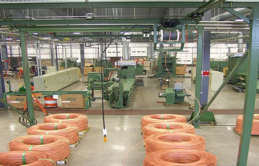
OWL WIRE AND CABLE LLC

                     Catalog Index
                           About Us
Our History and Capabilities               Pages 3,4
                       Our Products
Single End ASTM B-1,B-3,B-33,B-246         Page 5
Concentric Strand ASTM B-8                 Page 6
Bunch Rope Lay Stranded ASTM B-172         Page 7
Concentric Rope Lay Stranded ASTM B-173    Page 7
Bunched Strand ASTM B-174                  Page 8
Combination Unilay ASTM B-787              Page 9
Compact Concentric Strand ASTM B-496       Page 10
ASTM B-296 Type II Stranded                Page 10
Contact our Sales Team                     Page 11
Quality Policy
                        Resources
Glossary of Wire Terms                     Pages 12,13
Wire and Cable Facts                       Pages 14-18
American Wire Gauge (AWG) Chart            Page 19
                                                         Page 2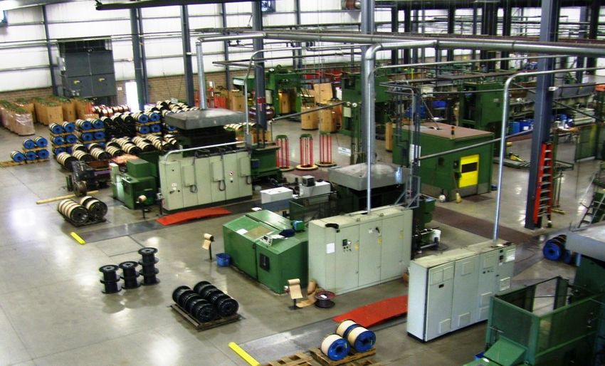
PROJECT
STATUS REPORT
JUNE 8, 2022
OWL WIRE AND CABLE LLC
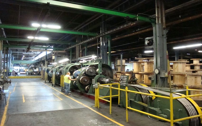
Markets Owl Wire and Cable LLC was founded in 1954 and has
We grown to be a world-class manufacturer of uninsulated
Support wire and cable for multiple markets, with three
manufacturing facilities totaling over 350,000 square feet
of manufacturing space.
Industrial OWL Wire and Cable LLC is a subsidiary of International
Wire Group, joining in 2019.
Energy
Owl Wire and Cable LLC is
Electronics committed to safely
manufacturing the highest
Data quality wire products that
Communication satisfy the expectations of our
customers. The customers we
Consumer serve, and their success, is the
Appliance most vital objective of our
company. We will accomplish
Automotive this objective by continually
improving our products,
processes, and people. Page 3
PROJECT
STATUS REPORT
JUNE 8, 2022

      OWL WIRE AND CABLE LLC

      We manufacture Bare Copper and Electroplated Tin
      Copper wire and cable products within our three
      manufacturing facilities in New York.

          Our Canastota Plant, also OWL Wire and Cable HQ,
          primarily produces bunched and specialty wire
          Our Rome Plant specializes in producing copper
          cables
          Our Boonville Plant specializes in producing single
          end bare and tinned wire

      We guarantee high quality and short lead times.
      Product Lines include circuit sizes through MCM sizes in
      bunched, concentric, unilay, compressed, cables with
      bunched or concentrically stranded members constructed
      as unidirectional, reverse lay, and unilay constructions up
      to 2,000 MCM.
             We also offer a wide range of Class B and Class I
             lightweight conductors meeting the requirements
             of both ASTM and UL for copper savings.

                                                                Page 4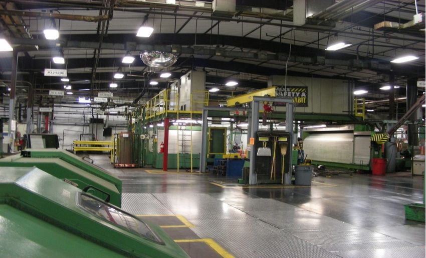
PROJECT
STATUS REPORT
JUNE 8, 2022

            OWL WIRE AND CABLE LLC

                     Our Products
Conductor Classification    Min AWG Size         Max AWG Size

 B-1 This specification covers hard-drawn round copper wire
 for electrical purposes.
   Hard Bare Copper            24 AWG       to      6 AWG

 B-3 This specification covers drawn and annealed or soft
 round bare copper wire for electrical purposes.
   Soft Bare Copper            24 AWG       to      6 AWG

 B-33 This specification covers tin-coated, round, soft, or
 annealed copper wire for electrical purposes.
   Soft Tin Copper             24 AWG       to      8 AWG

 B-246 This specification covers tin-coated, hard-drawn, and
 medium-hard drawn round copper wire for electrical purposes.
   Hard Tin Copper             24 AWG       to      10 AWG

                                                                Page 5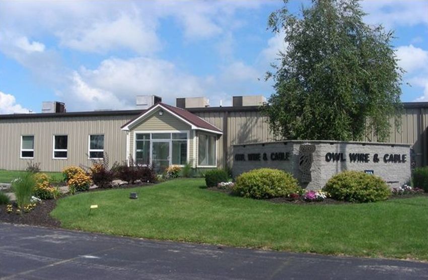
PROJECT
STATUS REPORT
JUNE 8, 2022

            OWL WIRE AND CABLE LLC

                  Our Products
Conductor Classification    Min AWG Size        Max AWG Size

B-8 This specification covers bare concentric-lay stranded
conductors made from round copper wires, either uncoated or
coated with tin, for general use for electrical purposes. These
conductors shall be constructed with a central core
surrounded by one or more layers of helically laid wires.

   Class A Bare Copper        4 AWG        to     2,000 MCM

   Class A Tin Copper         4 AWG        to     1,000 MCM

   Class B Bare Copper        18 AWG       to     2,000 MCM

   Class B Tin Copper         18 AWG       to     1,500 MCM

   Class C Bare Copper        18 AWG       to     1,500 MCM

   Class C Tin Copper         18 AWG       to     1,500 MCM

   Class D Bare Copper        14 AWG       to     1,000 MCM

   Class D Tin Copper         14 AWG       to     1,000 MCM

                                                                  Page 6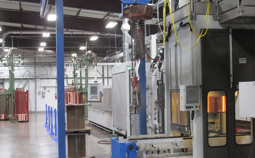
PROJECT
STATUS REPORT
JUNE 8, 2022

            OWL WIRE AND CABLE LLC

                   Our Products
Conductor Classification    Min AWG Size         Max AWG Size

B-172 This specification covers bare rope-lay-stranded
conductors having bunch-stranded members made from
round copper wire, either uncoated or coated with tin, for use
as electrical purposes.
   Class I Bare Copper         6 AWG        to     2,000 MCM
   Class I Tin Copper          6 AWG        to     2,000 MCM
   Class K Bare Copper         9 AWG        to     1,000 MCM

   Class K Tin Copper          9 AWG        to     1,000 MCM

B-173 This specification covers bare rope-lay-stranded
conductors having concentric-stranded members made from
round copper wires, either uncoated or coated with tin, for use
as electrical conductors.
   Class G Bare Copper        10 AWG        to     1,500 MCM
   Class G Tin Copper         10 AWG        to     1,500 MCM
   Class H Bare Copper         6 AWG        to     1,000 MCM

   Class H Tin Copper          6 AWG        to     1,000 MCM

                                                                  Page 7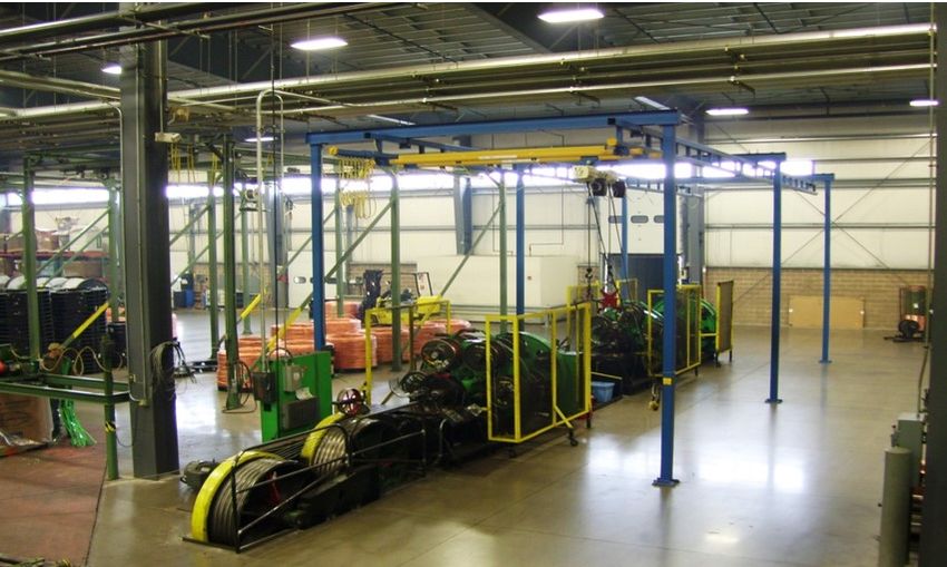
PROJECT
STATUS REPORT
JUNE 8, 2022

            OWL WIRE AND CABLE LLC

                   Our Products
Conductor Classification   Min AWG Size        Max AWG Size

B-174 This specification covers bare bunch-stranded
conductors made from round copper wire, either uncoated or
coated with tin, for use as electrical purposes.

   Class I Bare Copper      10 AWG        to      7 AWG

   Class I Tin Copper       10 AWG        to       7 AWG

   Class J Bare Copper      20 AWG        to      10 AWG

   Class J Tin Copper       20 AWG        to      10 AWG

   Class K Bare Copper      20 AWG        to      10 AWG

   Class K Tin Copper       20 AWG        to      10 AWG

                                                              Page 8
PROJECT
STATUS REPORT
JUNE 8, 2022

             OWL WIRE AND CABLE LLC

                   Our Products
 Conductor Classification    Min AWG Size         Max AWG Size

B-787 This specification covers bare combination unilay
stranded conductors made from round copper wires, either
uncoated or coated with tin for electrical purposes. These
conductors shall be constructed with a central core wire
surrounded by two layers of helically laid wires, resulting in an
outer diameter equal to the compressed-stranded equivalent
conductor.
    Bare Copper                 8 AWG        to      4/0 AWG
    Tin Copper                  8 AWG        to      4/0 AWG

B-496 This specification covers bare compact round
concentric-lay-stranded conductors made from uncoated
round copper wires for general use for electrical purposes.
These conductors shall be constructed with a central core
surrounded by one or more layers of helically laid compacted
wires.

    Bare Copper                 6 AWG        to     1,000 MCM

                                                                    Page 9
PROJECT
STATUS REPORT
JUNE 8, 2022

             OWL WIRE AND CABLE LLC

                    Our Products
Conductor Classification        Min AWG Size          Max AWG Size

B-286 This specification covers uninsulated metallic-coated
copper conductors for use in hookup wire for electronic
equipment. We are capable of providing a number of Type II
stranded tin-plated conductors.

Customization of constructions is available upon request.
Please contact one of our knowledgeable sales representatives
to assist you:

Mark Riesterer           Teresa Araki             MacKenzie Fox
Sales                    Customer Service         Customer Service
Manager                  Representative           Representative
OWL Wire and Cable LLC   OWL Wire and Cable LLC   OWL Wire and Cable LLC
3127 Seneca Turnpike     3127 Seneca Turnpike     3127 Seneca Turnpike
Canastota, NY 13032      Canastota, NY 13032      Canastota, NY 13032
315-697-2011             315-697-2011             315-697-2011
mriesterer@iwgowl.com    taraki@iwgowl.com        mfox@iwgowl.com

                         Visit Our Website:
                  www.internationalwiregroup.com

                                                                           Page 10
PROJECT
STATUS REPORT
JUNE 8, 2022
OWL WIRE AND CABLE LLC
Quality Policy
Owl Wire and Cable LLC is committed to safely manufacturing the
highest quality wire products that satisfy the expectations of our
customers. The customers we serve, and their success, is the most
vital objective of our company. We will accomplish this objective by
continually improving our products, processes, and people.
Page 11Glossary of Terms & Conductor Information
for Wire & Cable
Alloy: A combination of a metal with one or more elements to form a new material with different properties.
Attenuation: Weakening or reduction of the strength of a transmitted signal through a cable or circuit. It is also a measure of
a cable’s efficiency to transmit a signal at a given frequency.
Anneal: To subject a material to a heat treatment to remove the effects of cold work, lowering its tensile strength, rendering it
softer with greater elongation.
AWG (American Wire Gauge): A standard used to specify the physical size of a solid or stranded conductor primarily used
in the United States. Originally called the Brown and Sharpe Gage.
Bird-caging: A phenomenon that occurs during stranding or insulating where the conductor enters a restriction such as a die
or extrusion tip. The outer layers of strands back-up, spread out, or otherwise separate away from the core strands. The
problem has been attributed to poor stranding techniques and improper tensions during processing.
Break Strength: The maximum load that a specimen attains when tested in tension to fracture.
Bunch Construction: A stranded construction in which the individual strands are randomly laid and twisted in the same lay
direction and same length of lay. The strands do not follow a geometric arrangement or pattern.
Capacitance: A measure of a component’s opposition to a change of voltage in a circuit, specified in farads.
Cast: The natural curvature of a wire when in an unrestrained state.
CMA (Circular Mil Area): A measure of a round wire’s cross-sectional area, calculated by squaring the diameter (in mils) of a
strand and multiplying the result by the number of strands. One circular mil (cmil) is equivalent to the area of a circle 0.001
inch in diameter, equal to 7.854 X 10⁻⁷ in2.
Concentric Construction: A central wire surrounded by one or more layers of helically laid wires in a geometric pattern.
Concentric constructions have 7, 19, 37, 61, etc. strands.
Conductivity: The inverse of resistivity and a measure of a material’s ability to conduct electric current. It is usually compared
to that of annealed copper, and is generally stated in terms of %IACS.
Elongation: A measure of a material’s ability to stretch or elongate prior to fracture. It is expressed as a percentage (increase
in length) over a specified gauge length (typically 10 inches for wire).
Equilay Concentric: A central wire surrounded by one or more layers of helically laid wires in a geometric pattern, with
alternately reversed lay direction and the same lay length.
Flex Life (or Flex Fatigue Life): The number of cycles a sample can withstand when subjected to a repetitive stress or strain
mode before failure.
Flexibility: The capability of being bent when an external force is applied, its pliability or limberness. Low flexibility translates
to being more rigid or stiff.
Gauge (or Gage): A term used to designate the physical size of a wire or strand. Some definitions specify “Gage” as a size
designation and “Gauge” as a measuring device (such as pressure gauge). These terms are often used interchangeably.
Hard Drawn: A term referring to the temper of conductors that are drawn without annealing to the finish temper.
IACS: International Annealed Copper Standard
Impedance: The analog of resistance in an AC (alternating current) circuit. Impedance depends upon the resistance,
inductance, capacitance and frequency of the circuit. The unit of impedance is the ohm.
Inductance: A measure of a component’s opposition to a change in the current of a circuit, specified in henries.
Inter-metallic Compound: Two or more metals with a chemical composition based on a definite atomic formula. Inter-
metallics may have a fixed stoichiometric or a very narrow range of chemical composition.
Custom constructions are available, please contact our Sales Department
The information provided on this page is for reference purposes only.
Owl Wire and Cable LLC • 3127 Seneca Turnpike • Canastota, N.Y. U.S.A.
Phone: 315-697-2011 • Web: www.internationalwiregroup.com
Page 12Glossary of Terms & Conductor Information
for Wire & Cable
Lay Direction: The helical direction of the strands or members in any layer of a stranded construction. The two lay
directions are usually denoted as “S” (left hand lay) or “Z” (right hand lay).
Lay Factor: The ratio of the lay length to the external diameter of the corresponding layer of wires or members in the
stranded conductor.
Lay Length (length of lay): The axial length for one revolution of a strand or member in any layer of a stranded or rope
stranded construction.
MCM: An area unit equivalent to 1,000 circular mils. MCM may also be referred to as kcmil.
Ohm: A unit of electrical resistance defined as the resistance necessary to produce 1 ampere of current to flow in a circuit
with an applied potential of 1 volt.
Plating Percentage: See Volume Percentage of Plating and Weight Percentage of Plating.
Plating Thickness: The measured thickness of the plated coating on a wire strand. Measurements are usually in micro-inches
(millionths of an inch) or microns (millionths of a meter).
Polysulfide Testing: A test method that exposes a sample to a sodium polysulfide solution to qualitatively determine the
continuity of the plating on a wire strand. The test method is specified in ASTM B 298 and B 355.
Resistance: A measure of a component’s opposition to the flow of electric current, specified in ohms.
Resistivity: The characteristic of a material to impede the flow of electrons (electrical current). It is the material’s electrical
resistance for a unit volume. This value is specific to a material and not its geometry.
Rope Construction: A conductor composed of separate stranded constructions that are then twisted into the final
construction.
Rope Member: A bunched or concentric stranded construction subsequently stranded again to form a rope construction.
Stranding Factor: The increase in weight and electrical resistance of a conductor due to the lay length of the strands or
members.
Temperature Coefficient of Resistance: The change in a material’s electrical resistance (resistivity) due to a change of one
degree in temperature. It is expressed in units per ºC (or units per ºF).
Tensile Strength: The maximum longitudinal tensile stress that may be applied to a material without fracturing or
rupturing, calculated to a reference unit (lbs/in2, kg/mm2, etc.) by dividing the breaking load by the cross-sectional area.
Tensile Stress: Force per unit cross-sectional area applied to a material.
True Concentric: A central wire surrounded by one or more layers of helically laid wires in a geometric pattern, with
alternately reversed lay direction and increasing lay length.
Tubular Strander: A type of twisting machine where the payoffs are located inside the tube and the take-up is external.
Unidirectional Concentric: A central wire surrounded by one or more layers of helically laid wires in a geometric pattern,
with the same lay direction and an increasing lay length.
Unilay (Unidirectional Equilay Concentric): A central wire surrounded by one or more layers of helically laid wires in a
geometric pattern, with the same lay direction and the same lay length.
Volume Percentage of Plating: The ratio of the volume of the plated material to the total volume of the conductor.
Weight Percentage of Plating: The ratio of the weight of the plated material to the total weight of the conductor. Conductor
plating percentages usually refer to weight percentage when a distinction is not made.
Weight per Unit Length: A method of specifying the weight of conductor or wire using a standard length. Common lengths
of 1,000 feet or 1,000 meters are used, however other lengths may also be specified.
Custom constructions are available, please contact our Sales Department
The information provided on this page is for reference purposes only.
Owl Wire and Cable LLC • 3127 Seneca Turnpike • Canastota, N.Y. U.S.A.
Phone: 315-697-2011 • Web: www.internationalwiregroup.com
Page 13Wire and Cable Facts - Lay Direction and Length
Lay Direction
Stranded conductors are manufactured by twisting strands of non-insulated wire. The direction of twisting is
designated as the “lay direction”. The degree of twist per unit length defines the “lay length”.
The lay direction is determined by the direction the
machine is turning during the stranding operation. The
conventional method to determine the lay direction is
to observe the upper surface of the stranded conductor
with one end pointing toward you and the wire leading
away from you:
If the strands turn left leading away from the observer and
have the same slant as the middle of the letter “S”, the
convention denotes an “S” lay direction.
If the strands turn right leading away from the observer
and have the same slant as the middle of the letter “Z”, the
convention denotes a “Z” lay direction.
Lay Length
Lay length is defined as the distance required to complete one revolution of the strand around the diameter of the
conductor.
When a conductor has more than one layer, it usually refers to the lay length of the outer layer. In the case of
Unilay, Equilay and bunch, the lay length of all layers is equal. In True Concentric and Unidirectional, the lay
lengths of the inner layers are less, this also holds true for rope constructions.
General Practices
There are some general practices that pertain to the lay direction and lengths of conductor as specified by industry
standards such as ASTM, NEMA and military, however, requirements for specific applications vary.
Custom constructions are available, please contact our Sales Department
The information provided on this page is for reference purposes only.
Owl Wire and Cable LLC • 3127 Seneca Turnpike • Canastota, N.Y. U.S.A.
Phone: 315-697-2011 • Web: www.internationalwiregroup.com
Page 14Wire and Cable Facts - Lay Direction and Length
Direction of the outer layer
The direction away from the outer layer of strands or members is usually S. Inner layer directions depend upon the
construction (True concentric, Unilay, etc).The lay length of the outer layer of strands or members varies with different
applications.
Length of the outer layer
For most conductor applications, lay lengths of between 8 – 16 times the outer diameter of a given layer are specified in
ASTM B 286. In general, lay lengths in the range of 12 – 15 times the outer diameter are used for tighter tolerance and
geometric pattern control. Shorter lay lengths of 12 times or less have the disadvantage of slightly higher weight per unit
length.
For 7 strand and bunch applications, where tight diameter tolerance is less of a concern, lay lengths in excess of 30 times
the outer diameter are common. Longer lay lengths are sometimes preferred by customers for cost, yield and weight
considerations.
Stranding Factors
The increase in weight and resistance due to stranding can be calculated mathematically. ASTM refers to this increase as
the stranding or “k-factor”, defined as “incremental percentage (increase) of weight and electrical resistance.” ASTM B 8,
B 229, B 231, and others give a method of calculating the “k“:
k = 100 (m – 1)
Where k is the incremental (increase) in mass and electrical resistance, the factor m is the ratio of the mass or electrical
resistance of a unit length of the stranded conductor to that of a conductor monofilament of the same section or that of
the stranded conductor with an infinite length of lay (all the strands run parallel to the axis). The factor m of the strand
is the average of the factors for each of the individual wires in the conductor including the straight wire core, if any (for
which the lay factor is unity).
The lay factor mind for any given wire in a concentric stranded conductor is calculated as follows:
Where n = (length of lay) + (diameter of helical path of wire)
Example: the lay factor for a 19 strand conductor is the numerical average of the 19 individual strands:
m = (1 + 6m6 = 12m12) ÷ 19
Where m6 = m ind calculated for each of the 6 strands of the inner layer
and m12 = m ind calculated for each of the 12 strands of the outer layer
Custom constructions are available, please contact our Sales Department
The information provided on this page is for reference purposes only.
Owl Wire and Cable LLC • 3127 Seneca Turnpike • Canastota, N.Y. U.S.A.
Phone: 315-697-2011 • Web: www.internationalwiregroup.com
Page 15Wire and Cable Facts - Strand Configurations
Stranded conductors are composed of un-insulated strands of wire twisted together. The advantages of stranded
conductor over a single strand of equal cross-section are increased flexibility and flex-fatigue life. Stranded conductor can
be manufactured in a variety of configurations, the most common being concentric, bunched and ropes.
Concentric
When the term “concentric stranding” is used, it refers to the definition of the word “concentric”, which is having a
“common center”.
Concentric conductor may be defined as:“A central wire (strand) surrounded by one or more layers of helically laid wires
in a geometric pattern.”
The geometric pattern requires that concentric constructions can only be produced with 7, 19, 37, 61, (etc.) strands or
members, following the pattern that each successive layer has 6 more strands than the layer below it. In all types of
concentric constructions, the geometric pattern of the strands is consistent for the entire length of the conductor. That is,
the central strand, and the strands in each layer remain in their respective positions from the beginning to the end of its
length.
The main advantage of concentric constructions is the close/tight diameter tolerances that can be maintained on the
conductor. Concentric constructions have very smooth uniform surfaces that are suited for thin wall insulation in high
performance applications.
Concentric Stranding
There are four common types of concentric constructions manufactured for the high performance wire and cable
industry. Although there are 4 distinct types, the industry normally refers to “Concentric” as “True Concentric” and will
use the terms interchangeably. The other types are referenced as noted.
Concentric or True Concentric characterized by a central wire surrounded by one or more layers of
helically laid wires in a geometric pattern, with alternately reversed lay direction and increasing lay
length.
Equilay or Equilay Concentric characterized by a central wire surrounded by one or more layers of
helically laid wires in a geometric pattern, with alternately reversed lay direction and the same lay length.
Custom constructions are available, please contact our Sales Department
The information provided on this page is for reference purposes only.
Owl Wire and Cable LLC • 3127 Seneca Turnpike • Canastota, N.Y. U.S.A.
Phone: 315-697-2011 • Web: www.internationalwiregroup.com
Page 16Wire and Cable Facts - Strand Configurations
Unidirectional or Unidirectional Concentric
Wire is characterized by a central wire surrounded by one or more layers of helically laid wires in a geometric
pattern, with the same lay direction and an increasing lay length.
Unilay or Unidirectional Equilay Concentric
Wire is characterized by a central wire surrounded by one or more layers of helically laid wires in a geometric
pattern, with the same lay direction and the same lay length.
Bunched Stranding
Bunch strand wire contains any number of strands in random pattern. Twisted in one operation, all strands
have the same lay direction and same lay length, however, the result is a rougher surface and lower dimensional
tolerance than the concentric constructions. The number of strands is determined by the size of the individual
strands and the total cross-sectional area required.
Custom constructions are available, please contact our Sales Department
The information provided on this page is for reference purposes only.
Owl Wire and Cable LLC • 3127 Seneca Turnpike • Canastota, N.Y. U.S.A.
Phone: 315-697-2011 • Web: www.internationalwiregroup.com
Page 17Wire and Cable Facts - Strand Configurations
Rope Stranding
Wire constructions consist of single strands assembled together into concentric or bunched
configurations. Rope constructions consist of concentric or bunched members stranded together into the
final concentric or bunched configuration.
Rope stranding has the advantage of increasing flexibility by using a larger number of finer strands while
maintaining a tighter diameter tolerance than a simple bunched construction. Ropes are more evident in
the larger AWG sizes, such as 8 AWG and larger, but there also many applications that require the
flexibility of rope constructions in the smaller gauges. Constructions vary and can contain hundreds or
thousands of strands.
Custom constructions are available, please contact our Sales Department
The information provided on this page is for reference purposes only.
Owl Wire and Cable LLC • 3127 Seneca Turnpike • Canastota, N.Y. U.S.A.
Phone: 315-697-2011 • Web: www.internationalwiregroup.com
Page 18American Wire Gauge Chart
Diameter Area Resistance Pounds per
AWG (in) (mm) (kcmil) (mΩ/m) (mΩ/ft) 1,000 ft Feet Per Pound
0000 (4/0) 0.4600 11.684 212.000 0.1608 0.04901 640.0000 1.56
000 (3/0) 0.4096 10.405 168.000 0.2028 0.0618 509.0000 1.96
00 (2/0) 0.3648 9.266 133.000 0.2557 0.07793 403.0000 2.48
0 (1/0) 0.3249 8.251 106.000 0.3224 0.09827 318.0000 3.14
1 0.2893 7.348 83.700 0.4066 0.1239 256.0000 3.91
2 0.2576 6.544 66.400 0.5127 0.1563 200.0000 5.00
3 0.2294 5.827 52.600 0.6465 0.197 159.0000 6.29
4 0.2043 5.189 41.700 0.8152 0.2485 126.0000 7.94
5 0.1819 4.621 33.100 1.028 0.3133 100.0000 10.00
6 0.1620 4.115 26.300 1.296 0.3951 79.4000 12.59
7 0.1443 3.665 20.800 1.634 0.4982 62.8000 15.92
8 0.1285 3.264 16.500 2.061 0.6282 49.6000 20.16
9 0.1144 2.906 13.100 2.599 0.7921 39.3000 25.45
10 0.1019 2.588 10.400 3.277 0.9989 31.5000 31.75
11 0.0907 2.305 8.230 4.132 1.26 24.9000 40.16
12 0.0808 2.053 6.530 5.211 1.588 19.8000 50.51
13 0.0720 1.828 5.180 6.571 2.003 15.7000 63.69
14 0.0641 1.628 4.110 8.286 2.525 12.4000 80.65
15 0.0571 1.45 3.260 10.45 3.184 9.8700 101.32
16 0.0508 1.291 2.580 13.17 4.016 7.8100 128.04
17 0.0453 1.15 2.050 16.61 5.064 6.2100 161.03
18 0.0403 1.024 1.620 20.95 6.385 4.9200 203.25
19 0.0359 0.912 1.290 26.42 8.051 3.9000 256.41
20 0.0320 0.812 1.020 33.31 10.15 2.9500 338.98
21 0.0285 0.723 0.810 42 12.8 2.4600 406.50
22 0.0253 0.644 0.642 52.96 16.14 1.9500 512.82
23 0.0226 0.573 0.509 66.79 20.36 1.5500 645.16
24 0.0201 0.511 0.404 84.22 25.67 1.2200 819.67
25 0.0179 0.455 0.320 106.2 32.37 0.9700 1,030.93
26 0.0159 0.405 0.254 133.9 40.81 0.7650 1,307.19
27 0.0142 0.361 0.202 168.9 51.47 0.6100 1,639.34
28 0.0126 0.321 0.160 212.9 64.9 0.4800 2,083.33
29 0.0113 0.286 0.127 268.5 81.84 0.3860 2,590.67
30 0.0100 0.255 0.101 338.6 103.2 0.3030 3,300.33
31 0.0089 0.227 0.080 426.9 130.1 0.2410 4,149.38
32 0.0080 0.202 0.063 538.3 164.1 0.1910 5,235.60
33 0.0071 0.18 0.050 678.8 206.9 0.1520 6,578.95
34 0.0063 0.16 0.040 856 260.9 0.1200 8,333.33
35 0.0056 0.143 0.032 1079 329 0.0950 10,526.32
36 0.0050 0.127 0.025 1361 414.8 0.0760 13,157.89
37 0.0045 0.113 0.020 1716 523.1 0.0600 16,666.67
38 0.0040 0.101 0.016 2164 659.6 0.0476 21,008.40
39 0.0035 0.0897 0.013 2729 831.8 0.0377 26,525.20
40 0.0031 0.0799 0.010 3441 1049 0.0299 33,444.82
Page 19You can also read


