POLAR TEMP ICE MERCHANDISER INSTALLATION, OPERATION, & MAINTENANCE MANUAL
←
→
Page content transcription
If your browser does not render page correctly, please read the page content below
POLAR TEMP ICE MERCHANDISER
 INSTALLATION, OPERATION, &
    MAINTENANCE MANUAL

         www.polartemp.com

          C         US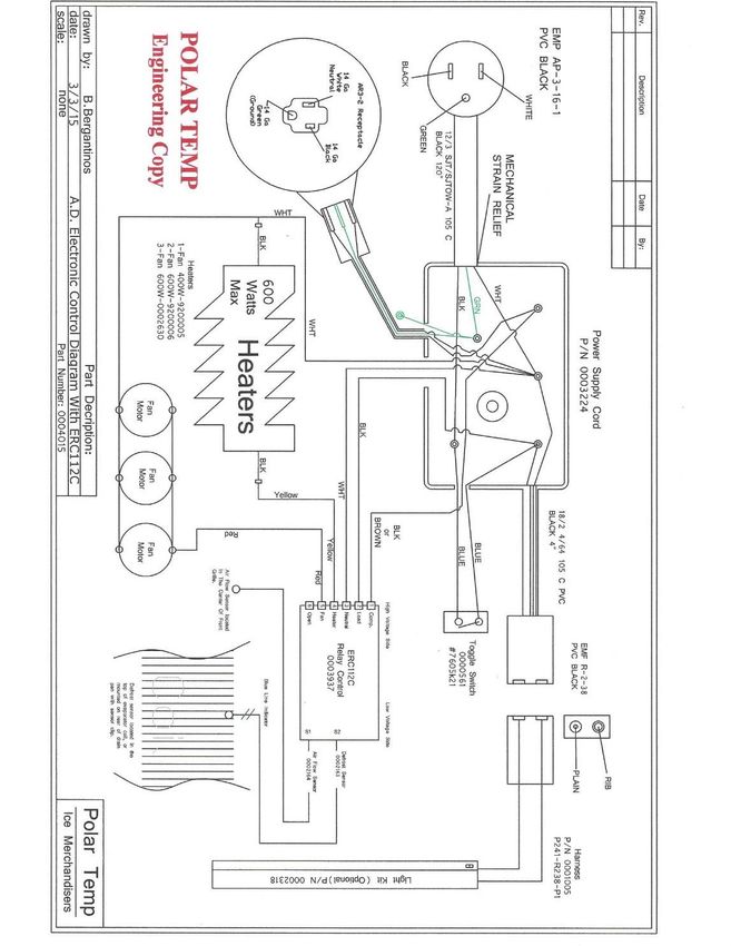
TABLE OF CONTENTS
Disclaimer . . . . . . . . . . . . . . . . . . . . . . . . . . . . . . . . . . . . . . . . . . Page 3
Inspection and unpacking . . . . . . . . . . . . . . . . . . . . . . . . . . . . . . Page 4
Installation . . . . . . . . . . . . . . . . . . . . . . . . . . . . . . . . . . . . . . . . . . Page 4
Before Operation . . . . . . . . . . . . . . . . . . . . . . . . . . . . . . . . . . . Page 5
Operation . . . . . . . . . . . . . . . . . . . . . . . . . . . . . . . . . . . . . . . . . . . Page 5 - 9
Electrical
Temperature Control – Cold Wall, Automatic Defrost, Electronic Automatic Defrost
Load with Bagged Ice
Maintenance . . . . . . . . . . . . . . . . . . . . . . . . . . . . . . . . . . . . . . . . Page 9 - 11
Refrigeration
Defrosting
Cold Wall (CW)
Auto Defrost (AD)
Doors
Gaskets
Hinges
Finish
Cold Wall Wiring Diagram – Mechanical Controls . . . . . . . . . . . . . . Page 12
Automatic Defrost Wiring Diagram – Mechanical Controls . . . . . . . . Page 13
Automatic Defrost Wiring Diagram w/ ETC-1H Electronic Control . . . Page 14
Automatic Defrost Wiring Diagram w/ERC112C Electronic Control . . Page 15
Automatic Defrost Wiring Diagram w/ERC102C Electronic Control . . Page 16
Cold Wall Wiring Diagram w/ERC101A Electronic Control . . . . . . . Page 17
Automatic Defrost Trouble Shooting Guide . . . . . . . . . . . . . . . . . . . Page 18 - 19
Cold Wall Troubleshooting Guide . . . . . . . . . . . . . . . . . . . . . . . . . . . . Page 20
Refrigeration and Electrical Diagnostic Guide . . . . . . . . . . . . . . . . . . Page 21 - 25
Refrigeration Data and Specifications . . . . . . . . . . . . . . . . . . . . . . . . . Page 26 - 28
Policy Statement . . . . . . . . . . . . . . . . . . . . . . . . . . . . . . . . . . . . . . . . . Page 29 - 30
Warranty
Parts Orders
Method of Shipment
Ship Dates
Return of Merchandise
Pricing
Ordering addresses, telephone numbers and websites
Factory Sales Locations . . . . . . . . . . . . . . . . . . . . . . . . . . . . . Page 31
Polar Temp
A Division of Southeast Cooler Corporation
Installation, Operation & Maintenance Manual Part Number 0000545
Revisions 2/2/05, 01/06/11, 06/08/11, 05/18/12, 06/15/15
2 of 31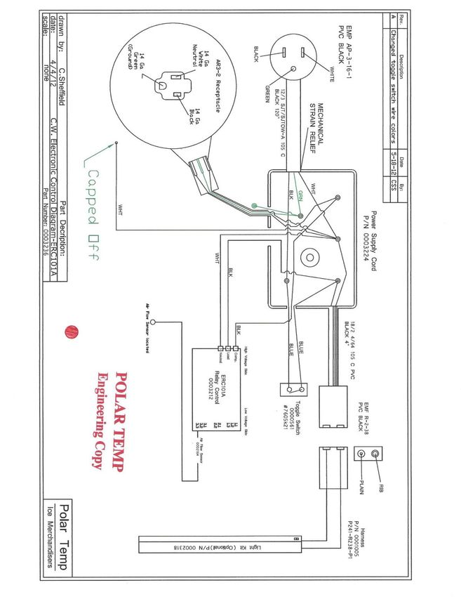
DISCLAIMER

 Polar Temp is committed to continuous material and product improvements. This
manual is subject to modification without notice without incurring responsibility for
                  previously sold merchandisers and components.

                     Thank you for purchasing from Polar Temp.

              State of California Proposition 65 Warnings

WARNING: This product contains one or more chemicals known to the State of
California to cause cancer.

WARNING: This product contains one or more chemicals known to the State of
California to cause birth defects or other reproductive harm.

                                              Polar Temp
                               A Division of Southeast Cooler Corporation
                 Installation, Operation & Maintenance Manual Part Number 0000545
                        Revisions 2/2/05, 01/06/11, 06/08/11, 05/18/12, 06/15/15
                                                 3 of 31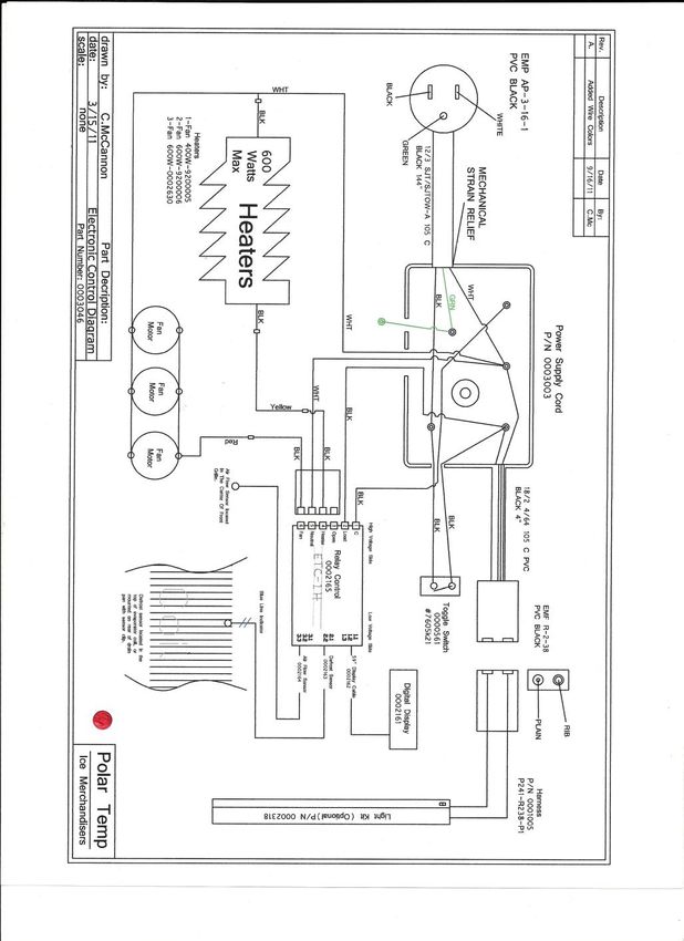
INSPECTION AND UNPACKING:
Polar Temp merchandisers are individually inspected and carefully packaged to ensure
each unit arrives without damage.
Upon receipt, immediately inspect the merchandiser for any evidence of
shipping damage while the delivery truck driver is there. If the
merchandiser is damaged, document damage on the bill of lading and give
the driver a copy. Notify the delivering carrier immediately and request a
damage inspection and claim. Polar Temp is not responsible for damage to
merchandisers during transit. A merchandiser damaged in transit is the
delivering carrier’s responsibility.
Remove plastic stretch wrap and merchandiser corner protectors. The wooden
skid is removed by extracting the hex head screws holding it to the
merchandiser bottom
The merchandiser should be moved in an upright position. If the
merchandiser is tilted past 45 degrees, it is recommended that it not be used
for a time equal to the time it was tilted. This will allow the compressor
lubricant to drain back to normal position.
INSTALLATION:
Install the merchandiser for customer convenience, easy access and maximum exposure.
The location must provide good ventilation for the refrigeration system. DO NOT
BLOCK AIRFLOW TO THE CONDENSING UNIT.
Outdoor merchandisers should be placed on a flat, level surface allowing
water drainage away from merchandiser. The surface should also be strong
enough to support the merchandiser with a load of ice. Be sure to check the
load capacity of the merchandiser prior to installation. If the merchandiser is
not level, the self-closing doors on upright models may not close or seal
properly.
Polar Temp
A Division of Southeast Cooler Corporation
Installation, Operation & Maintenance Manual Part Number 0000545
Revisions 2/2/05, 01/06/11, 06/08/11, 05/18/12, 06/15/15
4 of 31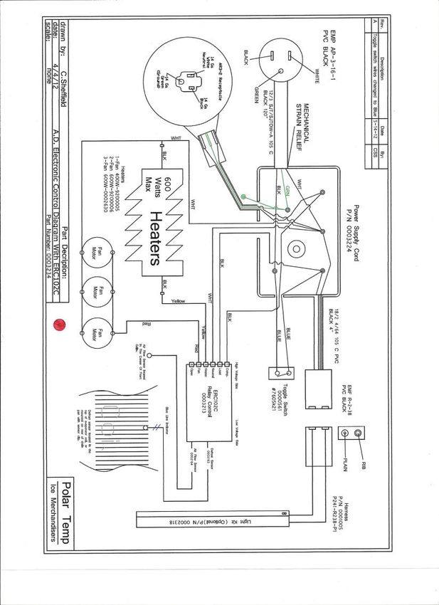
It is essential that auto-defrost models be placed on a level surface or tipped to
the rear slightly to allow defrost drain pan water to drain properly. If defrost
water does not drain, it will freeze in the drain pan which can eventually cause
the fans to seize.
Auto-defrost models should be installed leaving sufficient distance behind the
merchandiser to prevent the evaporator drain hose from being kinked or hose
opening from being obstructed.
Auto-defrost models with a condensate evaporator on the back should not be
placed directly against or touching a wall.
Adequate space should be allowed around the exterior walls of the
merchandisers to allow for evaporation of any condensation that may occur on
cabinet exterior.
Outdoor merchandisers should be located in a shaded area away from direct
sunlight for the most economical operation.
A minimum 115 Volt, 15 Amp grounded power source should be provided
within a range of the power cord. DO NOT USE EXTENSION CORDS.
BEFORE OPERATION:
Glass Door Models:
Some glass door models have support brackets that need to be
removed.
Auto-defrost Glass (ADG) Door Models:
Install condensate evaporator unit on rear of cabinet. Screwdriver is
required.
OPERATION:
Electrical:
The electrical power supplied to the merchandiser must be as identified on the
serial number data plate located on the inside of the merchandiser. Electrical
service connections must be in accordance with the National Electrical Code, state
code and any local codes that may apply. All merchandisers are equipped with a
power cord and a 3-prong plug. WARNING: Improper use or removal of the
grounding plug can result in a risk of electric shock!
Be sure to use a grounded electrical receptacle with a fused circuit sized correctly
for the electrical load. Do not use extension cords. Extension cords may
decrease the voltage to the unit and ultimately cause the compressor or other
component failure. The merchandiser data plate indicates the recommended
maximum over current protective device size.
Polar Temp
A Division of Southeast Cooler Corporation
Installation, Operation & Maintenance Manual Part Number 0000545
Revisions 2/2/05, 01/06/11, 06/08/11, 05/18/12, 06/15/15
5 of 31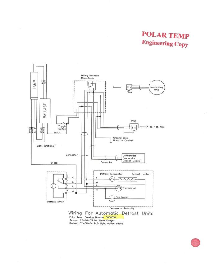
Note: Some outdoor locations require ground fault interrupt (GFI) outlets. These
outlets may trip upon condensing unit start. Refrigeration equipment is exempt in
some areas from GFI requirements. Local electric codes should be checked.

Start Up:
Plug merchandiser power cord into lower receptacle of electrical outlet. The
condensing unit will start immediately (electronically controlled models have a
delay on startup) and the unit cooler evaporator fans will start on the auto-defrost
models. The condensing unit will continue to run until air temperature inside the
merchandiser reaches 10º F and then cycle on and off between 10º F and 20º F.
If the merchandiser has a condensate evaporator, plug the power cord from it into
the upper receptacle of electrical outlet.

Mechanical Temperature Control:
                              Automatic Defrost Models
                              Previous to November 2010
Merchandiser temperature is maintained by a mechanical thermostat that cycles
the condensing unit on and off automatically. On auto-defrost (AD) models, the
temperature control is located on the left end of the evaporator blower coil
assembly. On cold wall models, the control is located on a bracket under the
condensing unit cover. Most mechanical control models will have the standard
mechanical defrost timer. An electronic defrost timer (AT1032-1 is/was an
option) If AT1032-1 is used, the compressor will start momentarily, turn off and
then go into defrost immediately for 15 minutes to be sure the coil is free of frost
and ice. Every time the unit is switched off then will start a new defrost cycle
with the AT1032-1.

The temperature is adjusted by turning the thermostat control knob clock-wise for
colder temperature and counter-clockwise for warmer temperatures. Turning the
control knob fully counter-clockwise will shut power off to the compressor. DO
NOT re-adjust the internal adjustments of the thermostat without consulting Polar
Temp.

Electronic Temperature Control:
                               Automatic Defrost Models – ETC-1H
                               November 2010 to March 2012
Merchandiser temperature is maintained by an electronic thermostat that cycles
the condensing unit on and off automatically. On auto-defrost (AD) models, the
temperature control is located on the left end under the hood on outdoor units and
to the left of the condensing unit on indoor skirt hood models.

Minimal temperature adjustment (2 degrees F min/max adjustment) is possible by
turning the thermostat control knob clock-wise for colder temperature and

                                           Polar Temp
                            A Division of Southeast Cooler Corporation
              Installation, Operation & Maintenance Manual Part Number 0000545
                     Revisions 2/2/05, 01/06/11, 06/08/11, 05/18/12, 06/15/15
                                              6 of 31
counter-clockwise for warmer temperatures since the electronic control is pre-set
at the factory. DO NOT adjust the thermostat without consulting Polar Temp.

The electronic control is factory set with a computer therefore there is no need to
make field adjustments. The digital display on your new Polar Temp Ice
Merchandiser will show fault codes and other information as described below:

“E1” on the digital display means “faulty air sensor”
“E2” on the digital display means “faulty defrost sensor”
“---“on the digital display means the refrigeration system has been “turned off”
“def” on the digital display means the refrigeration system is in “defrost cycle”
“E13” on the digital display means “communication error” (cable between the
digital readout and the control relay is faulty)

“VH” indicates “voltage high”
“VL” indicates “voltage low”

Two buttons on the digital display will do the following:

Pressing both buttons at the same time for 10 seconds will shut the refrigeration
system “OFF” (“---“ shown on the digital display)

Pressing the top button for 10 seconds will give you the option of temperature
display in centigrade (C°) or Fahrenheit (Fº)

Pressing the bottom button for 10 seconds will put the refrigeration system into a
manual defrost (“def” shown on the digital display) The system will
automatically return to refrigeration cycle after temperature 50º F or 15 to 20
minutes is satisfied, whichever comes first. The system will go into defrost every
60 minutes of “compressor” run time.

If the electrical power supply is interrupted the electronic control will always start
automatically after a short delay in a new refrigeration cycle.

Electronic Temperature Control:

           Automatic Defrost Models – ERC102C Controller
                        Starting March 2012
           Automatic Defrost Models – EC112C Controller
                         Starting May 2015

Merchandiser temperature is maintained by an electronic thermostat that cycles
the condensing unit on and off automatically. On auto-defrost (AD) models, the
                                           Polar Temp
                            A Division of Southeast Cooler Corporation
              Installation, Operation & Maintenance Manual Part Number 0000545
                     Revisions 2/2/05, 01/06/11, 06/08/11, 05/18/12, 06/15/15
                                              7 of 31
electronic temperature control is located on the left end under the hood on outdoor
units and to the left of the condensing unit on indoor skirt hood models.
Minimal temperature adjustment (5 degrees F min/max adjustment) is possible by
pressing the up or down arrow buttons for colder or warmer temperatures since
the electronic control is pre-set at the factory. DO NOT adjust the thermostat
without consulting Polar Temp.
The electronic control is factory set with a computer at the factory therefore there
is no need to make field adjustments. The digital display on your new Polar
Temp Ice Merchandiser will show fault codes and other information as described
below:
“E01” on the digital display means “faulty air sensor”
“E02” on the digital display means “faulty defrost sensor”
“E03” when used is faulty “condenser air sensor”
“OFF“ on the digital display means the refrigeration system has been “turned off”
“ON“ on the digital display means the refrigeration system has been “turned on”
“def” on the digital display means the refrigeration system is in “defrost cycle”
“VH” indicates “voltage high”
“VL” indicates “voltage low”
The four buttons on the digital display will do the following:
Press and release the bottom left hand button (“OFF or ON“will show on the
digital display)
Press and release the top left hand button will put the system into defrost mode
(“def” will show on the digital display) The system will automatically return to
refrigeration cycle after 15 minute defrost period and the coil defrost temperature
reaches 55º F. If the defrost terminate temperature is not 55°F, it will continue to
a maximum of 25 minutes. The system will go into defrost every 120 minutes of
“compressor” run time.
If the electrical power supply is interrupted the electronic control will always start
automatically in the refrigeration cycle after a short delay.
Electronic Temperature Control:
Cold Wall Models – ERC101A
Starting May 2012
Merchandiser temperature is maintained by an electronic thermostat that cycles
the condensing unit on and off automatically. On cold-wall (CW) models, the
Polar Temp
A Division of Southeast Cooler Corporation
Installation, Operation & Maintenance Manual Part Number 0000545
Revisions 2/2/05, 01/06/11, 06/08/11, 05/18/12, 06/15/15
8 of 31electronic temperature control is located on the left end under the hood on outdoor
units and to the left of the condensing unit on indoor skirt hood models.
Minimal temperature adjustment (5 degrees F min/max adjustment) is possible by
pressing the up or down arrow buttons for colder or warmer temperatures since
the electronic control is pre-set at the factory. DO NOT adjust the thermostat
without consulting Polar Temp.
The electronic control is factory set with a computer at the factory therefore there
is no need to make field adjustments. The digital display on your new Polar
Temp Ice Merchandiser will show fault codes and other information as described
below:
“E01” on the digital display means “faulty air sensor”
“E03” when used is faulty “condenser air sensor”
“OFF“ on the digital display means the refrigeration system has been “turned off”
“ON“ on the digital display means the refrigeration system has been “turned on”
“VH” indicates “voltage high”
“VL” indicates “voltage low”
The four buttons on the digital display will do the following:
Press and release the bottom left hand button (“OFF or ON“ will show on the
digital display)
Manual defrost not active on cold wall units.
Arrow buttons change temperature up or down.
If the electrical power supply is interrupted the electronic control will always start
automatically after a short delay in a new refrigeration cycle.
Loading merchandiser with bagged ice:
After the merchandiser is operating at required temperature, load it with bagged
ice. Bagged ice should not be stacked such that it will obstruct air flow in
automatic defrost blower coil merchandisers.
Cold wall glass door units should have ice stacked to allow open-air access to
thermostat sensor at upper rear interior. Approximately 3” needs to be clear from
top of stacked ice to top of inside interior for effective refrigeration and ice
storage.
MAINTENANCE:
Polar Temp
A Division of Southeast Cooler Corporation
Installation, Operation & Maintenance Manual Part Number 0000545
Revisions 2/2/05, 01/06/11, 06/08/11, 05/18/12, 06/15/15
9 of 31Refrigeration: WARNING – disconnect electrical power before cleaning.
Clean refrigeration cover grill openings, condenser fins, and condenser fan blades
at least two (2) times per year, more often if needed. A dirty condenser will cause
the merchandiser to become less efficient, and may lead to compressor failure.
Clean the evaporator coil and fan blades on auto-defrost merchandisers as
required:
Clean condenser coil fins with a fine bristle brush or vacuum
Routinely check wiring harness for loose connections or broken insulation
Defrosting: Frost cannot be avoided. It develops from moist air entering the
merchandiser when the door is opened and forms on the evaporator. When the frost
accumulation on the evaporator becomes too heavy, it acts as an insulator, which hinders
the refrigeration efficiency.
Excess frost or water on the interior of the merchandiser should be
removed or drained. Do not allow water to stand in or around the cabinet.
Cold Wall (CW): Cold Wall type merchandisers utilize the merchandiser’s interior wall
surface as the refrigeration evaporator. Frost accumulation will occur on all wall
surfaces. The merchandiser can be defrosted by conventional methods using a wooden
paddle or plastic scraper. Care must be exercised to prevent damaging piping and control
parts. Do not use a sharp instrument to “chop” the frost from the interior surface as you
may do irreparable damage. Remove the floor drain plug to allow water to drain.
Auto-Defrost (AD): Auto-Defrost (sometimes referred to as “electric defrost”) type
merchandisers utilize a cooler evaporator with an electric defrost heating element to melt
the frost off the evaporator coil. The defrost cycle is controlled by the electronic control
system which energizes the electric defrost heating element. The electronic control is
located in the condensing unit compartment. The control is programmed to periodically
place the system in a defrost cycle automatically every two to four hours, depending on
your control system, of compressor run time. The length of the defrost cycle is
approximately 14 to 16 minutes minimum and then 55°F at the coil. The electronic
control used is non-adjustable, however, defrost button may be pushed to start a manual
defrost cycle. If your merchandiser has the electronic defrost timer, part number
AT1032-1 (not the electronic control system) you may turn the refrigeration system
“OFF” with the toggle switch or unplug the wall plug, then turn it back to the “ON”
position which will automatically start a manually induced defrost cycle.
Doors: Gaskets should be checked for tears or any other problems that would cause loss
of seal. Replace torn/worn gaskets to maintain correct temperature and refrigeration
efficiency.
Polar Temp
A Division of Southeast Cooler Corporation
Installation, Operation & Maintenance Manual Part Number 0000545
Revisions 2/2/05, 01/06/11, 06/08/11, 05/18/12, 06/15/15
10 of 31Hinges exposed to harsh environmental conditions may require a lubricant for ease of
operation. Spray light penetrating oil on the spring loaded hinge cartridge to extend the
hinge life.
Finish: Schedule periodic cleaning of merchandiser interior and exterior. The cabinet
can be cleaned with a mild detergent and water. DO NOT USE strong detergents,
abrasive cleaners, or solvents, likely to leave objectionable odors which may be absorbed
by the ice. Do not use wax or polish on the interior for the same reason. Wash exterior
surfaces with a mild soap and warm water applied with a soft sponge or cloth. Wax
exterior to maintain appearance and to protect the finish.
Polar Temp
A Division of Southeast Cooler Corporation
Installation, Operation & Maintenance Manual Part Number 0000545
Revisions 2/2/05, 01/06/11, 06/08/11, 05/18/12, 06/15/15
11 of 31Mechanical Controls – Cold Wall
Polar Temp
A Division of Southeast Cooler Corporation
Installation, Operation & Maintenance Manual Part Number 0000545
Revisions 2/2/05, 01/06/11, 06/08/11, 05/18/12, 06/15/15
12 of 31Mechanical Controls Auto Defrost
Polar Temp
A Division of Southeast Cooler Corporation
Installation, Operation & Maintenance Manual Part Number 0000545
Revisions 2/2/05, 01/06/11, 06/08/11, 05/18/12, 06/15/15
13 of 31Electronic Control Auto Defrost ETC-1H
Polar Temp
A Division of Southeast Cooler Corporation
Installation, Operation & Maintenance Manual Part Number 0000545
Revisions 2/2/05, 01/06/11, 06/08/11, 05/18/12, 06/15/15
14 of 31Electronic Control Auto Defrost ERC112C
Polar Temp
A Division of Southeast Cooler Corporation
Installation, Operation & Maintenance Manual Part Number 0000545
Revisions 2/2/05, 01/06/11, 06/08/11, 05/18/12, 06/15/15
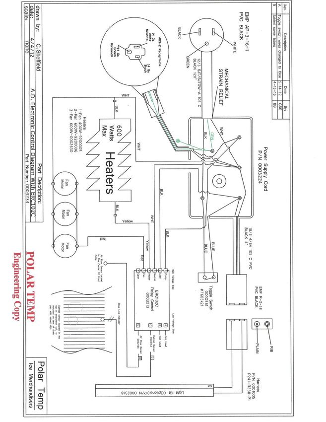
15 of 31Electronic Control Auto Defrost ERC102C
Polar Temp
A Division of Southeast Cooler Corporation
Installation, Operation & Maintenance Manual Part Number 0000545
Revisions 2/2/05, 01/06/11, 06/08/11, 05/18/12, 06/15/15
16 of 31Electronic Control Cold Wall ERC101A
Polar Temp
A Division of Southeast Cooler Corporation
Installation, Operation & Maintenance Manual Part Number 0000545
Revisions 2/2/05, 01/06/11, 06/08/11, 05/18/12, 06/15/15
17 of 31AUTOMATIC DEFROST TROUBLE
SHOOTING GUIDE
If refrigerant valves must be opened, a qualified technician should be notified to perform the work.
Problem Possible Cause Solution
Ice is melting Power switch is in OFF position Turn switch to ON
position.
Ice bags are blocking air flow Move ice bags accordingly.
Thermostat setting Normal setting is between 4 and 6
on the dial. Jump terminals on
thermostat to check, if unit starts,
replace thermostat.
Evaporator fan motors are Check to see if fan blade is
operating but the fan blade slipping on the motor shaft.
not turning
Condenser coil is dirty Clean condenser.
Incorrect refrigerant charge Check sight glass when used for
bubbles indicating wrong charge.
Add refrigerant. Locate refrigerant
leak.
Condenser fan motor and Check power supply.
compressor are not running Check if defrost timer (mechanical
controls) is stuck in defrost mode
Check if compressor is hot, this
may indicate that
condenser fan motor has failed
causing thermal overload on
compressor to trip.
Condenser fan motor is not Check electrical power to
operating motor.
Compressor is not operating Check electrical power, relay,
overload protector, start capacitor
and compressor motor.
Polar Temp
A Division of Southeast Cooler Corporation
Installation, Operation & Maintenance Manual Part Number 0000545
Revisions 2/2/05, 01/06/11, 06/08/11, 05/18/12, 06/15/15
18 of 31AUTOMATIC DEFROST TROUBLESHOOTING GUIDE - continued
Problem Possible Cause Solution
Ice is melting Evaporator fan Check power supply to motor
motor not running Check for faulty fan motor
Check for ice build-up Check power to defrost heater
on the evaporator coil Check defrost heater for heat
Check defrost termination thermostat
Check defrost timer
Polar Temp
A Division of Southeast Cooler Corporation
Installation, Operation & Maintenance Manual Part Number 0000545
Revisions 2/2/05, 01/06/11, 06/08/11, 05/18/12, 06/15/15
19 of 31COLD WALL TROUBLESHOOTING GUIDE
If refrigerant valves must be opened, a qualified technician should be notified to perform the work.
Problem Possible Cause Solution
Ice is melting Power switch is in OFF position Turn switch to ON
position
Thermostat setting Thermostat should be set
between 4 & 6
Condenser coil is dirty Clean condenser
Incorrect refrigerant charge Check sight glass when used for
bubbles indicating wrong charge.
Add refrigerant. Locate refrigerant
leak.
Condenser fan motor and Check power supply.
compressor are not running Check if thermostat has
failed.
Check if compressor is hot
which may indicate that the
condenser fan motor has
failed causing the thermal
overload in the compressor to
trip.
Condenser fan motor is Check electrical power to
not operating motor
Compressor is not operating Check electrical power to
compressor. Check relay, overload
protector and start capacitor.
Check compressor
motor.
Check refrigerant charge Adjust if necessary
Polar Temp
A Division of Southeast Cooler Corporation
Installation, Operation & Maintenance Manual Part Number 0000545
Revisions 2/2/05, 01/06/11, 06/08/11, 05/18/12, 06/15/15
20 of 31REFRIGERATION and ELECTRICAL
DIAGNOSTIC GUIDE
Problem Possible Cause Solution
Compressor will not start Be sure power is being Check power cord
(no hum) supplied to the merchandiser Check plug in
Check breaker switch
Ambient colder than thermostat Adjust thermostat
setting if necessary
Unit is in defrost Allow defrost cycle to
complete, usually 15-20
minutes,
or turn manual control
on defrost
Overload protector stuck in Replace overload
open position protector
Thermostat stuck in open Replace thermostat
position
Wiring improper or loose Check actual wiring
against diagram
Compressor will not start Improperly wired Check actual wiring
(hums, but trips on against diagram
overload protector)
Low voltage to unit Check power supply.
Contact Power Company
Starting capacitor defective Replace start capacitor
Relay failing to close Determine reason
and correct or replace
Polar Temp
A Division of Southeast Cooler Corporation
Installation, Operation & Maintenance Manual Part Number 0000545
Revisions 2/2/05, 01/06/11, 06/08/11, 05/18/12, 06/15/15
21 of 31REFRIGERATION and ELECTRICAL
DIAGNOSTIC GUIDE - continued
Problem Possible Cause Solution
Compressor will not start Compressor motor has a Replace compressor
(hums, but trips on winding open or shorted
overload protector)
Internal mechanical trouble Replace compressor
in compressor
Compressor starts, but Improperly wired Check wiring
does not switch off of against diagram
start winding
Low voltage to unit Determine reason
and correct
Relay failing to open Determine reason
and correct or replace
Compressor motor has a Replace compressor
winding open or shorted
Internal mechanical trouble Replace compressor
in compressor
Polar Temp
A Division of Southeast Cooler Corporation
Installation, Operation & Maintenance Manual Part Number 0000545
Revisions 2/2/05, 01/06/11, 06/08/11, 05/18/12, 06/15/15
22 of 31REFRIGERATION and ELECTRICAL
DIAGNOSTIC GUIDE - continued
Problem Possible Cause Solution
Compressor starts and Low line voltage to unit Check power supply
runs, but short cycles Contact Electric
on overload protector Company
Overload protector defective Replace overload
protector
Starting capacitor defective Replace start capacitor
Excessive discharge pressure Check ventilation,
restrictions in cooling
medium, restrictions
in refrigeration
system
Compressor too hot - Check refrigerant
return gas hot charge (fix leak) add
refrigerant if necessary
Compressor motor has a Replace compressor
winding shorted
Compressor runs a Dirty condenser Clean condenser
long time or
continuous Refrigerated space has Reduce load. Check
excessive load. for open door or bad
door gasket.
Evaporator coil iced Defrost
Thermostat contacts stuck Replace thermostat
in closed position
Shortage of refrigerant Fix leak, add charge
Polar Temp
A Division of Southeast Cooler Corporation
Installation, Operation & Maintenance Manual Part Number 0000545
Revisions 2/2/05, 01/06/11, 06/08/11, 05/18/12, 06/15/15
23 of 31REFRIGERATION and ELECTRICAL
DIAGNOSTIC GUIDE - continued
Problem Possible Cause Solution
Starting Capacitor Relay contacts not closing Replace relay
open
Prolonged operation on start Determine reason
cycle due to low line voltage and correct
Prolonged operation on start Replace relay
cycle due to improper relay
Excessive short cycling See “Compressor
(Compressor starts and runs starts and runs, but
for a short cycle) short cycles on
on overload protector”
section
Relay defective or Line voltage too high Determine reason
burned out or too low and correct
Excessive short cycling Determine reason
and correct (see
Compressor starts
and runs but short
Short cycles)
Relay being influenced Remount relay rigidly
by loose vibrating mounting
Polar Temp
A Division of Southeast Cooler Corporation
Installation, Operation & Maintenance Manual Part Number 0000545
Revisions 2/2/05, 01/06/11, 06/08/11, 05/18/12, 06/15/15
24 of 31REFRIGERATION and ELECTRICAL
DIAGNOSTIC GUIDE - continued
Problem Possible Cause Solution
Warm refrigerated Thermostat setting too high Adjust thermostat
storage space
Inadequate air circulation Improve air
circulation
Suction line frosted Evaporator fan not running Determine reason
and correct
Overcharge of refrigerant Correct charge
Liquid line frosted Restriction in drier Replace drier
Condensing unit noisy Loose parts or mountings Find and tighten
Tubing rattle Apply sponge rubber
between parts (Armaflex)
Bent fan blade causing Replace blade
vibrations
Fan motor bearings worn Replace motor
Polar Temp
A Division of Southeast Cooler Corporation
Installation, Operation & Maintenance Manual Part Number 0000545
Revisions 2/2/05, 01/06/11, 06/08/11, 05/18/12, 06/15/15
25 of 31POLAR TEMP ICE MERCHANDISER
REFRIGERATION DATA AND SPECIFICATIONS
R404A system Electronic Temperature Controlled Automatic Defrost System
Also available for use in high ambient conditions except 3/4 HP systems.
* Actual minimum amp draw may vary.
Model HP Condensing Cap Tube Defrost Refrigerant Charge Min. Max.
Unit Coil Heater Type Ounces Amps* Volts Amps
300AD 1/4 119-2022 1 fan .036” x 72” 400W 404A 12.5 5.8 115V 15
300ADG 1/4 119-2022 1 fan .036” x 72” 400W 404A 12.5 5.8 115V 15
380AD 1/4 119-2022 1 fan .036” x 72” 400W 404A 12.5 5.8 115V 15
400AD 1/3 119-2027 2 fan .042” x 74” 600W 404A 13.5 7.0 115V 15
420AD 1/4 119-2022 1 fan .036” x 72” 400W 404A 12.5 6.4 115V 15
420ADG 1/4 119-2022 1 fan .036” x 72” 400W 404A 12.5 6.4 115V 15
570AD 1/3 119-2027 3 fan .042” x 74” 600W 404A 14.5 7.9 115V 15
600AD 1/3 119-2027 2 fan .042” x 74” 600W 404A 15 7.6 115V 15
630AD 1/3 119-2027 2 fan .042” x 74” 600W 404A 15 7.6 115V 15
630ADG 1/3 119-2027 2 fan .042” x 74” 600W 404A 15 7.6 115V 15
650AD 1/3 119-2027 2 fan .042” x 74” 600W 404A 15 7.6 115V 15
650ADG 1/3 119-2027 2 fan .042” x 74” 600W 404A 15 7.6 115V 15
670AD 1/3 119-2027 2 fan .042” x 74” 600W 404A 15 7.5 115V 15
670ADG 1/3 119-2027 2 fan .042” x 74” 600W 404A 15 7.5 115V 15
850AD 1/2 119-2032 3 fan .044” x 74” 600W 404A 18 10.3 115V 15
850ADG 1/2 119-2032 3 fan .044” x 74” 600W 404A 18 10.3 115V 15
850AD 3/4 FJAF-0075 3 fan TX Valve 600W 404A 21 18 115V 20
850ADG 3/4 FJAF-0075 3 fan TX Valve 600W 404A 21 18 115V 20
1000AD 1/2 119-2032 3 fan .044” x 74” 600W 404A 18 10.9 115V 15
1000ADG 1/2 119-2032 3 fan .044” x 74” 600W 404A 21 10.9 115V 15
1000AD 3/4 FJAF-0075 3 fan TX Valve 600W 404A 21 18 115V 20
1000ADG 3/4 FJAF-0075 3 fan TX Valve 600W 404A 21 18 115V 20
Polar Temp
A Division of Southeast Cooler Corporation
Installation, Operation & Maintenance Manual Part Number 0000545
Revisions 2/2/05, 01/06/11, 06/08/11, 05/18/12, 06/15/15
26 of 31POLAR TEMP ICE MERCHANDISER
REFRIGERATION DATA AND SPECIFICATIONS
R404A system Mechanically Controlled Automatic Defrost System
Also available for use in high ambient conditions except 3/4 HP systems.
* Actual minimum amp draw may vary.
Model HP Condensing Cap Tube Defrost Refrigerant Charge Min. Max.
Unit Coil Heater Type Ounces Amps* Volts Amps
300AD 1/4 119-2022 1 fan .036” x 72” 400W 404A 12.5 5.8 115V 15
300ADG 1/4 119-2022 1 fan .036” x 72” 400W 404A 12.5 5.8 115V 15
380AD 1/4 119-2022 1 fan .036” x 72” 400W 404A 12.5 5.8 115V 15
400AD 1/3 119-2027 2 fan .042” x 74” 600W 404A 13.5 7.0 115V 15
420AD 1/4 119-2022 1 fan .036” x 72” 400W 404A 12.5 6.4 115V 15
420ADG 1/4 119-2022 1 fan .036” x 72” 400W 404A 12.5 6.4 115V 15
570AD 1/3 119-2027 3 fan .042” x 74” 800W 404A 14.5 7.9 115V 15
600AD 1/3 119-2027 2 fan .042” x 74” 600W 404A 15 7.6 115V 15
630AD 1/3 119-2027 2 fan .042” x 74” 600W 404A 15 7.6 115V 15
630ADG 1/3 119-2027 2 fan .042” x 74” 600W 404A 15 7.6 115V 15
650AD 1/3 119-2027 2 fan .042” x 74” 600W 404A 15 7.6 115V 15
650ADG 1/3 119-2027 2 fan .042” x 74” 600W 404A 15 7.6 115V 15
670AD 1/3 119-2027 2 fan .042” x 74” 600W 404A 15 7.5 115V 15
670ADG 1/3 119-2027 2 fan .042” x 74” 600W 404A 15 7.5 115V 15
850AD 1/2 119-2032 3 fan .044” x 74” 800W 404A 18 10.3 115V 15
850ADG 1/2 119-2032 3 fan .044” x 74” 800W 404A 18 10.3 115V 15
850AD 3/4 FJAF-0075 3 fan TX Valve 800W 404A 21 18 115V 20
850ADG 3/4 FJAF-0075 3 fan TX Valve 800W 404A 21 18 115V 20
1000AD 1/2 119-2032 3 fan .044” x 74” 800W 404A 18 10.9 115V 15
1000ADG 1/2 119-2032 3 fan .044” x 74” 800W 404A 21 10.9 115V 15
1000AD 3/4 FJAF-0075 3 fan TX Valve 800W 404A 21 18 115V 20
1000ADG 3/4 FJAF-0075 3 fan TX Valve 800W 404A 21 18 115V 20
Polar Temp
A Division of Southeast Cooler Corporation
Installation, Operation & Maintenance Manual Part Number 0000545
Revisions 2/2/05, 01/06/11, 06/08/11, 05/18/12, 06/15/15
27 of 31POLAR TEMP ICE MERCHANDISER
REFRIGERATION DATA AND SPECIFICATIONS
R404A system Cold Wall
Also available for use in high ambient conditions except 3/4 HP systems.
* Actual minimum amp draw may vary.
Model HP Condensing Cap Tube Refrigerant Charge Min. Max.
Unit Type Ounces Amps* Volts Amps
300CW 1/4 119-2022 .036” x 72” 404A 12.5 5.2 115V 15
300CWG 1/4 119-2022 .036” x 72” 404A 12.5 5.2 115V 15
380CW 1/4 119-2022 .036” x 72” 404A 12.5 5.3 115V 15
400CW 1/3 119-2027 .042” x 74” 404A 13.5 5.4 115V 15
420CW 1/4 119-2022 .036” x 72” 404A 12.5 5.3 115V 15
420CWG 1/4 119-2022 .036” x 72” 404A 12.5 5.8 115V 15
570CW 1/3 119-2027 .042” x 74” 404A 12.5 7.3 115V 15
600CW 1/3 119-2027 .042” x 74” 404A 15 6.4 115V 15
630CW 1/3 119-2027 .042” x 74” 404A 15 7.3 115V 15
630CWG 1/3 119-2027 .042” x 74” 404A 15 7.3 115V 15
650CW 1/3 119-2027 .042” x 74” 404A 15 7.3 115V 15
650CWG 1/3 119-2027 .042” x 74” 404A 15 7.3 115V 15
670CW 1/3 119-2027 .042” x 74” 404A 15 7.4 115V 15
670CWG 1/3 119-2027 .042” x 74” 404A 15 7.4 115V 15
850CW 1/2 119-2032 .044” x 74” 404A 18 9.6 115V 15
850CWG 1/2 119-2032 .044” x 74” 404A 18 9.6 115V 15
850CW 3/4 FJAF-0075 .062” x 74” 404A 24 18 115V 20
850CWG 3/4 FJAF-0075 .062” x 74” 404A 24 18 115V 20
1000CW 1/2 119-2032 .044” x 74” 404A 20 10.9 115V 15
1000CWG 1/2 119-2032 .044” x 74” 404A 20 10.9 115V 15
1000CW 3/4 FJAF-0075 .062” x 74” 404A 24 18 115V 20
1000CWG 3/4 FJAF-0075 .062” x 74” 404A 24 18 115V 20
Polar Temp
A Division of Southeast Cooler Corporation
Installation, Operation & Maintenance Manual Part Number 0000545
Revisions 2/2/05, 01/06/11, 06/08/11, 05/18/12, 06/15/15
28 of 31POLAR TEMP ICE
MERCHANDISER POLICY
Warranty
Seller warrants the goods sold to be free from defects in materials and workmanship,
under normal conditions and use for the following period of time:
Compressor – five (5) years from the original date of shipment
Merchandiser Parts – one (1) year from the original date of shipment
Labor – 60 days (Purchaser’s authorized service technician must contact factory
for approval).
This warranty applies to goods installed in the continental United States, Canada and the
Caribbean Islands only. Seller’s sole obligation under this warranty shall be limited to
repair or replacement of any part or parts of said goods, F.O.B. Seller’s factory which
proves defective within the applicable warranty period. Seller reserves the right to
inspect allegedly defective goods and to require the return, at the Buyer’s expense, of
goods for the purposes of inspection. This warranty shall not apply to any good, or any
part thereof, which has been subject to any accidents or negligence or abuse of misuse,
alteration or detrimentally affected its physical condition, use or operation qualities.
Parts Orders
Please order parts by Polar Temp part number as listed in the replacement parts catalog.
Always have available the model and serial number of the cabinet, and in some cases the
manufacturers name and model number of the part. In case of warranty replacement this
information is required. Parts will not be issued as warranty or warranty authorized
without this information.
Method of Shipment
Every shipment is carefully packed for domestic shipment and labeled to prevent damage
or loss in transit. Specify where shipment should be sent, freight, express, parcel post,
airfreight or united parcel. If no preference is given, or in case of freight shipment, the
routing is not furnished, shipment will be made according to our discretion without
liability of any kind on our part for each selection. We welcome your suggestions on
preferred carriers for better service.
Common carrier shipments are forwarded freight collect. Under pre-approved
circumstances, where transportation charges are prepaid, they will be added to the
invoice. Please note that prepaid freight charges are subject to sales tax if a signed sales
tax exemption certificate is not on file with Polar Temp. All UPS shipments will be
prepaid and added to the invoice.
Polar Temp
A Division of Southeast Cooler Corporation
Installation, Operation & Maintenance Manual Part Number 0000545
Revisions 2/2/05, 01/06/11, 06/08/11, 05/18/12, 06/15/15
29 of 31POLAR TEMP ICE
MERCHANDISER POLICY
Ship Dates
Promise of delivery represents only our best estimate of the time required completing the
work and shipping the product from our plant. Orders are accepted with the
understanding that shipping dates are approximate and subject to change because of
factory conditions, fires, supplier delays, material shortages, civil or military authority,
mandatory priority and/or other causes beyond our knowledge or control.
Return Of Merchandise
No returned merchandise will be accepted without prior authorization from Polar Temp.
When orders have been correctly filled, and merchandise is returned, a 10% handling
charge plus reconditioning charges, if any, will be applied. No return shipment will be
accepted unless authorized in advance and the freight is prepaid. During the warranty
period, in order to obtain proper credit from our vendors, all defective parts must be
returned within 45 days, freight prepaid to our factory for repair, replacement or credit.
Pricing
All prices listed are F.O.B. Lithia Springs, Georgia, and are subject to change without
notice.
Ordering addresses, telephone numbers and websites
Sales Email – sales@polartemp.com
Corporate Sales – 1-877-984-5945
Polar Temp Factory Office – 770-819-1100
Polar Temp Website – www.polartemp.com
Corporate Website – www.secooler.com
Polar Temp
A Division of Southeast Cooler Corporation
Installation, Operation & Maintenance Manual Part Number 0000545
Revisions 2/2/05, 01/06/11, 06/08/11, 05/18/12, 06/15/15
30 of 31FACTORY SALES LOCATIONS
Alcoa, TN 37701
1-877-984-5945
Center, TX
1-866-598-4206
Charlotte, NC
1-866-827-3232
Shafter, CA
1-866-746-0437
Buford, GA
1-800-554-4852
Colorado Springs, CO
1-877-376-0367
Polar Temp
A Division of Southeast Cooler Corporation
Installation, Operation & Maintenance Manual Part Number 0000545
Revisions 2/2/05, 01/06/11, 06/08/11, 05/18/12, 06/15/15
31 of 31You can also read