PicoScope 4000A Series - Crystal-clear waveform analysis - Pico Technology
←
→
Page content transcription
If your browser does not render page correctly, please read the page content below
PicoScope 4000A Series
              ®

             Crystal-clear waveform analysis

                                          2, 4 or 8 channels
                                         20 MHz bandwidth
                                           12-bit resolution
                                   256 MS capture memory
                                     80 MS/s sampling rate
                                            1% DC accuracy
                               ±10 mV to ±50 V input ranges
                           10 000 segment waveform buffer

                                  80 MS/s AWG update rate
                                       14-bit resolution AWG
                                      Low-cost and portable
                             SuperSpeed USB 3.0 interface
                             Split-screen waveform viewing
                                           Up to 70 dB SFDR
                                 Advanced digital triggering
                                         Serial bus decoding

       PicoScope®, PicoLog® and PicoSDK® software included

                      www.picotech.com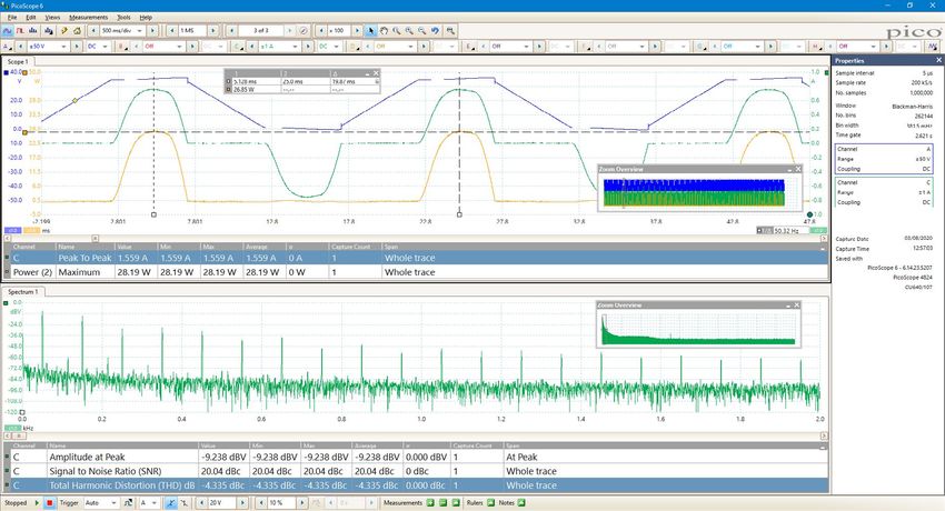
Up to 8 channels of high resolution
With the PicoScope 4000A Series providing a choice of either 2, 4 or 8 high-
resolution analog channels you can easily view audio, ultrasonic, vibration and
power waveforms, analyze timing of complex systems, and perform a wide range
of precision measurement tasks on multiple inputs at the same time. The scopes
have a small, compact footprint, yet the BNC connectors with a minimum 20 mm
spacing still accept all common probes and accessories.

Despite their compact size, there is no compromise on performance. With a high
vertical resolution of 12 bits, 20 MHz bandwidth, 256 MS buffer memory, and a
fast sampling rate of 80 MS/s, the PicoScope 4000A Series has the power and
functionality to deliver accurate results. With up to 8 channels, these oscilloscopes
can analyze multiple serial buses such as UART, I2C, SPI, CAN and LIN plus control
and driver signals.

Why choose the PicoScope 4000A Series oscilloscopes?                                         Suitable for a broad range of applications, including:
The PicoScope 4000A Series provides 20 MHz bandwidth, low noise, 12-bit resolution,          •   Power supply start sequencing
deep capture memory and an integrated function and arbitrary waveform generator in a         •   7-channel audio systems
compact USB 3 connected PC-based package, together with a proven user interface.             •   Multi-sensor systems
                                                                                             •   Multi-phase drives and controls
This series of oscilloscopes is especially suited to engineers, scientists and technicians   •   Predictive/preventive maintenance
working on a wide range of electrical, mechanical, audio, lidar, radar, ultrasonic, NDT      •   Complex embedded system development
and predictive maintenance systems who need to make precise measurements and                 •   Power harmonics analysis
analysis of repetitive or single-shot long-duration waveforms.                               •   Vibration analysis and diagnostics
The PicoScope 4000A Series is unlike conventional oscilloscopes with 8-bit resolution        •   Long-duration waveform capture
and limited capture memory or card-based digitizers that require an expensive                •   Lubricant analysis
mainframe and offers the following benefits:                                                 •   Acoustic emission analysis
                                                                                             •   Oil condition sensors
•   PicoScope 6 user interface with time- and frequency-domain waveform views                •   Machine monitoring
•   Automatic measurements of important waveform parameters on up to a million               •   Motor condition monitoring and motor current signature analysis
    waveform cycles with each triggered acquisition using DeepMeasure™                       •   Model-based voltage and current systems
•   Decoding of 18 popular industry serial bus standards.
•   An application programming interface that provides direct control of the hardware
•   Five years warranty included as standard

                                                                                                                                                   PicoScope® 4000A Series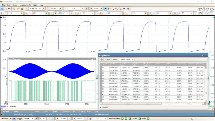
Power measurements
The PicoScope 4000A Series is ideal for making a range of power measurements on high voltages and currents and low-voltage control signals. For the best results, use a Pico
differential voltage probe (TA041 or TA057) in combination with a current clamp (TA167) or probes (TA167, TA325 or TA326). To improve the efficiency and reliability of power
designs, the scope can display and analyze standby power dissipation, inrush current, and steady-state power consumption. PicoScope’s built-in measurements and statistics of
parameters such as true RMS, frequency, peak‑to-peak voltage and THD allow accurate analysis of power quality.

Nonlinear loads and modern power-conversion equipment produce complex waveforms with significant harmonic content. These harmonics reduce efficiency by causing increased
heating in equipment and conductors, misfiring in variable speed drives, and torque pulsations in motors. The 12-bit PicoScope 4000A Series has the precision to measure
distortion typically up to the 100th harmonic. On the supply side, power quality issues such as sags and dips, swells and spikes, flicker, interruptions and long-term voltage and
frequency variations can also be checked for regulatory compliance.

In a 3-phase distribution system, it is important to characterize and balance loads across phases. With up to 8 channels, the PicoScope 4000A Series can monitor waveforms
of current and voltage on all 4 conductors of a 3-phase-plus‑neutral system. This helps to identify mismatches that can cause breaker tripping, or transformer and conductor
overheating.

                                                                                                                                                  PicoScope® 4000A Series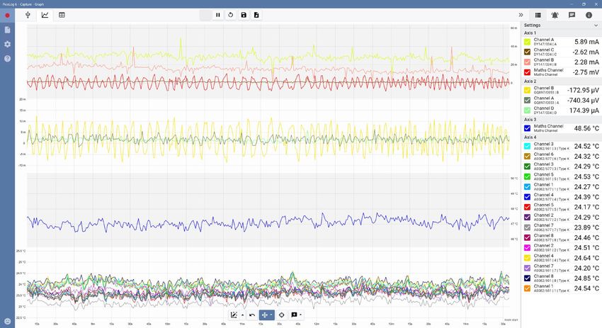
DeepMeasure™
One waveform, millions of measurements.

Measurement of waveform pulses and cycles is key to verification of the performance
of electrical and electronic devices. DeepMeasure delivers automatic measurements
of important waveform parameters, such as pulse width, rise time and voltage. Up to a
million cycles can be displayed with each triggered acquisition. Results can be easily
sorted, analyzed and correlated with the waveform display.

Complex embedded systems
When debugging an embedded system with a scope, you can quickly run out of channels.
You may need to look at an I2C or SPI bus at the same time as multiple power rails, DAC
outputs and logic signals. With up to eight channels, the PicoScope 4000A Series can
cope with all of this. Choose whether to decode up to eight serial buses, with analog
waveforms and decoded data both visible, or a combination of serial buses and other
analog or digital signals. PicoScope provides advanced triggering on all channels, so you
can search for runt pulses, dropouts and noise as well as looking for data patterns using
the 4-input Boolean logic trigger.

                                                                                            Split-screen display
                                                                                            The PicoScope 6 software can display up to 16 scope and spectrum
                                                                                            views at once, making comparisons and analysis even clearer. The
                                                                                            split-screen display can be customized to show whichever combination
                                                                                            of waveforms you need, to display multiple channels or different
                                                                                            variants of the same signal. Additionally, each waveform shown works
                                                                                            with individual zoom, pan, and filter settings for ultimate flexibility.
                                                                                            Alongside the facility to use monitors many times larger than a fixed
                                                                                            scope display, these are further reasons to choose a USB oscilloscope
                                                                                            over a traditional benchtop model.

                                                                                                                                   PicoScope® 4000A Series
PicoScope performance and reliability
With over 25 years’ experience in the test and measurement industry, we know
what’s important in an oscilloscope. The PicoScope 4000A Series delivers
value for money by including a wide range of high-end features as standard.
The PicoScope 6 software includes serial decoding and mask limit testing, and
new functionality is regularly delivered through free upgrades to ensure that
your device does not quickly become outdated. All Pico Technology devices
are optimized with the help of feedback from our customers.
Zoom in and capture every last detail
The PicoScope zoom function lets you take a closer look at the fine detail on
your signals. Using simple point-and-click tools you can quickly zoom in on both
axes and reveal every last detail of the signal, whilst the undo zoom function
lets you return to the previous view.
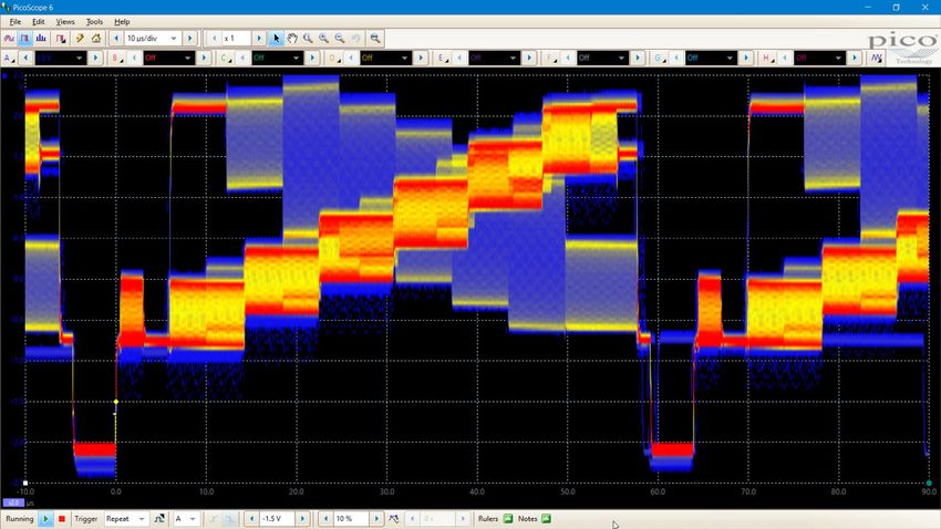
Color persistence modes
Advanced display modes allow you to see old and new data superimposed,
with new data in a brighter color or shade. This makes it easy to see glitches
and dropouts and to estimate their relative frequency. Choose between analog
persistence, digital color, or custom display modes.
PicoScope® 4000A Series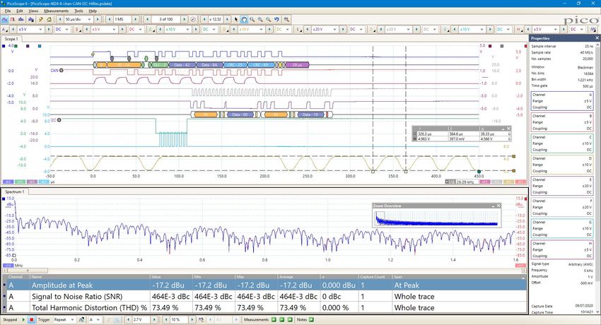
Math channels
With PicoScope 6 you can perform a variety of mathematical calculations on
your input signals and reference waveforms.

Use the built-in list for simple functions such as addition and inversion,
or open the equation editor and create complex functions involving
trigonometry, exponentials, logarithms, statistics, integrals and derivatives,
filters, averaging and peak-detection.

Spectrum analyzer
With the click of a button, you can open a new window to display a spectrum
plot of selected channels up to the full bandwidth of the oscilloscope. A
comprehensive range of settings gives you control over the number of
spectrum bands, window types and display modes.

A comprehensive set of automatic frequency-domain measurements can
be added to the display, including THD, THD+N, SINAD, SNR, SFDR and IMD.
You can even use the AWG and spectrum mode together to perform swept
scalar network analysis, and you can apply mask testing to the spectrum
display to speed up fault-finding.

                                                                                 PicoScope® 4000A Series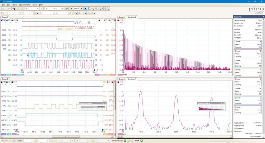
Automatic measurements
PicoScope allows you to display a table of automated measurements for troubleshooting and analysis: 15 scope and 11 spectrum mode measurements are available.

Using the built-in measurement statistics you can see the average, standard deviation, maximum and minimum of each measurement as well as the live value. You can add as
many measurements as you need on each view. Each measurement includes statistical parameters showing its variability. For information on the measurements available in
scope and spectrum modes, see Automatic Measurements in the Specifications table.

Scope mode measurements                                                                Spectrum mode measurements

Arbitrary waveform and function generators
In addition, all models in the PicoScope 4000A Series have a built-in low-
distortion, 80 MS/s, 14-bit arbitrary waveform generator (AWG), which can be
used to emulate missing sensor signals during product development, or to
stress-test a design over the full intended operating range. Waveforms can be
imported from data files or created and modified using the built-in graphical
AWG editor.
A function generator is also included, with sine, square, and triangle waves
up to 1 MHz, along with DC level, white noise, and many more standard
waveforms. As well as level, offset and frequency controls, advanced options
allow you to sweep over a range of frequencies. Combined with the spectrum
peak hold option, this creates a powerful tool for testing amplifier and filter
responses.

                                                                                                                                             PicoScope® 4000A Series
Serial decoding
The PicoScope 4000A Series includes serial decoding capability across all channels as standard. PicoScope software can decode 1-Wire, ARINC 429, CAN, DALI, DCC, DMX512,
Ethernet 10Base-T, FlexRay, I²C, I²S, LIN, Manchester, Modbus ASCII, Modbus RTU, PS/2, SENT, SPI, and UART protocol data as standard, with more protocols in development and
available in the future with free-of-charge software upgrades.

The decoded data can be displayed in the format of your choice: in graph, in table, or both at once.

• Graph format shows the decoded data beneath the waveform on a common time axis, with error frames marked in red. These frames can be zoomed to investigate noise or
distortion.

• Table format shows a list of the decoded frames, including the data and all flags and identifiers. You can set up filtering conditions to display only the frames you are interested
in, search for frames with specified properties, or define a start pattern to signal when the program should list the data.

PicoScope can also import a spreadsheet to decode the hexadecimal data into user-defined text strings.

                                                                                                                                                     PicoScope® 4000A Series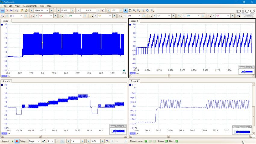
High signal integrity
Careful front-end design and shielding reduce noise, crosstalk and harmonic distortion, meaning we are proud
to publish the specifications for our scopes in detail. Decades of oscilloscope design experience can be seen in
improved pulse response and bandwidth flatness, and low distortion. The scope features 12 input ranges from
±10 mV to ±50 V full scale and a huge spurious free dynamic range of up to 70 dB. The result is simple: when you
probe a circuit, you can trust in the waveform you see on the screen.

High-end features as standard
Buying a PicoScope is not like making a purchase from other oscilloscope companies, where optional extras considerably increase the price. With our scopes, high-end features
such as resolution enhancement, mask limit testing, serial decoding, advanced triggering, automatic measurements, math channels, XY mode, segmented memory, and a signal
generator are all included in the price.

To protect your investment, both the PC software and firmware inside the scope can be updated. Pico Technology has a long history of providing new features for free through
software downloads. We deliver on our promises of future enhancements year after year, unlike many other companies in the field. Users of our products reward us by becoming
lifelong customers and frequently recommending us to their colleagues.

                                                                                USB connectivity
                                                                                The SuperSpeed USB 3.0 connection not only allows high-speed data acquisition and transfer, but
                                                                                also makes printing, copying, saving, and emailing your data from the field quick and easy. USB
                                                                                powering removes the need to carry around a bulky external power supply, making the kit even
                                                                                more portable for the engineer on the move.

                                                                                The Software Development Kit (SDK) allows unlimited data collection and fast streaming.

                                                                                                                                                PicoScope® 4000A Series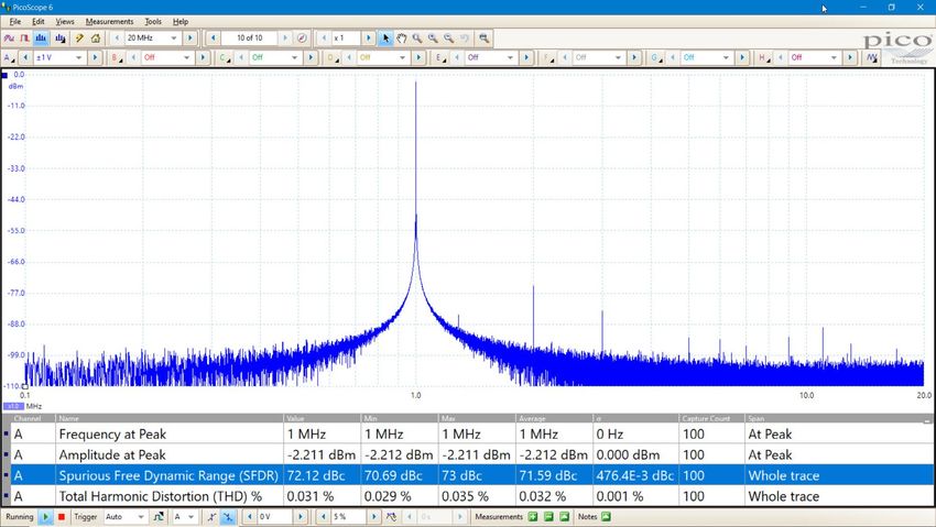
Digital triggering
Most digital oscilloscopes still use an analog trigger architecture based on comparators.
This can cause time and amplitude errors that cannot always be calibrated out. The use of
comparators often limits the trigger sensitivity at high bandwidths and can also create a
long trigger rearm delay.

In 1991 Pico set an innovation milestone by pioneering the use of full digital triggering
using the actual digitized data. This reduces trigger errors and allows our oscilloscopes
to trigger on the smallest signals, even at the full bandwidth. All real-time triggering is
digital, resulting in high threshold resolution with programmable hysteresis and optimal
waveform stability.

The reduced rearm delay provided by digital triggering, together with segmented memory,
allows the capture of events that happen in rapid sequence. At the fastest timebase, rapid
triggering can capture a new waveform every 3 microseconds until the buffer is full.

                                                                                              Advanced triggers
                                                                                              As well as the standard range of triggers found on most oscilloscopes, the
                                                                                              PicoScope 4000A Series has a comprehensive set of advanced triggers built in to help
                                                                                              you capture the data you need. These include pulse width, windowed, and dropout triggers
                                                                                              to help you find and capture your signal quickly.

                                                                                                                                                      PicoScope® 4000A Series
Mask limit testing
PicoScope allows you to draw a mask around any signal, in either the scope view or the spectrum view, with user-defined tolerances. This has been designed specifically for
production and debugging environments, enabling you to compare signals. Simply capture a known good signal, draw a mask around it, and then attach the system under test.
PicoScope will capture any intermittent glitches and can show a failure count and other statistics in the Measurements window.
The numerical and graphical mask editors can be used separately or in combination, allowing you to enter accurate mask specifications, modify existing masks, and import and
export masks as files.
Alarms
PicoScope can be programmed to execute actions when certain events occur. The events
that can trigger an alarm include mask limit fails, trigger events and buffers full. The actions
that PicoScope can execute include saving a file, playing a sound, executing a program and
triggering the signal generator or the AWG. Alarms, coupled with mask limit testing, help
create a powerful and time-saving waveform monitoring tool. Capture a known good signal,
auto-generate a mask around it and then use the alarms to automatically save any waveform
(complete with a time/date stamp) that does not meet specification.
PicoScope® 4000A SeriesDigital low-pass filtering
Each input channel has its own digital low-pass filter with independently adjustable cut-
off frequency from 1 Hz to the full bandwidth of the scope. This enables you to reject
noise on selected channels while viewing high‑bandwidth signals on the others.
Custom probe settings
The custom probes menu allows you to correct for gain, attenuation, offsets and nonlinearities
of probes and transducers, or convert to different measurement units. Definitions for standard
Pico-supplied probes are built in, and you can also create your own using linear scaling or even an
interpolated data table, and save them to disk for later use.
PicoScope® 4000A SeriesPicoScope 6 software Tools: Including Trigger Waveform replay tools: Zoom and pan tools: Rulers: Each axis has two rulers
serial decoding, marker: Drag PicoScope 6 automatically PicoScope 6 allows a zoom that can be dragged across
The display can be as simple or as
reference channels, the yellow records up to 10 000 of the factor of several million, the screen to make quick
advanced as you need. Begin with macro recorder, diamond to most recent waveforms. which is necessary when measurements of amplitude,
a single view of one channel, and alarms, mask limit adjust trigger You can quickly scan working with the deep time and frequency.
then expand the display to include testing and math level and pre- through to look for memory of the PicoScope
any number of live channels, math channels. trigger time. intermittent events, or use 4000A Series oscilloscopes.
channels and reference waveforms. the Buffer Navigator to
search visually. Signal generator:
Generates standard
signals or arbitrary
Auto setup button:
waveforms.
Configures the collection
Includes frequency
time and voltage range for
sweep mode.
clear display of signals.
Properties sheet:
Channel options: Shows a summary
Filtering, offset, resolution of the settings that
enhancement, custom PicoScope is using.
probes and more.
Ruler legend:
Oscilloscope controls: Absolute and
Controls such as voltage differential ruler
range, scope resolution, measurements are
channel enable, timebase listed here.
and memory depth.
Views: PicoScope
Movable axes: The 6 is carefully
vertical axes can be designed to make
scaled and dragged up the best use of
or down. This feature the display area.
is particularly useful You can add new
when one waveform scope, spectrum
is obscuring another. and XY views
There’s also an Auto with automatic or
Arrange Axes command. custom layouts.
Trigger toolbar: Quick Automatic measurements: Display calculated Zoom overview: Click and
access to main controls, measurements for troubleshooting drag for quick navigation
with advanced triggers in a and analysis. You can add as many in zoomed views.
pop-up window. measurements as you need on each view.
Each measurement includes statistical
parameters showing its variability.
PicoScope® 4000A SeriesPicoSDK - write your own apps
Our free software development kit, PicoSDK, allows you to write your own software and includes drivers for Windows, macOS and Linux. Example code supplied on our GitHub
organization page shows how to interface to third-party software packages such as National Instruments LabVIEW and MathWorks MATLAB.
PicoSDK supports data streaming, a mode that captures gap-free continuous data over USB 3.0 direct to the PC’s RAM or hard disk, at a rate of up to 80 MS/s on one channel (up to
160 MS/s split between multiple channels), so you are not limited by the size of the scope’s buffer memory. Sampling rates in streaming mode are subject to PC specifications and
application loading.
There is also an active community of PicoScope users who share both code and whole applications on our Test and Measurement Forum and the PicoApps section of the website.
The Frequency Response Analyzer shown here is a popular application on the forum.
Copyright © 2014-2021 Aaron Hexamer. Distributed under GNU GPL3.
PicoScope® 4000A SeriesPicoLog 6 software
The PicoScope 4000A Series oscilloscopes are also
supported by the PicoLog 6 data logging software, allowing
you to view and record signals on multiple units in one
capture.
PicoLog 6 allows sample rates of up to 1 kS/s per
channel, and is ideal for long-term observation of general
parameters, such as voltage or current levels, on several
channels at the same time, whereas the PicoScope 6
software is more suitable for waveshape or harmonic
analysis.
You can also use PicoLog 6 to view data from your
oscilloscope alongside a data logger or other device. For
example, you could measure voltage and current with your
PicoScope and plot both against temperature using a
TC-08 thermocouple data logger, or humidity with a DrDAQ
multipurpose data logger.
PicoLog 6 is available for Windows, macOS, Linux and
Raspberry Pi OS.
Pack contents
• PicoScope 4000A Series 2-, 4- or 8-channel oscilloscope
• Oscilloscope probes
• USB 3.0 cable 1.8 m
• Quick Start Guide
PicoScope® 4000A SeriesPicoScope 4000A Series specifications
PicoScope 4224A PicoScope 4424A PicoScope 4824A
Vertical
Input channels 2 4 8
Connector type BNC
20 MHz (50 mV to 50 V ranges)
Bandwidth (−3 dB)
10 MHz (10 mV and 20 mV ranges)
17.5 ns (50 mV to 50 V ranges)
Rise time (calculated)
35.0 ns (10 mV and 20 mV ranges)
Vertical resolution 12 bits
Software-enhanced vertical resolution Up to 16 bits
Input type Single-ended
Input ranges ±10 mV to ±50 V full scale, in 12 ranges
Input sensitivity 2 mV/div to 10 V/div (10 vertical divisions)
Input coupling AC / DC
Maximum input voltage ±50 V DC / 42.4 V pk max AC
Input characteristics 1 MΩ ∥ 19 pF
DC accuracy ±(1% of full scale + 300 µV)
±250 mV (10 mV to 500 mV ranges)
Analog offset range
±2.5 V (1 V to 5 V ranges)
(vertical position adjustment)
±25 V (10 V to 50 V ranges)
Analog offset control accuracy ±1% of offset setting additional to basic DC accuracy
Overvoltage protection ±100 V (DC + AC peak)
Horizontal timebase
80 MS/s (up to four channels in use)
Maximum sampling rate (real-time)
40 MS/s (five or more channels in use)
20 MS/s using PicoScope 6 software, shared between channels
Maximum sampling rate (USB 3.0 streaming)
80 MS/s max. for a single channel using PicoSDK. 160 MS/s total across all channels. (PC-dependent)
Timebase ranges (real-time) 20 ns/div to 5000 s/div
Buffer memory (shared between active channels) 256 MS
Buffer memory (streaming mode) 100 MS in PicoScope software. Up to available PC memory when using PicoSDK
10 000 segments (rapid block mode)
Waveform buffer
10 000 waveforms (PicoScope 6 circular buffer)
Timebase accuracy ±20 ppm (+5 ppm/year)
Sampling jitter 25 ps RMS typical
PicoScope® 4000A SeriesPicoScope 4224A PicoScope 4424A PicoScope 4824A
Dynamic performance (typical)
Crosstalk (full bandwidth) −76 dB
< −60 dB, 10 mV range
Harmonic distortion
< −70 dB, 20 mV and higher ranges
> 60 dB, 20 mV and 10 mV ranges
SFDR
> 70 dB, 50 mV and higher ranges
Noise 45 μV RMS on 10 mV range
Pulse response < 1% overshoot
Bandwidth flatness DC to full bandwidth (+0.2 dB, −3 dB)
Triggering
Source All channels
Trigger modes None, auto, repeat, single, rapid (segmented memory)
Trigger types Rising or falling edge
Advanced trigger types Simple edge, advanced edge, window, pulse width, interval, window pulse width, level dropout, window dropout, runt
Trigger sensitivity Digital triggering provides 1 LSB accuracy up to full bandwidth
Pre-trigger capture Up to 100% of capture size
Post-trigger delay Zero to 4 billion samples (settable in 1 sample steps)
Trigger rearm time < 3 μs on fastest timebase
Maximum trigger rate Up to 10 000 waveforms in a 30 ms burst
Advanced digital trigger levels All trigger levels, window levels and hysteresis values settable with 1 LSB resolution across input range
Advanced digital trigger time intervals All time intervals settable with 1 sample resolution from 1 sample (minimum 12.5 ns) up to 4 billion sample intervals
Function generator
Standard output signals Sine, square, triangle, DC voltage, ramp up, ramp down, sinc, Gaussian, half-sine.
White noise, selectable amplitude and offset within output voltage range
Pseudorandom output signals Pseudorandom binary sequence (PRBS), selectable high and low levels within output voltage range, selectable bit rate up to
1 Mb/s
Standard signal frequency 0.03 Hz to 1 MHz
Output frequency accuracy ±20 ppm
Output frequency resolution < 0.02 Hz
Sweep modes Up, down, dual with selectable start/stop frequencies and increments
You can trigger a counted number of waveform cycles or sweeps (from 1 to 1 billion) from the scope trigger or manually from
Triggering
software.
Output voltage range ±2 V
Output voltage adjustment Signal amplitude and offset are adjustable in approximately 300 µV steps, within an overall ±2 V range.
DC accuracy ±1% of full scale
Amplitude flatness < 0.5 dB to 1 MHz, typical
SFDR 87 dB typical
Output resistance 600 Ω
Connector type Rear-panel BNC
Overvoltage protection ±10 V
PicoScope® 4000A SeriesPicoScope 4224A PicoScope 4424A PicoScope 4824A
Arbitrary waveform generator
Update rate 80 MS/s
Buffer size 16 k samples
Vertical resolution 14 bits (output step size approximately 300 µV)
Bandwidth 1 MHz
Rise time (10% to 90%) 150 ns
Sweep modes, triggering, frequency accuracy and resolution, voltage range and accuracy and output characteristics as for function generator.
Spectrum analyzer
Frequency range DC to 20 MHz
Display modes Magnitude, average, peak hold
Y axis Logarithmic (dbV, dBu, dBm, arbitrary dB) or linear (volts)
X axis Linear or logarithmic
Windowing functions Rectangular, Gaussian, triangular, Blackman, Blackman−Harris, Hamming, Hann, flat-top
Number of FFT points Selectable from 128 to 1 million in powers of 2
Math channels
−x, x+y, x−y, x*y, x/y, x^y, sqrt, exp, ln, log, abs, norm, sign, sin, cos, tan, arcsin, arccos, arctan, sinh, cosh, tanh, delay, average,
Functions
frequency, derivative, integral, min, max, peak, duty, highpass, lowpass, bandpass, bandstop
Operands A to B, D or H (input channels), T (time), reference waveforms, pi, constants
Automatic measurements
AC RMS, cycle time, DC average, duty cycle, edge count, fall time, falling edge count, falling rate, frequency, high pulse width,
Scope mode
low pulse width, maximum, minimum, negative duty cycle, peak-to-peak, rise time, rising edge count , rising rate, true RMS
Frequency at peak, amplitude at peak, average amplitude at peak, total power, THD %, THD dB, THD+N, SFDR, SINAD, SNR,
Spectrum mode
IMD
Statistics Minimum, maximum, average, standard deviation
DeepMeasure™
Cycle number, cycle time, frequency, low pulse width, high pulse width, duty cycle (high), duty cycle (low), rise time, fall time,
Parameters
undershoot, overshoot, max. voltage, min. voltage, voltage peak to peak, start time, end time
Serial decoding
1-Wire, ARINC 429, CAN, DALI, DCC, DMX512, Ethernet 10Base-T, FlexRay, I²C, I²S, LIN, Manchester, Modbus ASCII, Modbus
Protocols
RTU, PS/2, SENT, SPI, UART (subject to number of channels available)
Mask limit testing
Statistics Pass/fail, failure count, total count
Mask creation User-drawn, table entry, auto-generated from waveform or imported from file
Display
Interpolation Linear or sin(x)/x
Persistence modes Digital color, analog intensity, custom, fast
Output
File formats bmp, csv, gif, animated gif, jpg, mat, pdf, png, psdata, pssettings, txt
Functions Save, copy to clipboard, print
PicoScope® 4000A SeriesPicoScope 4224A PicoScope 4424A PicoScope 4824A
General
USB 3.0 SuperSpeed
PC connectivity
USB 2.0 Hi-Speed compatible
PC connector type USB 3.0 type B
Processor, memory and disk space: as required by the operating system
PC requirements
Ports: USB 3.0 (recommended) or 2.0 (compatible)
Power requirements Powered from USB
Ground terminal M4 screw terminal, rear panel.
Dimensions 190 x 170 x 40 mm (including connectors)
Weight 0.55 kg
Operating: 0 °C to 45 °C (20 °C to 30 °C for stated accuracy)
Temperature range
Storage: −20 °C to +60 °C.
Operating: 5% to 80% RH non-condensing
Humidity range
Storage: 5% to 95% RH non-condensing.
Altitude range Up to 2000 m
EN 61010 pollution degree 2: “only nonconductive pollution occurs except that occasionally a temporary conductivity caused
Pollution degree
by condensation is expected”
Safety compliance Designed to EN 61010-1; LVD compliant
EMC compliance Tested to meet EN 61326-1 and FCC Part 15 Subpart B.
Environmental compliance RoHS and WEEE
Warranty 5 years
Software
Windows software (32-bit or 64-bit)* PicoScope 6, PicoLog 6, PicoSDK
macOS software (64-bit)* PicoScope 6 Beta (including drivers), PicoLog 6 (including drivers)
PicoScope 6 Beta software and drivers, PicoLog 6 (including drivers)
Linux software (64-bit)*
See Linux Software and Drivers to install drivers only
PicoLog 6 (including drivers)
Raspberry Pi 4B (Raspberry Pi OS)*
See Linux Software and Drivers to install drivers only
* See the picotech.com/downloads page for more information.
Chinese (simplified), Chinese (traditional), Czech, Danish, Dutch, English, Finnish, French, German, Greek, Hungarian, Italian,
Languages supported, PicoScope 6
Japanese, Korean, Norwegian, Polish, Portuguese, Romanian, Russian, Spanish, Swedish, Turkish
Languages supported, PicoLog 6 Simplified Chinese, Dutch, English (UK), English (US), French, German, Italian, Japanese, Korean, Russian, Spanish
PicoScope® 4000A SeriesPicoScope 4000A Series inputs and outputs
PicoScope 4224A
Input channels A and B
PicoScope 4424A
Input channels A to D
PicoScope 4824A
Input channels A to H
Rear panel
Function generator and USB port
arbitrary waveform generator output Ground terminal
PicoScope® 4000A SeriesOrdering information
Order code Description USD* EUR* GBP*
PQ288 PicoScope 4224A 2-channel 20 MHz oscilloscope kit with 2 TA375 probes 899 759 629
PQ289 PicoScope 4424A 4-channel 20 MHz oscilloscope kit with 4 TA375 probes 1425 1205 999
PQ290 PicoScope 4824A 8-channel 20 MHz oscilloscope kit with 4 TA375 probes 2585 2195 1815
Optional accessories
TA375 100 MHz 1:1/10:1 passive switchable probe 25 21 17
TA041 25 MHz 10:1/100:1 active differential probe, ±700 V CAT III 379 319 269
TA057 25 MHz 20:1/200:1 active differential probe, ±1400 V CAT III 379 319 269
TA044 70 MHz 100:1/1000:1 differential probe, ±7000 V 919 779 639
PS008 Optional power supply for TA041 and TA057 probes 25 21 18
TA167 2000 A AC/DC current clamp 259 219 185
PP877 Three-axis accelerometer and oscilloscope interface 409 349 289
PP969 Carry case 81 69 56
Calibration service
Order code Description USD* EUR* GBP*
CC028 Calibration certificate for the PicoScope 4000A Series oscilloscopes 129 109 95
* Prices correct at time of publication. Sales taxes not included. Please contact Pico Technology for the latest prices before ordering.
United Kingdom global headquarters North America regional office Asia-Pacific regional office
Pico Technology Pico Technology Pico Technology
James House 320 N Glenwood Blvd Room 2252, 22/F, Centro
Colmworth Business Park Tyler 568 Hengfeng Road
St. Neots TX 75702 Zhabei District
Cambridgeshire United States Shanghai 200070
PE19 8YP PR China
United Kingdom
www.picotech.com www.picotech.com www.picotech.com
+44 (0) 1480 396 395 +1 800 591 2796 +86 21 2226-5152
sales@picotech.com sales@picotech.com pico.asia-pacific@picotech.com
Errors and omissions excepted.
Pico Technology, PicoScope, PicoLog and PicoSDK are internationally registered trademarks of Pico Technology Ltd.
www.picotech.com
LabVIEW is a trademark of National Instruments Corporation. Linux is the registered trademark of Linus Torvalds, registered in the U.S. and
other countries. macOS is a trademark of Apple Inc., registered in the U.S. and other countries. MATLAB is a registered trademark of The
MathWorks, Inc. Windows is a registered trademark of Microsoft Corporation in the United States and other countries.
MM116.en-4 Copyright © 2016–2021 Pico Technology Ltd. All rights reserved.
Pico Technology @LifeAtPico @picotechnologyltd Pico Technology @picotechYou can also read