On-shot spatiotemporal laser wavefront characterization via wavelength-multiplexed holography for precision control of high-intensity laser plasma ...
←
→
Page content transcription
If your browser does not render page correctly, please read the page content below
On-shot spatiotemporal laser wavefront characterization
via wavelength-multiplexed holography for precision
control of high-intensity laser plasma interactions

 y

 x

HEDS Center Seminar
 z Elizabeth S. Grace
February 9, 2023
Ultrafast laser pulse measurements are needed to truly
understand the target physics and to have predictive
capability.
▪ Characterization of the complete 4D
 electric field E(x,y,z,t) of the short-
 pulse (
This talk covers advances in high-precision laser
electric field measurements and control.

High-intensity, on-
shot laser electric
field measurement

Temporal
structuring for
optimization of
laser-driven particle
sources

Spatiotemporal
structuring of laser
intensity and phase
to generate optical
vortices

 3
This talk covers advances in high-precision laser
electric field measurements and control.

High-intensity, on-
shot laser electric 1
field measurement

Temporal 2
structuring for
 y(mm)

optimization of 3
laser-driven particle
sources
 4
Spatiotemporal
structuring of laser 5
intensity and phase
to generate optical 6
vortices 1 2 3 4 5 6
 Data from Ti:Sapp oscillator at GT x (mm)

 4
This talk covers advances in high-precision laser
electric field measurements and control.

High-intensity, on-
shot laser electric
field measurement

Temporal
structuring for
optimization of
laser-driven particle
sources

Spatiotemporal
structuring of laser
intensity and phase
to generate optical
vortices

 Data from CSU laser system (2021).

 5
This talk covers advances in high-precision laser
electric field measurements and control.

 λ
High-intensity, on-
shot laser electric
field measurement

Temporal
structuring for
optimization of
laser-driven particle
sources

Spatiotemporal
structuring of laser
intensity and phase
to generate optical
vortices

 Simulation by E. Grace

 6
Thank you to my collaborators!

 UCSD LLNL CSU
Joohwan Kim Blagoje Djordjevic Ghassan Zeraouli
 Matt Hill
 Andrew Longman
 Tammy Ma
 Derek Mariscal
 Graeme Scott
 Raspberry Simpson
 Georgia Tech Brent Stuart
Rick Trebino Kelly Swanson
 Scott Wilks
 Jackson Williams

 7
High-intensity laser-plasmas form the basis for many
 interdisciplinary applications.

 Proton Radiography Laboratory Astrophysics Neutron Radiography Electron Acceleration

Ma cki nnon et al, RSI (2004). MPIA/NASA/Ca lar Al to Observatory Johnson et al, MRP 15 58-66 (2020) La boratoire d’Optique Appliquée

 Ion Acceleration X-Ray Radiography Medical Radiotherapy Stress Testing

Ma cchi , et al., Rev. Mod. Phys ., 85 (2013) Wi l helm Röntgen, 1895 Va ri an Vi talbeam Ba rberio et al Na ture (2018)

 8
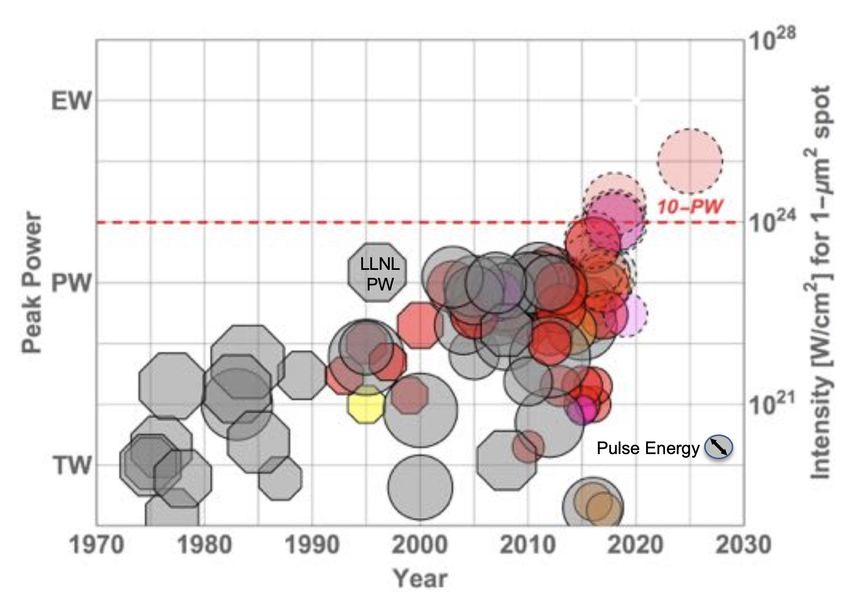
Around the world, investment in laser technology has
produced increased peak powers.

 Accurate laser characterization is crucial for every single
 one of these high-power laser systems but remains a gap. 9
Livermore is the leader in developing high peak power
lasers, and characterization of these lasers is crucial for
HED science and other applications.

NIF

 JLF

 HAPLS
 Omega EP

 Research with short-pulse lasers is a large part of the HED
 work at LLNL, from developing predictive capability at ARC
 to applications like secondary sources.
 10
High-intensity, on-shot laser electric field measurement
is crucial.

High-intensity, on-
shot laser electric 1
field measurement

Temporal 2
structuring for
 y(mm)

optimization of 3
laser-driven particle
sources
 4
Spatiotemporal
structuring of laser 5
intensity and phase
to generate optical 6
vortices 1 2 3 4 5 6
 Data from Ti:Sapp oscillator at GT x (mm)

 11
Every ultrafast laser pulse exhibits complex
 spatiotemporal couplings that are usually not diagnosed.
 Pulse-Front Tilt Spatial Chirp Angular Dispersion
 x

 θ

 t

 , ∝ exp( 2 + 2 − 2 ) , ∝ exp( 2 + 2 − 2 ) , ∝ exp( 2 + 2 − 2 )
 ≠ 0 ≠ 0 ≠ 0

 Wavefront rotation Wavefront-tilt dispersion Ultrafast Lighthouse Effect

 x
 θ

 t

 , ∝ exp( 2 + 2 − 2 ) , ∝ exp( 2 + 2 − 2 ) , ∝ exp( 2 + 2 − 2 )
 ≠ 0 ≠ 0 ≠ 0
*S. Akturk et al., 13 21 (2005).
 12
This pulse has temporal chirp, pulse-front tilt, and
 .

 1

 2
 y(mm)

 3

 4

 5

 6
 1 2 3 4 5 6
 x (mm)

 *P. Gabolde and R. Trebino, J. Opt. Soc. Am. B 25 A25 (2008) 13
Spatiotemporal distortions can be very detrimental to
 applications due to reduced focal spot intensity.

* Z. Guang et al. JOSAB 3:1955-1962(2016). *P. Bowlan et al., Opt. Express 16 18 (2008).
 14
Existing pulse measurement techniques generally
measure pulses in time only.

▪ For example, Frequency Resolved Optical Gating (FROG) and its cousin,
 GRENOUILLE, both capture the intensity and phase of the pulse in time (but
 averaged over space):

▪ This is fine if E(x,y,t) = E(x,y)E(t). But the spatial and temporal dependencies
 may not separate like this.

▪ Single-shot FROG and GRENOUILLE can also provide first order space-time
 couplings in one direction, but complete spatiotemporal measurement is
 needed.

 15
Spatiotemporal diagnostics are needed for the whole
picture.

▪ The full spatiotemporal dependencies are written out:

▪ To measure these fields, we require a complete spatiotemporal pulse-
 measurement device.

▪ Due to low rep rates in high-power systems and laser instabilities, we also
 require single-shot measurement.

▪ STRIPED FISH solves this problem by taking single-shot complete
 spatiotemporal pulse measurements.

 16
Holography for Single-Shot Spatial and Temporal
 Measurement
 Spatially uniform,
 monochromatic
Measure the integrated reference beam

intensity I(x,y) of the sum of
known and unknown
monochromatic beams.

Extract the unknown
monochromatic field E(x,y)
from the cross term. Camera

 , Object
= , + , Unknown
 beam
+ , ( , ) cos , − ( , )

 Holography can provide the wavefront of the laser pulse.
 17
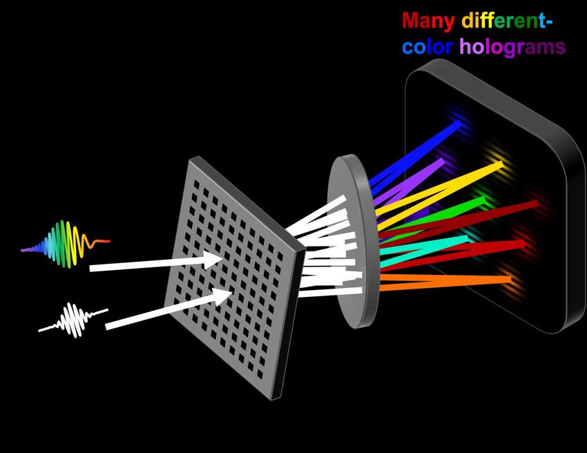
Spatially and Temporally Resolved Intensity and Phase
 Evaluation Device: Full Information from a Single
 Hologram (STRIPED FISH)

 By spectrally resolving the holograms, we obtain the
 wavefront at each frequency present in the laser pulse. 18
Gabolde et al, JOSAB (2008).
Theoretical STRIPED FISH trace for a simple pulse

False color indicates frequency 19
The STRIPED FISH retrieval algorithm yields the
complete pulse spatio-spectral field.

 Intensity
 and phase
 vs. (x,y,λ)

 *P. Gabolde and R. Trebino, J. Opt. Soc. Am. B 25 A25 (2008) 20
STRIPED FISH can measure laser pulses ranging from
 fs to 10 ps

 Temporal resolution is
 Spatial resolution
 limited by the frequency
 and range are
 separation of the
 limited by the
 holograms.
 camera.

The temporal range is limited by the spectral resolution of the bandpass filter.
Temporal range can be significantly increased if multiple delays are used, but
no longer single shot.

 21
What can be seen directly from the STRIPED FISH
 trace?
 Undistorted pulse

 Spatial chirp
 Re[(x-y,⍵)]

 Wavefront tilt dispersion
 Im[(x-y,⍵)]

 Re[(x-y,⍵)]
 + +
 Im[(x-y,⍵)]

*E. Grace et al., “Rapid retrieval of first-order spatiotemporal distortions for ultrashort laser pulses,” 22
Plas. Phys. Control. Fus. 63(12): 124005 (2021)
Reading these changes directly from the trace also
results in a rapid algorithm for high repetition rate
feedback.
 These plots show the retrieval performance for different
 coupling strengths, as described by the scalar ⍴.

 Due to the interrelation of spatiotemporal couplings, for collimated beams, the rest
 of the first-order spatiotemporal couplings can be calculated from these values.
 The retrieval algorithm rapidly provides the same first-order information as the
 complex 4-D retrieval provides with
The first on-shot full-power spatiotemporal
 measurement was taken at the Jupiter Laser Facility’s
 COMET laser. 28 shots were taken over one day.

 COMET: Compact
 Multipulse Terawatt
 Repetition rate: 15
 shots / hour
 Max energy on target:
 ~10 J
 Short pulse length: 1ps

*E. Grace et al., “Single-Shot Complete Spatiotemporal Measurement of Terawatt
Laser Pulses,” J. Opt. (2021).

 24
Raw single-pulse data of COMET short pulse at max
available intensity (0.3J – during maintenance phase)

Calibration (reference) trace Data Taken On-Shot

 25
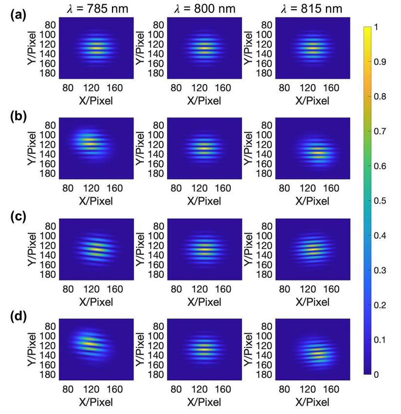
STRIPED FISH provides the spatial-spectral intensity
 and phase (and does so directly).

 = 1050 nm = 1052 nm = 1054 nm
Intensity
Phase

 26
The retrieved movie shows spatiotemporal complexity.

 27
Trends in COMET’s spatiotemporal couplings across all
 28 shots emerged.

 (x,t): Pulse (x,⍵): Spatial
 front tilt chirp

(kx,t): Ultrafast (kx,⍵): Angular
lighthouse dispersion

 The shear (red line) was extracted from these plots and fit to a polynomial,
 separating the first-order and higher-order contributions to the coupling.

 28
The temporal and spectral phase plots vs. x provide the
arrival time delay and frequency gradient.

For a single shot, the
temporal and spectral
phase curves are plotted
for several x positions.
 x

 x

 x

 29
Keep in mind: a linear spectral phase is a delay in time.
Similarly, a linear temporal phase is a frequency shift.

 ∆⍵

So, a change in slope of the linear temporal phase across x indicates that the
center frequency is moving across x.
 30
From this relationship, the temporal and spectral phase
plots vs. x provide the arrival time delay and frequency
gradient.
For a single shot, the
temporal and spectral
phase curves are plotted
for several x positions.
 x

 x

 So, a change in slope of x
 the linear phase across
 x means that the center
 frequency is moving
 across x.

 31
From this relationship, the temporal and spectral phase
plots vs. x provide the arrival time delay and frequency
gradient.
 For all shots, the arrival time
For a single shot, the delay and frequency gradient are
temporal and spectral extracted from the phase curves.
phase curves are plotted
for several x positions.
 x

 x

 So, a change in slope of x
 the linear phase across
 x means that the center
 frequency is moving
 across x.

 32
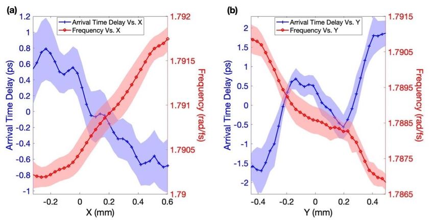
Arrival time delay and frequency vs. space are extracted
from the phase plots for both transverse dimensions.
 Error envelope indicates the shot-to-shot fluctuation in that value.
 All shots taken on the same day.

 The phase curves provide these plots for pulse front tilt and
 spatial chirp for all shots, which corroborate the shear plots.

 33
These distortions varied shot-to-shot.

 λ(x,y): Center frequency vs. position
 Red clusters
 on the right

 λ(nm)
 Blue clusters
 on the left

 Shot-to-shot variations cannot be captured by multi-shot methods, which must
 assume shot-to-shot stability. STRIPED FISH uniquely provides this measurement. 34
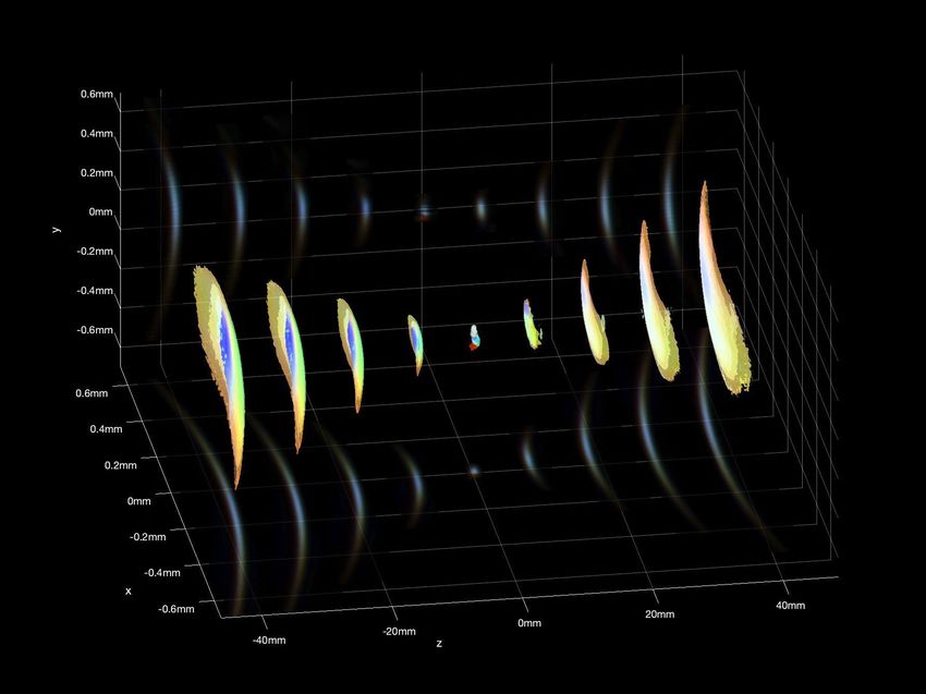
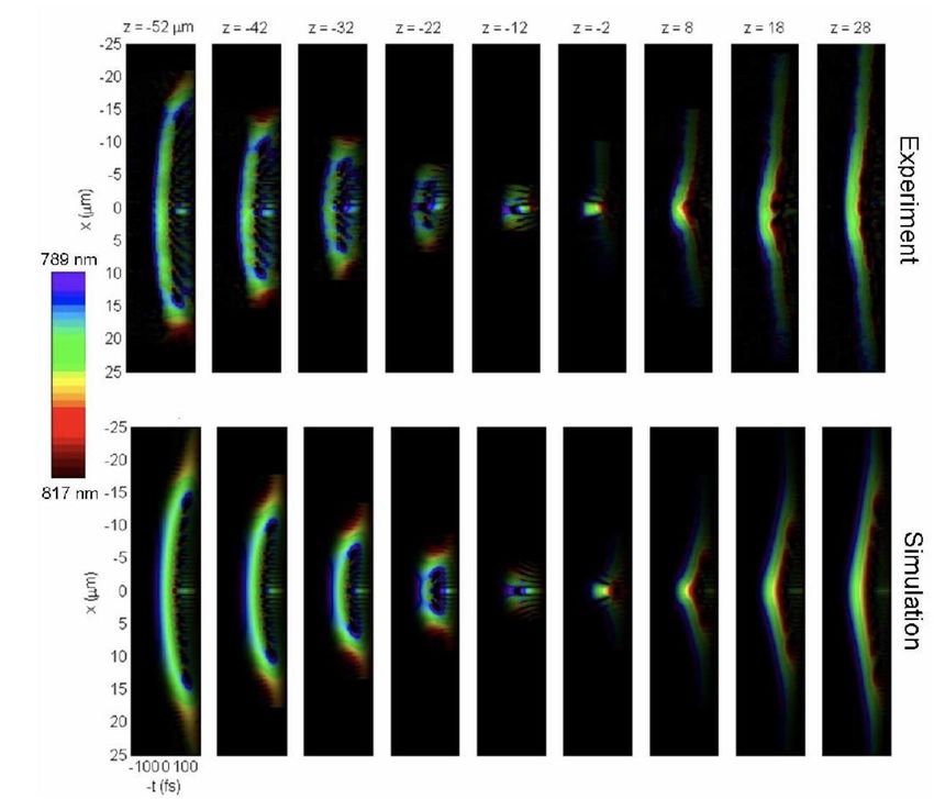
So far, we have seen the field at the STRIPED FISH
measurement plane. But what about the focus?

▪ Because STRIPED FISH provides such complete information about the pulse, the
 measurement can be used to obtain the complete electric field at the focus as well.

▪ STRIPED FISH uniquely provides the complete information E(x,y,t) required to
 propagate the pulse in the z-direction.

▪ Angular-spectrum diffraction integrals are used to propagate the pulse.

 Measured and propagated Simulated

 STRIPED FISH can also be used to obtain the electric field at the focus.

 35
Angular-spectrum diffraction integrals propagate the
electric field to the focus.

 From the movie at the measurement plane, we can extrapolate to any z-location.

 36
The electric field at any point in the z-direction can then
be extracted and plotted.

 Since the laser electric field is what creates and drives the plasma,
 37
 the field at the focus can be used as input for simulation codes.
Based on these measurements, we worked with JLF
 staff to correct the linear effects.

We tracked down the misalignment to
the diffraction grating in the
compressor and corrected the first-
order alignment.

 38
The NIF’s Advanced Radiographic Capability (ARC)
 laser already boasts an impressive set of laser
 diagnostics.
Existing diagnostics on ARC

 FROG traces for a 1 ps shot
 Linear
 Linear Scale Scale Measured
 Measured 10
 5
 FROG field FROGxfield Measured 5
 Linear
 Linear Scale
 x 10 Scale FROG
 Retrieved Retrieved Retrieved
 5
 field FROGxfield
 10
 5
 x 10 |Retrieved -|Retrieved
 Measured| - Measured|x 104 x 10
 4

 528 528 2 2 528 528 2 ARC is already equipped with 2528 528
 2.5 2.5

 527.5 527.5 1.5 1.5
 527.5 527.5 FROG, which provides the
 1.5 1.5
 527.5 527.5 2 2

 wavelength (nm)

 wavelength (nm)

 wavelength (nm)
 wavelength (nm)

 wavelength (nm)

 wavelength (nm)
 527 527 1 1 527 527
 spectral phase for STRIPED
 1 1527 527
 1.5 1.5

 FISH. 1 1

 526.5 526.5 0.5 0.5
 526.5 526.5 0.5 0.5
 526.5 526.5
 0.5 0.5

 526 526 526 526 526 526
 -5 0-5 50 5 -5 0-5 50 5 -5 0-5 50 5
 tim e (ps) tim e (ps) tim e (ps) tim e (ps) tim e (ps) tim e (ps)

 Retrieved Retrieved
 Intensity Intensity Spectrum Spectrum
 and phaseand phase Group Delay
 Group Delay
 1 1 50 50 1 1 21 21
 6 6

 10 ps (600 J/beamlet)
 Normalized Intensity

 Normalized Intensity
 Normalized Intensity

 Normalized Intensity
 0.8 0.8
 1 ps (250 J/beamlet)

 Group Delay [ps]
 Group Delay [ps]
 4 4
 20

 phase (rad)

 phase (rad)
 20

 phase (rad)

 phase (rad)
 0.6 0.6
 0.5 0.5 0 0 2 2
 0.4 0.4
 19 19 0 0

 0.2 0.2 -2
 -2
 FROG
 0 0 -50 -50 0 0 18 18
 -5 -5 0 0 5 5 1050 1050
 1052 1052
 1054 1054
 1056 1056 1052 1052
 1053 1053
 1054 1054
 1055 1055
 time (ps) time (ps) wavelengthwavelength
 (nm) (nm) wavelengthwavelength
 [nm] [nm]

 However, ARC is still missing a direct
*ARC team, 2019 spatiotemporal wavefront measurement.
 39
ARC currently uses Virtual Beam Line (VBL) to model
 known spatiotemporal distortions of the laser.

 Preamp Input B-integral after NIF chain Compressor Pulse duration map
 profile Output profile
 Beam Profile

 D ~1.8 ps
 1 cm

 20 cm
 Integrated Focal Spot Arrival time at focus (1ps) Focal spot sweep (30ps)
 300

 0.9
 200
 0.8 Beam Beam
 Focal Spot
 microns (TCC vertical)

 100
 0.7 edge center
 0.6
 t
 0 0.5

 0.4
 -100
 0.3 Spatially
 -200
 0.2 integrated
 0.1

 -300
 -300 -200 -100 0 100 200 300
 microns (TCC horizontal)

*ARC team, 2019
 40
STRIPED FISH could be applied to directly
 spatiotemporally characterize ARC with high resolution
 and validate VBL.
 Currently at NIF-ARC, the spatial
 and temporal measurements are However, NIF-ARC’s pulse could be
 taken separately. spatiotemporally characterized by STRIPED
 FISH (simulated trace below).

*E. Grace et al., “Simulations of Wavelength-Multiplexed Holography for Single-Shot Spatiotemporal Characterization of
 41
NIF’s Advanced Radiographic Capability (ARC) Laser,” Rev. Sci. Instr. 92(5):053003 (2021).
It is possible that the ARC field is spatiotemporally
uncoupled and we have E(x,y,t) = E(x,y)E(t)…

 42
But we know from VBL simulations that spatiotemporal
distortions must exist on NIF-ARC.

 Spatial chirp

 -8 -4 0 4 8

 The simulated strength of coupling is lower than observed values at COMET.
 43
Are there other distortions that we could be missing?

 Wavefront tilt dispersion

 -8 -4 0 4 8

 STRIPED FISH can identify and help to mitigate distortions in the pulse.
 44
This talk covers advances in high-precision laser
electric field measurements and control.

High-intensity, on-
shot laser electric
field measurement

Temporal
structuring for
optimization of
laser-driven particle
sources

Spatiotemporal
structuring of laser
intensity and phase
to generate optical
vortices

 Data from CSU laser system (2021).

 46
Ultrashort (
Temporal structuring of laser pulses can be achieved
 through laser spectral dispersion tuning.

 Laser spectral phase: (ω) = 0 + 1(ω - ω0) + 2(ω - ω0)2/2 + 3(ω - ω0)3/6 + ...

 Change

 (W)
 Change
Intensity (W)

 Intensity (W)
 3 (TOD)

 Intensity
 2 (GDD)
 *T. Galvin

 GDD: group delay
 dispersion, or second Change
 Intensity (W)

 order dispersion both 2
 TOD: third order and 3
 dispersion

 We can both accurately manipulate and measure the temporal pulse shape.
 48
We ran an experiment at ALEPH laser through LaserNet
to explore temporal pulse shaping for ion acceleration

Legend

 ThorLabs

 Basler

 Target-to-detector
 distances
 Imaging paths

 49
Experimental validation of pulse shape control at CSU
completed via FROG traces with 3fs resolution.

 FROG: Frequency Resolved Optical Gating
 GDD = 0, TOD < 0 GDD, TOD > 0
 FROG data trace
 Simulated pulse shape

 *T. Galvin
 FROG-measured pulse shape
 FROG retrieved trace

 FROG, which measures the temporal intensity and phase, also provides
 the spectral phase measurement for STRIPED FISH.
 50
PROBIES provides simultaneous spatial and energy
resolution of the proton beam at a high repetition rate.

 PROBIES (PROton Beam Imager and Energy Spectrometer)

 Front view Side view

 Camera

 Filter/scintillator Scintillator
 holder frame Light-tight pipe for imaging

 *D. Mariscal, B. Djordjevic, E. Grace, et al. PPCF (2021)

 PROBIES can be used at a high repetition rate and does not require
 RCF stacks to operate, replacing the films with a digital detector.

 51
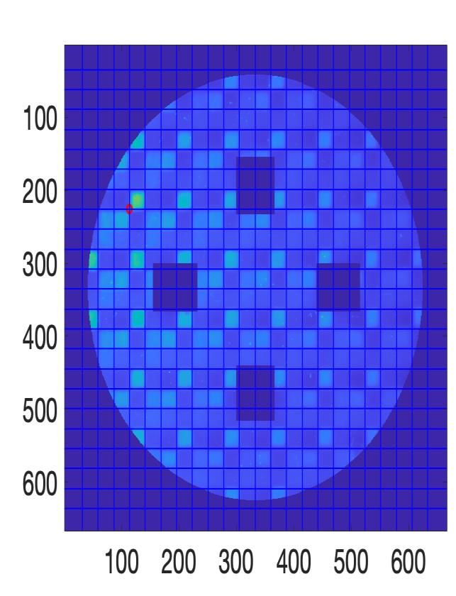
High-rep-rated PROBIES setup enables rapid analysis

PROBIES Mask Raw data Grid registration Pixel
 Y/pixel

 X/pixel X/pixel

 52
Spectral dispersion appears to be a strong tuning knob
on proton dose

 Laser spectral phase: (ω) = 0 + 1(ω - ω0) + 2(ω - ω0)2/2 + 3(ω - ω0)3/6 + ...
 -GDD ( 20)

 TOD=0

 TOD0

+GDD ( 2>0)

 The highest dose was obtained when the third order
 dispersion was positive, creating a post-pulse.

 53
Our results show promising dispersion tuning effects,
especially with third order dispersion

 Proton Dose
 ▪ 48 spectral phase shaping shots
 were taken on one day at CSU.

 ▪ On the left, the results from the 7J
 scan are plotted for proton energies
 from 3.9 to 7.3 MeV.

 ▪ Third order spectral phase improved
 proton dose when the second order
 spectral phase was close to zero.

 ▪ This pattern persisted up through
 7.3MeV, when proton dose dropped
 off.

 54
Future work involves recently completed beam time to
 further explore this relationship between spectral phase
 and proton dose.

▪ Second LaserNet experiment time
 recently completed (Dec 2022) to
 further explore this work and expand
 laser parameter scan

▪ Ensemble simulations for
 interpretation of results

▪ Comparison to other diagnostics and
 calibration of PROBIES diagnostic

▪ PROBIES analysis can be used in
 feedback loop and to enable transfer
 learning

 55
And finally, I will bring all of these capabilities together
for a new experiment.

 λ
High-intensity, on-
shot laser electric
field measurement

Temporal
structuring for
optimization of
laser-driven particle
sources

Spatiotemporal
structuring of laser
intensity and phase
to generate optical
vortices

 Simulation by E. Grace

 56
Optical vortices may benefit TNSA by providing a
tailored electron sheath for ion acceleration.

 57
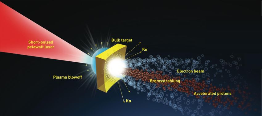
Ion acceleration processes such as TNSA can benefit
from advances in laser technology.

TNSA with a Gaussian Pulse TNSA with a Donut Laser Pulse

 E E?

 Target Target
 Hot Hot
 Ablated electron Ablated electron
 plasma sheath plasma sheath

 How can we use structured light to tailor our particle acceleration?

 58
Preliminary simulations compare proton distribution
 over time for Gaussian and donut modes

 t = 0.3ps t = 0.6ps t = 1.2ps t = 2ps
 200
Gaussian Mode

 150
 r (μm)

 100

 50

 0
 -50 0 50 100 150 200 -50 0 50 100 150 200 -50 0 50 100 150 200 -50 0 50 100 150 200
 z (μm) z (μm) z (μm) z (μm)
 t = 0.3ps t = 0.6ps t = 1.2ps t = 2ps
 200
Donut Mode

 150
 r (μm)

 100

 50

 0
 -50 0 50 100 150 200 -50 0 50 100 150 200 -50 0 50 100 150 200 -50 0 50 100 150 200
 z (μm) z (μm) z (μm) z (μm)
 *Simulations by J. Kim

 59
How can we create high-intensity optical vortices?

 Simulated Measured
 Intensity + Phase = Wavefront Intensity Intensity

 m=0
m=0
m=1

 m=1
m=2

 A. Longman et al, Opt. Lett. (2020).

 Off-axis spiral phase mirrors, which we are making now in
 collaboration with the MRF at Livermore, show promise for
 generating high-intensity optical vortices but must be validated.
 60
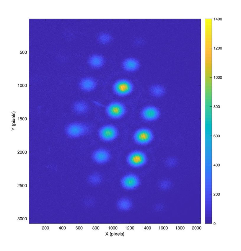
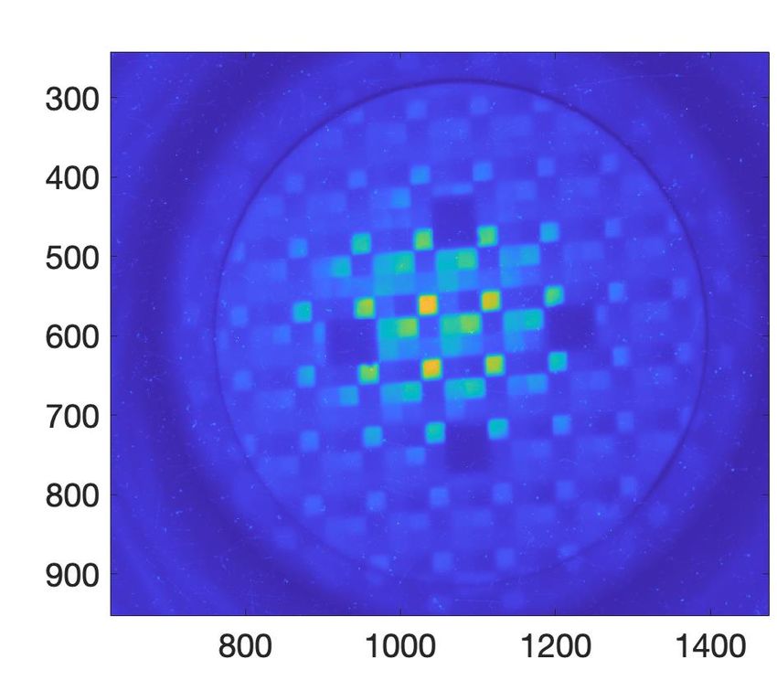
Current validation methods have been limited to spatial
and temporal measurements taken separately.

Currently, validation of the high- However, the defining feature of an optical
intensity optical vortex has been vortex is the spiral spatial phase, which would
limited to space and time be measured on-shot with STRIPED FISH.
measurements taken separately.
 A.U.
 1

 200

 400

 y/pix
 600
 0.5
 800

 1000

 1200
 0
 200 400 600 800 1000 1200
 x/pix

 STRIPED FISH provides the first high-intensity measurement
 61
 of the spatiotemporal phase that defines optical vortices.
However, without spatiotemporal validation, we will not
know whether we are generating a simple optical vortex

 λ

 62
…or a spatiotemporally perturbed beam with no
characteristic ring shape at the focus.

 λ

 63
This work is ongoing with a recent LaserNet proposal
awarded for BELLA.

▪ STRIPED FISH has been built at BELLA
 and is in place retrieving the Raw STRIPED FISH trace at BELLA
 spatiotemporal distortions on-shot.

▪ The experiment is scheduled for May
 2023 and funded for $25k (PI: E. Grace,
 K150)

 65
In summary, this talk discussed laser metrology for
precision-controlled secondary sources.

 On-shot measurement
High-intensity, on-
 of COMET wavefront
shot laser electric
field measurement Application to NIF-ARC

Temporal
structuring for Recent work found
optimization of that laser dispersion
laser-driven particle tuning is a strong knob
sources on proton acceleration.

Spatiotemporal
structuring of laser Current work
intensity and phase investigates the use of
to generate optical optical vortices for
vortices TNSA.

 66
You can also read