Novel application of multitubular nozzle in throughfeed centerless grinding process of bearing steel - SAE 52100
←
→
Page content transcription
If your browser does not render page correctly, please read the page content below
Novel application of multitubular nozzle in through-
feed centerless grinding process of bearing steel
SAE 52100
Luiz Maurício Gonçalves Neto
Schaeffler Technologies AG & Co. Herzogenaurach
Rafael Lemes Rodriguez
São Paulo State University
José Claudio Lopes
São Paulo State University
Fernando Sabino Fonteque Ribeiro
São Paulo State University
Grzegorz M. Królczyk
Opole University of Technology
Luiz Eduardo de Ângelo Sanchez
São Paulo State University
Hamilton José de Mello
São Paulo State University
Eduardo Carlos Bianchi ( eduardo.bianchi@unesp.br )
UNESP https://orcid.org/0000-0003-2675-4276
Research Article
Keywords: through-feed centerless grinding, cutting fluid, multitubular nozzle, compressed air
Posted Date: August 5th, 2021
DOI: https://doi.org/10.21203/rs.3.rs-759258/v1
License: This work is licensed under a Creative Commons Attribution 4.0 International License.
Read Full License
Page 1/25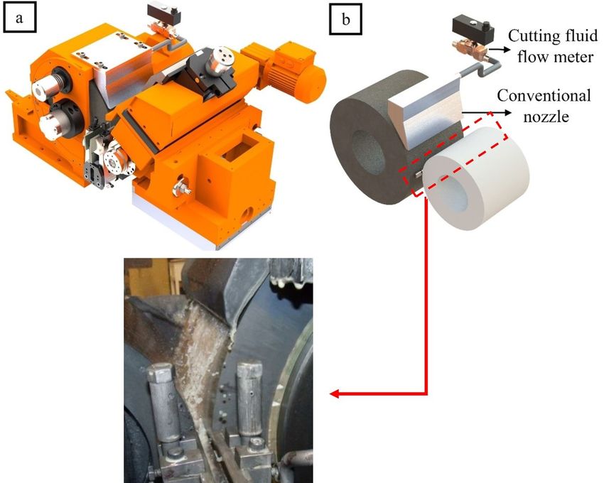
Abstract
Through-feed centerless grinding is a high-productivity machining process widely used for mass
production of cylindrical parts and rotationally symmetrical parts in automotive and bearing industries.
Grinding process is strictly related to large amount of heat generated in the cutting zone. This process
characteristic makes pivotal and indispensable the effects of lubrication and cooling provided by metal
working fluid (MWF). In this regard, this work aims to contribute to the study of MWF application in
grinding process, analyzing the effects of the optimized technique developed for an eco-friendlier use of
MWF by the application of a novel multitubular nozzle. The results obtained for the novel designed
multitubular nozzle with compressed air outperformed the conventional nozzle system with lower oil
volume employed.

1 Introduction
According to Gallego [1], the through-feed centerless grinding is a high-productivity machining process,
employed to manufacture parts with tight diametric tolerances in serial production as reported by Krajnik
et al [2]. Shih [3] infers that this process is widely used for mass production of cylindrical parts and
rotationally symmetrical parts in automotive and bearing industries as stated by Krajnik et al. [4].
Regarding to other grinding processes, Meyer and Krajnik et al. [5] explain that it is considered complex
due to a variability of cutting parameters. Schmidt [6] describes that its versatility allows machining
several types of materials, including several alloy steels, the most common types of ferrous metals, as
well as several non-metallic materials such as ceramics, cork, glass, plastics, porcelain, rubber and wood.
In order to reach the required accuracy with high productivity in centerless through-feed grinding, the
setup of proper conditions is indispensable as presented by Otaghvar et al.[7].

Marinescu [8] explains that when the grinding process is compared to other finishing machining
processes, such as lapping and polishing processes, the major disadvantage related to this process is the
excessive heat generated in the cutting zone, i.e., the interface between the workpiece and the abrasive
tool. According to Malkin and Guo [9] and Bianchi et al. [10] whether the temperature in the grinding zone
during process is excessive, thermal damage can occur on the ground part, such as: tensile residual
stress, microstructural changes, increase or decrease in microhardness on ground surface and the
occurrence of cracks. According to Malkin and Guo [11], the expansion or contraction of the part, caused
by the thermomechanical effects during the grinding process, contribute to problems with the precision
and distortions of the final part. Brinksmeier et al. [12] infer that the combined effect of lubrication and
cooling of metal working fluid (MWF) is an indispensable resource to avoid thermal damage to the part
during grinding. In addition, Irani et al. [13] state that thermal damages are one of the main factors that
restrain the grinding process efficiency.

From an ecological point of view, most MWFs currently employed are harmful to the environment. In
addition to environmental problems, Tawakoli et al. [14] state that the disposal and maintenance of these
fluids result in high costs to industries due to the fact that these activities must be carried out by

                                                  Page 2/25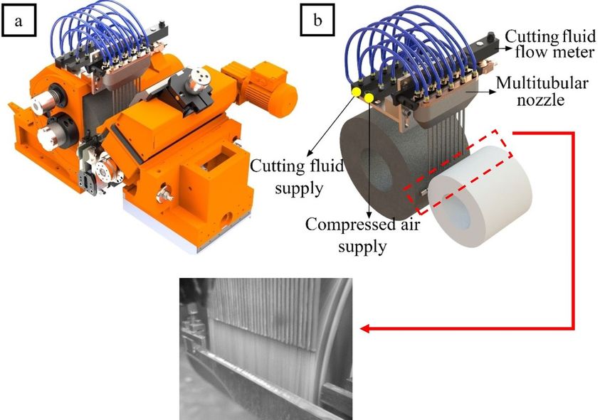
specialized professionals and require the analysis and approval of competent environmental
organization as reported by Babic et al. [15]. In this context, there is a worldwide trend to reduce or
mitigate the usage of compounds that cause risk to the environment and human health and,
simultaneously, there is an incessant search performed by companies and global researchers in order to
reduce energy consumption and manufacturing costs. Today, MWFs in abundance (flood application) are
widely used in industries, mainly in centerless grinding processes due to the high material removal rates
(MRRs), the size of the cutting wheels, the condition of MWF application and the type of the lubri-cooling
nozzle, considering that the conventional nozzle is still the most commonly used in this process.
According to Klocke [16], the performance of grinding process depends on the size of the grinding wheel,
width of spark out zone, pivoting angle of grinding wheel, workpiece dimensions, MRR, type of nozzle,
peripheral speed and pressure of the MWF, the flow rate of lubri-cooling fluid in the centerless grinding
can reach high values, i.e., 400 L / min. Webster [17] infers that the flow rate can be defined according to
the power consumed during the grinding process, because higher MRR requires more volume of MWF.
According to Webster [17], a flow rate of 7.57 ((L / min) / hp) is an amount of fluid suitable for grinding
processes for conventional nozzles.

In the economic point of view, there is a search for new lubrication strategies in industrial machining
processes. About 8–16% of the total machining costs are related to the use of cutting fluids and in many
cases are higher than the costs with cutting tools as reported by Tawakoli et al. [18]. According to
Sanchez et al. [19], the costs with lubrication cooling are significantly higher than the costs with tools.
Lubri-cooling costs represent 18% in relation to machining costs, 40% is related to equipment for cooling
and filtering MWF and 22% for the disposal of waste generated by the grinding process. The cost of fluid
supply in lubri-cooling central represents around 14%, 7% is spent on energy and 10% is spent on fluid
analysis and control.

In order to reduce manufacturing costs and meet environmental requirements, several lubri-cooling
techniques are currently being developed, such as minimum quantity lubrication (MQL), optimized
application, among others. According to Sreejith and Ngoi [20], dry machining is an ecologically desirable
method, being considered necessary for companies, including as a way of complying with environmental
laws. This technique has several advantages, as it does not pollute the atmosphere or water, there is no
fluid residue in the chips, which reduces the cost of disposal and is not harmful to human health.
According to Sen et al. [21], the manufacturing industries are continuously searching for lubri-cooling
techniques which minimize the utilization of MWFs throughout the metal cutting process due to financial
and ecological anxieties. The authors infer that the general preposition of the standards in the ISO 14000
is to shield environmental instability through socioeconomic prerequisites.

Despite its ecological advantages, Tawakoli at. al. [22] state that dry grinding still presents important
limitations to be applied in industrial process due to its economic inefficiency caused mainly by the
rejection rates of parts with thermal damage. Khanna et al. [23] evaluated the performance of dry, wet,
MQL, and cryogenic machining of 15 − 5 Precipitation Hardened Stainless Steel (PHSS) and observed
that the 6.27 % higher value of energy consumption in dry machining as compared to other lubri-cooling
                                                   Page 3/25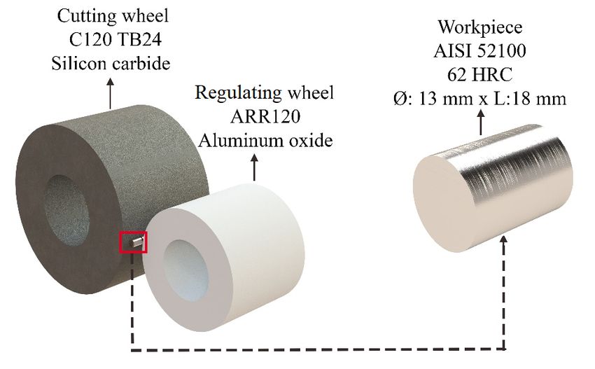
methods. According to Maruda et al. [24], dry machining is not recommended for surfaces with high
accuracy requirement, because higher amount of heat is transferred to the workpiece as a result of the
friction between tool/chip interface, affecting negatively the tool life. In grinding, the total elimination of
MWF results in higher temperatures during the grinding process, which may affect the surface integrity
and geometric precision of the ground part, in addition to an increase in wheel wear and clogging
phenomenon as reported by Oliveira et al [25]. This technique is generally applied to processes with
defined cutting geometry, such as turning and milling.

A promising approach to overcome the limitations of dry machining is through the MQL technique. This
technology combines the functionality of refrigeration with very low fluid consumption, with flow rates
ranging from 10 mL/h to 100 mL/h and application pressures ranging from 0.39 MPa to 0.59 MPa,
eliminating the need for disposal and minimizing possible impacts to the environment as inferred by
Klocke et al. [26], since all the fluid amount is consumed directly during process. However, this technique
still needs to be improved in order to be used in grinding processes, especially in centerless grinding
processes using conventional grinding wheels. For high rates of MRR, the flow rate of lubricant is
inefficient to remove the chip from the cutting zone, resulting in wheel clogging. Thus, the chip lodged in
wheel pores reduces the grinding wheel active surface (GWAS) and increases load on tool, decreasing the
lubrication capacity of the cutting zone, hindering the surface final quality and greater diametric wheel
wear. According to Rodriguez et al. [27], the MQL technique with water addition and wheel cleaning jet
indicates an environmental-friendly potentiality to reduce risks to environment and carbon footprint. On
the other hand, Lopes et al. [28] infer higher cutting temperature are generated in pure MQL grinding, and
consequently accentuating the clogging occurrence on GWAS.

De Moraes et al. [29] studied application of the MQL with water for AISI 52100 steel grinding and reported
that this lubri-cooling technique reduced surface roughness, form deviation error and wheel wear due to
its higher cooling capacity, presenting results close to conventional MWF application (flood). On the other
hand, the authors infer that the addition of water in MQL grinding decreases the lubrication effect in
cutting zone, consequently increasing the cutting power. However, the addition of water in MQL grinding
shows to be a viable alternative to improve the wider employability of this lubri-cooling technique. Garcia
et al. [30] tested the addition of 1:5 oil-water ratio in the MQL grinding with wheel cleaning jet of AISI
52100 and concluded that this technique outperformed the other dilution proportions (1:0, 1:1 and 1:3)
and produced surface finishing quality results 22% higher than the flood technique.

Studies carried out by Tawakoli et al. [14], Webster and Grün [17] and Monici et al. [31], indicate that the
optimized application and new nozzle designs can be the most efficient means to make the application
more efficient possible, allowing the reduction of the consumption of MWFs in the grinding processes.

Aiming to guarantee a better quality of the ground parts and the reduction of manufacturing costs and
risks to human health related to the use of MWFs during the through-feed centerless grinding process,
this current work propose the development of an optimized method of lubri-cooling in order to make it
possible a more environmentally friendly application of MWFs, thus guaranteeing the integrity of the

                                                    Page 4/25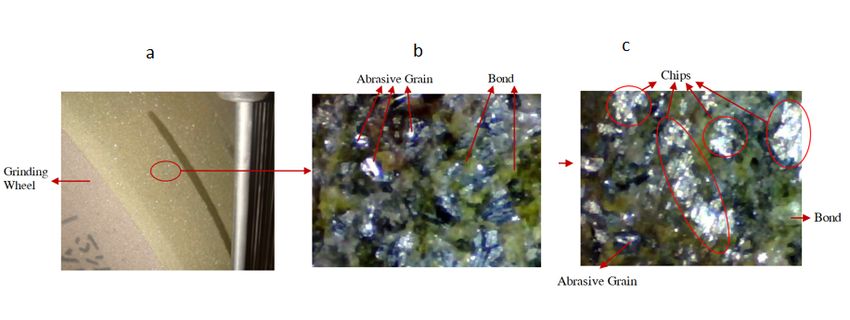
ground surface part, while reducing manufacturing costs and lowering environmental impacts. In a
groundbreaking way, this study compared the effects caused on ground samples by the conventional
application of cutting fluid and the optimized lubri-cooling method that employed a new design of
multitubular nozzle with fluid emulsion and emulsion with compressed air simultaneously.

2 Experimental Procedure
Tests were carried out on a centerless grinder, manufactured by Herminghausen, model SR4-25. A silicon
carbide grinding wheel (model C120 TB24, outer diameter of 500 mm and 250 mm of width) was used in
tests. The Al2O3 regulating wheel with rubber bond (model ARR120, outer diameter of 300 mm and 250
mm of width). Both wheels were supplied by SIVAT abrasives. For the specimens, geometries were
selected with 13 mm in diameter and 18 mm in length, consisting of SAE 52100 steel (quenched and
tempered), with an average hardness of 62 HRC and used for rollers bearings. Details related to wheels
and specimens are shown in Fig. 1. In order to guarantee an ideal condition for the evaluation of the
specimens, the wheels were dressed after each test.

The cutting wheel was dressed with a conglomerate dresser (10 mm wide, 4 mm heigh and 10 mm thick),
while for the regulating wheel a single point dresser was applied. The processes were done according to
the manufacturer's recommendations, due to the nature of each wheel.

This study evaluated different lubri-cooling techniques: conventional (CN), multitubular with emulsion
(ME) and multitubular with emulsion and compressed air (ME + CA). The emulsion cutting fluid was
employed at 4 different flow rates using conventional nozzle and multitubular nozzle. For all tests, the
cutting fluid used was Syntilo 290 BR, supplied by Castrol, 4% of oil concentration.

The conventional application system is shown in Fig. 2 (a) Fig. 2 (b) shows the position of the
conventional nozzle in front of the wheels and the workpiece. The conventional nozzle delivers the fluid
abundantly, with great dispersion and with a non-uniform profile in the lubrication area. The flow rates for
conventional application were 10; 20; 30 and 40 L / min with a pressure of 0.5 MPa.

The system is comprised of the multitubular nozzle, machine tool, grinding wheels and workpiece is
shown in Fig. 3a. The nozzle geometry was based on the one proposed by Webster [17], indicating that
application of this nozzle generates a reduction in the cutting fluid turbulence at the nozzle outlet,
providing a jet of directional fluid with low dispersion. In order to produce a good fluid delivery, the nozzle
was positioned at a distance of 80 mm from the cutting region. The positioning of the nozzle at the
cutting interface is shown in Fig. 3b. The flow rate of compressed air during the tests using the
multitubular nozzle was 170 L / min, with a pressure of 0.6 MPa, generating a fluid speed of 45 m / s
(similar to the peripheral speed of the wheel, i.e., cutting speed).

Table 1 shows the process parameters and the lubri-cooling methods employed in the tests.

                                                    Page 5/25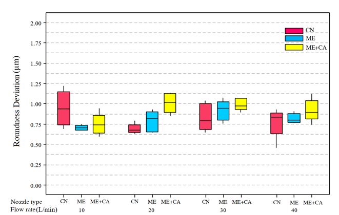
Table 1
                          Process parameters and lubri-cooling methods.
Process          Through-feed centerless grinding process

Grinder          Herminghausen model SR4-25

Grinding Wheel   Cutting wheel                                    Regulating wheel

                 C120 TB24 – Silicon carbide                      ARR120 – Aluminum oxide

                 Sivat Abrasives                                  Sivat Abrasives

Cutting Speed    45 m/s
(Vs)

Through Feed     2.5 m/min

Stock material   0.1 mm
removed

Cutting Wheel    1750 rpm
Rotation

Regulating       200 rpm
Wheel Rotation

Workpiece        AISI 52100 (62 HRC)

Dresser          Diamond conglomerate − 10 mm×4                   Single edge dresser (Al2O3 Drag
                 mm×10 mm (SiC cutting wheel)                     wheel)

Depth of         3 µm (SiC Cutting Wheel)                         3 µm (Al2O3 Regulating Wheel)
dressing

Dressing speed   500 mm/min

Dressing steps   5

Fluid            Conventional nozzle             Multitubular nozzle       Multitubular nozzle with
application                                      (MN)                      compressed air
                 (CN)
                                                                           (MN + CA)

Cutting Fluid    Syntilo 290 BR by Castrol       Syntilo 290 BR by         Syntilo 290 BR by Castrol
                                                 Castrol

MWF dilution     Emulsion − 4%                   Emulsion − 4%             Emulsion − 4%

Cutting Fluid    0.5 MPa                         0.5 MPa                   0.5 MPa
Pressure

Cutting Fluid    10; 20; 30; 40 L/min            10; 20; 30; 40 L/min      10; 20; 30; 40 L/min
Flow Rate

Compressed Air   Not applicable                  Not applicable            0.6 MPa
Pressure

                                             Page 6/25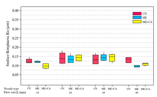
Process              Through-feed centerless grinding process

 Compressed Air       Not applicable                   Not applicable            170 L/min
 Flow Rate
In order to check and compare all the grinding conditions produced, surface roughness, roundness
deviation and residual stress were analyzed. The integrity of the ground surface was also checked by
magnetic particles inspection and superficial burning was detected by the chemical attack method and
micrograph. For the GWAS (grinding wheel active surface), the topography of the cutting surface was
evaluated.

The mean surface roughness (Ra) was measured the rougher equipment model Perthometer M2,
manufactured by Mahr Ltda. A 0.8 mm cut-off value was applied, using a Gaussian filter for roughness
measurements. The measurements of the roundness deviations were performed using an equipment
model MWA 100 B, manufactured by SKF. All results shown are averages of 5 measurements performed.

One of the parameters that can indicate the effectiveness of the grinding process is the residual stress.
Due to the heat generated by the friction in the cutting zone, along with the mechanical deformations
resulting from the chip removal process, the ground surfaces show surface changes, whether they be
tensile or compression as reported by Macherauch [32]. According to Field et al.[33], excessive tensile in
these components can compromise the mechanical reliability of the part. The Barkhausen Noise method
was employed to measure the residual voltage, performed by a Rollscan 300 CPU s / n 1775 device,
adjusted with a magnetization frequency of 200 Hz, with a magnetization voltage of 15 V, together with a
70–200 kHz and an S6362 sensor. The pieces were fixed on a bracket that allowed them to rotate when
measuring their axial direction. The data were collected using ViewScan software.

Finally, the GWAS was observed after performing each test by a portable digital microscope under
magnification of 50X. This process observation aimed to investigate GWAS condition in terms of
clogging occurrence.

3. Results And Discussions
This section discusses the results obtained for the different MWFs application proposed (CN, ME and ME
+ CA) in through-feed centerless grinding process of bearing steel SAE 52100.

3.1. Analysis of surface roughness and GWAS condition
The Fig. 4 presents the mean surface roughness (Ra) values for different lubri-cooling techniques (CN –
conventional nozzle, ME – multitubular with emulsion and ME + CA – multitubular with emulsion and
compressed air) and different flow rates employed.

By Fig. 4 and irrespective of nozzle used, it can be seen that the reduction of surface roughness values is
related to the increase of flow rate. As reported by Ramesh et al. [34] and Bianchi [10], a higher flow rate

                                                  Page 7/25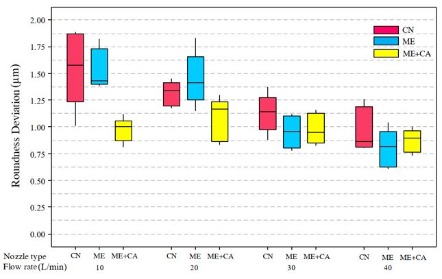
results in higher coolant velocity, improving the lubrication effect and contributing to a better grinding
heat dissipation characteristic. In general, the results obtained for ME and ME + CA nozzles were lower
than those obtained for CN.

Regarding to application of ME + CA technique, it was noticed that this technique resulted in lower values
of surface roughness and variability in comparison to ME and CN. For tests with ME + CA nozzles at the
flow rate of 10 L/min, the surface roughness obtained was 73 and 28% lower than, respectively, CN and
ME nozzles.

For tests with ME + CA nozzles at the flow rate of 20 L/min, the surface roughness obtained was 24 and
18% lower than, respectively, CN and ME nozzles. For tests with ME + CA nozzles at the flow rate of 30
L/min, the surface roughness obtained was 30% lower than CN nozzle and no mathematical difference in
comparison to ME nozzle. For tests with ME + CA nozzles at the flow rate of 40 L/min, the surface
roughness obtained was 17 and 9% lower than, respectively, CN and ME nozzles.

The lowest surface roughness values obtained for ME + CA can be justified by the fact that compressed
air increases the velocity of cutting fluid in the nozzle end, producing a higher force in the cutting zone.
Higher is the force of fluid jet, higher is the pressure of cutting fluid in the cutting zone; promoting a better
cleaning of chips generated in the cutting zone during the grinding process and consequently increasing
the lubricant effect of lubri-cooling method. According to Bianchi et al [10], the use of wheel cleaning jet
in MQL with different flow rates (30, 60 and 120 mL/h) significantly lowered the surface roughness Ra for
AISI 4340 steel grinding process, producing results similar to flood MWF method.

The best surface roughness values were obtained for the highest flow rates of the cutting fluid, that is, 30
L / min and 40 L / min using the ME + CA nozzle, thus confirming a better grinding condition. Unlike the
CN, the ME + CA nozzle promotes a directional jet, with low dispersion at the nozzle outlet and with a
speed close to the peripheral speed of the grinding wheel, due to the use of compressed air as an
auxiliary fluid. With this nozzle, the fluid penetrates easily in the aerodynamic barrier around the wheel
and guarantees a greater amount of fluid in the cutting zone, thus ensuring a better lubricating and
cooling effect. The greater dilution of the cutting fluid provides a faster removal of the chips, preventing
them from affecting the quality of the piece. Bianchi et al. [10] state that the occurrence of clogging
phenomenon on GWAS is hindered by pure oil application because of higher fluid viscosity results in solid
suspension, and consequently grout formation which lodges in the wheel pores.

Yoshimura et al. [35] infers that the addition of water in MQL grinding generates lower plastic
deformation caused by higher coolant effect by water addition, i.e., higher heat dissipation in the cutting
zone by phase transition (from liquid water to vapor). According to Sato et al. [36], this reduces the wheel
clogging phenomenon and keeps the wheel grit sharp [37].

According to Ramesh [34], the increase of fluid speed promotes a lubricating effect with better heat
dissipation effect in the grinding and, thus, lower surface roughness values. According to Daniel et al.
[38], the MWF heat transfer increases with the fluid flow velocity. The Turkey method was employed in
                                                    Page 8/25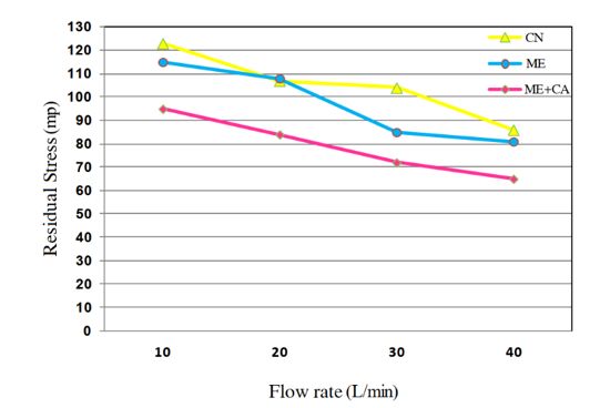
order to compare the surface roughness values for ME + CA technique in different flow rate, considering a
significance level of 5%. Regarding to flow rate values, the differences in surface roughness were small
and were significant between 40 L / min − 10 L / min and 40 L / min − 20 L / min, as shown in Fig. 5.
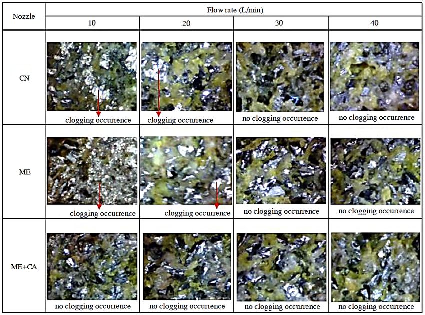
The high values of surface roughness Ra for the tests using the CN and ME application, for flow rates of
10 and 20 L / min, as shown in Fig. 4, are related to the low efficiency in heat dissipation and in removing
the chip from the cutting zone, which may cause the clogging phenomenon on GWAS. Figures 6 (a) and 6
(b) depict evidence of the occurrence of this phenomenon. For the other conditions, no wheel clogging
was observed. According to Malkin [39], the presence of chips in the cutting region hinders the cutting
performance, increases efforts during material removal and, consequently, increases the surface
roughness value. According to Walker et al. [40], the eco-efficient application of a cleaning jet by
compressed air diminishes the clogging phenomenon, further decreasing the volume of grout formation
on GWAS and, consequently, minimizing the effects of the rubbing and ploughing effects on the ground
surface. Thus, Rodriguez et al. [41] state that the surface roughness results can be reduced by 45%.
Additionally, the authors infer that excessive temperatures in the contact zone result in reduction of yield
strength and increasing of material strain from the ground material, increasing the lodging and adherence
of chips in the grinding wheel pores.
Comparing the surface conditions of the grinding wheel using the CN (Fig. 6a) and those obtained for ME
(Fig. 6b) at 10 L / min, it is possible to observe in both cases a probable clogging of the GWAS. For the
condition employed in the current tests, the surface roughness values generated for CN and ME
application did not show mathematically significant differences.
The ME + CA application presented a more efficient condition than the other two lubri-cooling methods,
resulting in lower surface roughness values. This can be explained by the high outlet speed of the cutting
fluid jet using this technique. According to Webster and Grün [17], the fluid outlet speed associated with
the flow rate and the type of nozzle have a significant influence on the coolant effect, as it increases the
cleaning efficiency in cutting zone. Moreover, it facilitates the removal of material and results in better
surface quality. Thus, the process performance was improved by the application of the cutting fluid
associated with the high speed provided by the auxiliary fluid using ME + CA technique and, thus, greater
pressure force in the cutting zone. For all conditions tested for ME + CA, no evidence of clogging on
GWAS was observed. Figure 6 (c) shows the condition of GWAS for the lowest flow, i.e., 10 L / min.
Figure 6. Wheel topography for (a) CN, (b) ME and (c) ME+CA at 10 L/min.
As can be seen in Fig. 6, higher wheel wear could be seen for ME application. According to Rodriguez et
al. [41], the abrasive tool wear occurs by the following mechanisms: grain detachment from bond, grain
fracture and wear. As reported by Martini et al. [42], excessive temperatures promote the reduction of
bond material strength, what increases tool wear. As observed for ME + CA application, the cutting force is
distributed on a larger area of grain protrusion (larger GWAS), what results in higher MRR and tool wear
minimization [43].
Page 9/25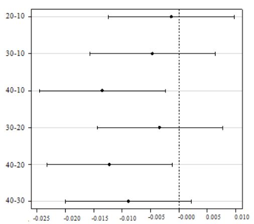
Figure 7 shows the topography of GWAS for all conditions tested. By the analysis of this figure, it can be
observed clogging on GWAS for CN and ME at flow rates of 10 L / min and 20 L / min.

Figure 8 shows the Ra surface roughness recorded, for depth of cut of 0.03 mm and different values of
flow rate.

In general, it can be seen in Fig. 8 that the Ra surface roughness values for all conditions tested were less
than the maximum tolerance specified for the grinding process of cylindrical rollers for SAE 52100 steel
bearings, i.e., 0.15 µm. According to Malkin and Guo [44], the allowable range of Ra roughness values for
the grinding process is between 0.2 to 1.6 µm. Thus, all values obtained using the CN method and the
optimized methods (ME and ME + CA) are within the tolerance range for the grinding process.

Analyzing Fig. 8, it can be observed that lower values of surface roughness at 40 L / min when the ME +
CA method is employed are related to the higher speeds of the cutting fluid and the directional output of
the cutting fluid promoted by multitubular nozzle. Despite presenting lower values of surface roughness
when compared to ME at 40 L / min, the multiple comparison test, as shown in Fig. 9, does not present
mathematically significant differences between both techniques at 40 L / min. The higher speeds of the
fluid at the outlet of the nozzle promote the reduction of friction, due to greater presence of lubricant in
the cutting region.

3.2. Roundness Deviation
The values of the roundness deviation obtained for the tested lubricooling conditions and material
removal of 0.10 mm are shown in Fig. 10. Comparing the results of the roundness from Fig. 10, it is
observed that the increase in flow rate resulted in lower roundness deviation, in particular, conditions
tested with the CN and ME. In general, the values of the roundness deviation for ME + CA application were
lower in comparison to CN application.

The reduction of roundness deviation is due to the fact that the higher flow rate promotes a better cooling
effect in the cutting zone. According to Demeter and Hockenberger [45] and Malkin [39], greater is the
difficulty of the fluid penetration in the cutting zone, greater is the amount of heat distributed to workpiece
and consequently producing thermal expansion and causing an increase in the form deviation, i.e.,
mainly amplifying the roundness deviation. The best result of the roundness deviation can be seen in
Fig. 10 for ME and ME + CA technique at 40 L / min.

The results of the mean values and variability of the roundness deviations (for total removal of 0.03 mm)
are shown in Fig. 11.

By Fig. 11, it can be seen that higher values of the roundness deviations were recorded for the tests ME +
CA at 20, 30 and 40 L / min. For the flow rate of 10 L / min, the value of the roundness deviation was
lower in relation to the tests with CN and ME application.

                                                  Page 10/25
For all tested conditions, the mean values of the roundness deviations were kept below the maximum
allowed tolerance (1µm) for the ground rolling rollers. The roundness deviation during the centerless
grinding process is mainly influenced by the geometric variables (inclination angle of regulating wheel,
rest blade) and dynamics of the grinding process (natural frequency of machine, wheel rotation, among
others). In addition, it is influenced by the magnitude of wheel wear, the MRR (material removal rate) and
specific energy.
In addition, the roundness profile of the machined samples was evaluated and concluded that the
deviation was not influenced by the dynamic variables of grinding process. The roundness deviations for
all conditions tested did not show deviations in the form of periodic undulation, therefore, not due to the
influence of dynamic factors in grinding process.
3.3. Residual Stress
The results of the residual stress measurements in “mp” (elastic magnetic parameter) using the
Barkhausen noise method for all tests with CN, ME and ME + CA techniques with material removal of 0.03
mm, as shown in Fig. 20.
The mean values of the residual stress results for the lubri-cooling conditions with CN, ME and ME + CA,
as shown in Fig. 12.
Barkhausen residual stress analysis is a non-destructive quantitative control method. Workpieces with
high values of residual compressive stresses indicate low Barkhausen noise intensity (mp). In order to
define the limits between the residual compressive and tensile stresses, an investigation of the ground
surface using the X-ray diffraction technique was performed. Through the stress values (MPa) by the X-
ray diffraction and Barkhausen noise (mp) technique it is possible to define a factor to convert the values
in “mp” to “MPa”.
As shown in Fig. 20, it can be seen that the lubri-cooling method using the ME + CA presented, in general,
residual stresses lower than those generated through the methods using the CN and ME + CA techniques.
Thus, it can be observed that workpieces ground with ME + CA technique suffered fewer thermal effects.
Comparing the residual stress values (Fig. 12) with the results of the metallographic analysis, a
maximum residual stress value can be admitted for the rectification of SAE 52100 steel of 80 mp, due the
fact that the conditions using the ME with a flow rate of 40 L / min and for the ME + CA with a flow rate of
30 and 40 L / min, did not produce changes in the microstructure, i.e., the ground workpieces without
grinding burns.
4 Conclusion
Based on the results and discussions previously presented, the following sentences can be concluded:
Page 11/251. In general, the conditions obtained for the ME and ME+CA application proved to be more efficient than
those obtained of CN application regarding to all parameters analyzed, i.e., surface roughness and
integrity, roundness deviation and thermal damage.
2. Regarding to surface roughness results, it was noticed that the application of ME+CA technique
resulted in lower values of surface roughness and variability in comparison to ME and CN. For tests with
ME+CA nozzles at the flow rate of 10 L/min and depth of cut of 0.1 mm, the surface roughness obtained
was 73 and 28% lower than, respectively, CN and ME nozzles. For tests with ME+CA nozzles at the flow
rate of 20 L/min, the surface roughness obtained was 24 and 18% lower than, respectively, CN and ME
nozzles. For tests with ME+CA nozzles at the flow rate of 30 L/min, the surface roughness obtained was
30% lower than CN nozzle and no mathematical difference in comparison to ME nozzle. For tests with
ME+CA nozzles at the flow rate of 40 L/min, the surface roughness obtained was 17 and 9% lower than,
respectively, CN and ME nozzles.
3. Both flow rate and the type of nozzle significantly influence the values of surface roughness,
roundness deviation, residual stress and depth of the thermally affected layer during the grinding
process.
4. Comparing the results of the roundness for depth of cut of 0.10 mm, it is observed that the increase in
flow rate resulted in lower roundness deviation, in particular, conditions tested with the CN and ME. In
general, the values of the roundness deviation for ME+CA application were lower in comparison to CN
application. For the application of ME+CA technique, the mean values of the roundness deviations
obtained, in all conditions tested, were below the maximum allowable tolerance for through-feed
centerless grinding process of rolling rollers, that is, 1 μm.
5. The surface roughness values for the tests using the ME+CA were satisfactory for all conditions
tested, with an average roughness value (Ra) below 0.15µm. The application of compressed air proved to
be an efficient way to improve the cooling condition during the grinding process, since during the tests
under ME+CA technique, no clogging occurrence on GWAS was recorded.
6. The analysis of results indicates that the new nozzle concept developed using either ME or ME+CA
technique proved to be a viable alternative to optimize the grinding conditions and to replace the
conventional nozzle commonly used in through-feed centerless grinding process. By the results obtained
in this work, it can inferred that the use of the new nozzle concept is a viable way to reduce the MWF
consumption during the centerless grinding process, guaranteeing the integrity of the ground part.
Declarations
ETHICAL APROVAL
The authors declare that this manuscript was not submitted to more than one journal for simultaneous
consideration. Also, the submitted work is original and not have been published elsewhere in any form or
Page 12/25language
CONSENT TO PARTICIPATE AND PUBLISH
The authors declare that they participated in this paper willingly and the authors declare to consent to the
publication of this paper.
AUTHORS CONTRIBUTIONS
Luiz Maurício Gonçalves Neto Writing Original Draft; Writing Review & Editing; Visualization;
Conceptualization; Formal Analysis; Investigation; Validation.
Rafael Lemes Rodriguez Writing Original Draft; Writing Review & Editing; Visualization; Conceptualization;
Formal Analysis; Investigation; Validation.
José Claudio Lopes Writing Original Draft; Resources; Conceptualization; Methodology; Project
administration
Fernando Sabino Fonteque Ribeiro Writing Original Draft; Writing Review & Editing; Visualization;
Conceptualization.
Grzegorz M. Królczyk Writing - Review & Editing; Conceptualization; Supervision.
Luiz Eduardo de Angelo Sanchez Writing - Review & Editing; Conceptualization; Supervision.
Hamilton José de Mello Conceptualization; Methodology; Formal Analysis; Investigation; Validation.
Eduardo Carlos Bianchi Funding acquisition; Conceptualization; Resources; Supervision; Project
administration.
FUNDING
Authors are thankful to São Paulo Research Foundation (FAPESP), CAPES (Coordination for the
Improvement of Higher Level Education Personnel).
ACKNOWLEDGEMENTS
The authors also are thankful to Schaeffler Technologies AG & Co by the support to this work..
COMPETING INTERESTS
The authors declare that there is no conflict of interest regarding the publication of this paper.
References
Page 13/251. Gallego I (2007) Intelligent Centerless Grinding: Increasing Precision and Productivity. Center for
Materials Processing and Tribology Seminar
2. Krajnik P, Drazumeric R, Vrabic R, Kopac J (2009) Advances in Centerless Grinding Modelling and
Simulation. Advances in Production Engineering Management 3:115–126, ISSN 1854–6250
3. Shih AJA New Regulating Wheel Truing Method for Through-Feed Centerless Grinding. Journal of
Manufacturing Science and Engineering, 2001
4. Krajnik P, Drazumeric R, Vengust I et al Simulation of Workpiece Kinematics in Centreless
Throughfeed Grinding. In: Mitsuishi M, Ueda K, Kimura F, editors. Manufacturing Systems and
Technologies for the New Frontier: The 41st CIRP Conference on Manufacturing Systems May 26-28,
2008, Tokyo, Japan. London: Springer London 2008; 455–8
5. Meyer B, Krajnik P (2007) Simulation macht das Spitzenlosschleifen kleiner Stückzahlen rentabler.
MM- MaschinenMarkt - Das Portal Industrie
6. Schmidt E Standzeituntersuchung an Schleifscheiben. Diplomarbeit, Fachhochschule des Landes
Rheinlend Pfalz, 1989
7. Otaghvar MH, Hahn B, Werner H, Omiditabrizi H, Bähre D. Optimization of centerless through-feed
grinding using 3D kinematic simulation. Procedia CIRP, Volume 79, 2019, Pages 308–312
8. Marinescu ID, Rowe WB, Dimitrov B, Ohmori H (2013) Tribology of Abrasive Machining Processes.
Elsevier, doi:10.1016/C2010-0-67070-2
9. Malkin S, Guo C (2007) Thermal analysis of grinding. CIRP Annals - Manufacturing Technology
10. Bianchi EC, Rodriguez RL, Hildebrandt RA, Lopes JC, de Mello HJ, da Silva RB, de Aguiar PR (2018)
Plunge cylindrical grinding with the minimum quantity lubrication coolant technique assisted with
wheel cleaning system. Int J Adv Manuf Technol 95:2907–2916. https://doi.org/10.1007/s00170-
017-1396-5
11. Malkin S, Guo C (2008) Grinding Technology: Theory and applications of machining with abrasives.
Industrial Press, New York, p p372
12. Brinksmeier E, Garbrecht M, Heinzel C, Koch T, Eckebrecht J Current Approaches in Design and
Supply of Metalworking Fluids, Tribology & Lubrificationtechnology, Jan. 30, 2009
13. Irani RA, Bauer RJ, Warkentin, A (2005) A review of cutting fluid application in the grinding process.
International Journal of Machine Tools Manufacture: Design Research Application 45:1696–1705
14. Tawakoli T, Hadad MJ, Sadeghi MH, Investigation on minimum quantity lubricant-MQL grinding of
100Cr6 hardened steel using different abrasive and coolant–lubricant types. International Journal of
Machine Tools and Manufacture, 2010
15. Babic D, Murray B, Torrance AA (2005) Mist jet cooling of grinding processes. International Journal
of Machine Tools Manufacture 45:1171–1177
16. Klocke F (2009) Manufacturing processes 2 - grinding, honing, lapping (RWTH edition). translator a.
Kuchle. Springer, Berlin
Page 14/2517. Webster JA, Grün P Coolant Calculus – Directing coolant into the right place, at the right speed, in the
right quantity. Cutting Tool Engineering Magazine, vol. 60, nº 2, 2008
18. Tawakoli T, Rabiey M (2009) Trockenschleifen mit CBN-Schleifscheiben – Der Effekt der
Makrotopographie. Wissenschaft & Forschung
19. Sanchez JA, Pombo I, Alberdi R, Izquierdo B, Ortega N, Plaza S, Martinez-Toledano J (2010)
Machining evaluation of a hybrid MQL-CO2 grinding technology. J Clean Prod 18:1840–1849.
https://doi.org/10.1016/J.JCLEPRO.2010.07.002
20. Sreejith PS, Ngoi BKA (2001) Dry machining: machining of the future. J Mater Process Technol
101:No. 1–3
21. Sen B, Mia M, Krolczyk GM, Mandal UK, Mondal SP (2021) Eco-Friendly Cutting Fluids in Minimum
Quantity Lubrication Assisted Machining: A Review on the Perception of Sustainable Manufacturing.
Int J of Precis Eng Manuf-Green Tech. https://doi.org/10.1007/s40684-019-00158-6
22. Tawakoli T, Rabiey M (2008) An innovative concept and its effects on wheel surface topography in
dry grinding by resin and vitrified bond CBN wheel. Machining Science Technology 12/4:514–528
23. Khanna N, Shah P, Maruda RW, Krolczyk GM, Hegab H (August 2020) Experimental investigation and
sustainability assessment to evaluate environmentally clean machining of 15 – 5 PH stainless steel.
Journal of Manufacturing Processes Volume 56:1027–1038
24. Maruda RW, Krolczyk GM, Wojciechowski S, Powalka B, Klos S, Szczotkarz N, Matuszak M, Khanna N
(2020) Evaluation of turning with different cooling-lubricating techniques in terms of surface
integrity and tribologic properties. Tribol Int 106334:106334.
https://doi.org/10.1016/j.triboint.2020.106334
25. Oliveira DdeJ, Guermandi LG, Bianchi EC, Diniz AE, De Aguiar PR, Canarim RC (2012) Improving
minimum quantity lubrication in CBN grinding using compressed air wheel cleaning. J Mater Process
Technol 212:2559–2568. https://doi.org/10.1016/j.jmatprotec.2012.05.019
26. Klocke F, Schulz A, Gerschwiler K, Rehese M (1998) Clean Manufacturing Technologies – The
Competitive Edge of Tomorrow. The International Journal of Manufacturing Science Production
1(2):77–86
27. Rodriguez RL, Lopes JC, Garcia MV, Fonteque Ribeiro FS, Diniz AE, Eduardo de Ângelo Sanchez L,
José de Mello H, Roberto de Aguiar P, Bianchi EC (2021) Application of hybrid eco-friendly MQL +
WCJ technique in AISI 4340 steel grinding for cleaner and greener production. J Clean Prod
124670:124670. https://doi.org/10.1016/j.jclepro.2020.124670
28. Lopes JC, Ventura CEH, Rodriguez RL, Talon AG, Volpato RS, Sato BK, de Mello HJ, Aguiar PR,
Bianchi EC (2018) Application of minimum quantity lubrication with addition of water in the grinding
of alumina. Int J Adv Manuf Technol 97:1951–1959. https://doi.org/10.1007/s00170-018-2085-8
29. de Moraes DL, Garcia MV, Lopes JC, Ribeiro FSF, de Angelo Sanchez LE, Foschini CR, de Mello HJ,
Aguiar PR, Bianchi EC (2019) Performance of SAE 52100 steel grinding using MQL technique with
pure and diluted oil. Int J Adv Manuf Technol 105:4211–4223. https://doi.org/10.1007/s00170-019-
04582-5
Page 15/2530. Garcia MV, Lopes JC, Diniz AE, Rodrigues AR, Volpato RS, Sanchez LE, de A, de Mello, Aguiar HJ,
Bianchi PR, E.C (2020) Grinding performance of bearing steel using MQL under different dilutions
and wheel cleaning for green manufacture. J Clean Prod 257:120376.
https://doi.org/10.1016/j.jclepro.2020.120376
31. Monici RD, Bianchi EC, Catai RE, Aguiar PR (2006) Analysis fo the different forms of application and
types of cutting fluid used in plunge cylindrical grinding using convencional and superabrasive CBN
grinding wheels. International Journal of Machine Tools & Manufacture
32. Macherauch E (1987) Introduction to Residual Stress. In: Niku-Lari, A. Advances in Surface
Treatments: Technology-Applications-Effects. International Guidebook on Residual Stresses, v. 4.
Pergamon Press, Oxford, pp 1–36
33. Field M, Kahles JF, Koster WP (1997) Surface Finish and Surface Integrity. In: Several Authors. ASM
International. ASM Handbook: Machining, v.16. Metcut Research Associates, USA, pp 19–36
34. Ramesh K, Huang H, Yin L (2004) Analytical and experimental investigation of coolant velocity in
high speed grinding. Int J MachTool Manuf 44(10):1069–1076
35. Yoshimura H, Itogawa F, Nakamura T, Niwa K (2005) Development of nozzle system for oil-on-water
droplet metalworking fluid and its application to practical production line. JSME Int J 48(4):723–
729. https://doi.org/10.1299/jsmec.48.723
36. Sato BK, Lopes JC, Diniz AE, Rodrigues AR, de Mello HJ, Sanchez LEA, Aguiar PR, Bianchi EC (2020)
Toward sustainable grinding using minimum quantity lubrication technique with diluted oil and
simultaneous wheel cleaning. Tribol Int 147:106276. https://doi.org/10.1016/j.triboint.2020.106276
37. Bianchi EC, Sato BK, Sales AR, Lopes JC, de Mello HJ, de Angelo Sanchez LE, Diniz AE, Aguiar PR
(2018b) Evaluating the effect of the compressed air wheel cleaning in grinding the AISI 4340 steel
with CBN and MQL with water. Int J Adv Manuf Technol 95:2855–2864.
https://doi.org/10.1007/s00170-017-1433-4
38. Daniel CM, KVC R, Olson WW, Sutherland JW (1996) Effect of cutting fluid properties and application
variables on heat transfer in turning and boring operations. Japan/USA Symp Flex Autom 2:1119–
1126
39. Malkin S (1989) Grinding Technology: Theory and Aplication of Machining With Abrasives, 1. edn.
Chichester, Ellis Horwood Limited
40. Walker T (2013) The MQL handbook – a guide to machining with minimum quantity lubrication.[s.l.]
UnistInc
41. Rodriguez RL, Lopes JC, Hildebrandt RA, Perez RRV, Diniz AE, de Ângelo Sanchez LE, Rodrigues AR,
de Mello HJ, de Aguiar PR, Bianchi EC (2019) Evaluation of grinding process using simultaneously
MQL technique and cleaning jet on grinding wheel surface. J Mater Process Technol 271:357–367.
https://doi.org/10.1016/j.jmatprotec.2019.03.019
42. de Martini Fernandes L, Lopes JC, Volpato RS, Diniz AE, de Oliveira RFM, de Aguiar PR et al (2018)
Comparative analysis of two CBN grinding wheels performance in nodular cast iron plunge grinding.
Int J Adv Manuf Technol 98:237–249. doi:10.1007/s00170-018-2133-4
Page 16/2543. Rodriguez RL, Lopes JC, Garcia MV, Tarrento GE, Rodrigues AR, de Mello HJ, de Aguiar PR, Bianchi EC
(2020) Grinding process applied to workpieces with different geometries interrupted using CBN
wheel. Int J Adv Manuf Technol 107:1265–1275. https://doi.org/10.1007/s00170-020-05122-2
44. Malkin S, Guo C Grinding Techonology. In: theory and aplications of machining with abrasives. 2.ed.,
2008
45. Demeter EC, Hockenberger MJ The application of tool path compensation for the reduction of
clamping-induced geometric error. International Journal of Production Research, 35, v.12, 1997
Figures
Figure 1
Wheels and workpiece.
Page 17/25Figure 2
a) Conventional nozzle assembly on centerless grinder; b) detailed lubri-cooling system with conventional
nozzle.
Page 18/25Figure 3
The system is comprised of the multitubular nozzle, machine tool, grinding wheels and workpiece is
shown in Figure 3a. The nozzle geometry was based on the one proposed by Webster [17], indicating that
application of this nozzle generates a reduction in the cutting fluid turbulence at the nozzle outlet,
providing a jet of directional fluid with low dispersion. In order to produce a good fluid delivery, the nozzle
was positioned at a distance of 80 mm from the cutting region. The positioning of the nozzle at the
cutting interface is shown in Figure 3b. The flow rate of compressed air during the tests using the
multitubular nozzle was 170 L / min, with a pressure of 0.6 MPa, generating a fluid speed of 45 m / s
(similar to the peripheral speed of the wheel, i.e., cutting speed).
Page 19/25Figure 4
Mean surface roughness (Ra) values for different lubri-cooling techniques (depth of cut of 0.10 mm).
Page 20/25Figure 5
Multiple comparison test for ME+CA technique.
Figure 6
Wheel topography for (a) CN, (b) ME and (c) ME+CA at 10 L/min.
Page 21/25Figure 7
GWAS condition for different lubri-cooling techniques tested.
Page 22/25Figure 8
Mean surface roughness (Ra) values for different lubri-cooling techniques (depth of cut of 0.03 mm).
Figure 9
Multiple comparison test for different lubri-cooling test at 40 L/min and depth of cut of 0.03 mm.
Page 23/25Figure 10
Roundness deviation values for different lubri-cooling techniques (depth of cut of 0.10 mm).
Figure 11
Page 24/25Roundness deviation values for different lubri-cooling techniques (depth of cut of 0.03 mm).
Figure 12
Mean residual stress values for different lubri-cooling methods.
Page 25/25You can also read