Measuring the Impact of Nuclear Interaction in Particle Therapy and in Radio Protection in Space: the FOOT Experiment
←
→
Page content transcription
If your browser does not render page correctly, please read the page content below
ORIGINAL RESEARCH
                                                                                                                                                published: 08 February 2021
                                                                                                                                             doi: 10.3389/fphy.2020.568242

                                             Measuring the Impact of Nuclear
                                             Interaction in Particle Therapy and in
                                             Radio Protection in Space: the FOOT
                                             Experiment
                                             Giuseppe Battistoni 1, Marco Toppi 2,3*, Vincenzo Patera 3,4 and The FOOT Collaboration
                                             1
                                              INFN Section of Milano, Milano, Italy, 2INFN Laboratori Nazionali di Frascati, Frascati, Italy, 3Department of Scienze di Base e
                                             Applicate per l’Ingegneria (SBAI), University of Rome La Sapienza, Rome, Italy, 4INFN Section of Roma 1, Rome, Italy

                                             In Charged Particle Therapy (PT) proton or 12C beams are used to treat deep-seated solid
                                             tumors exploiting the advantageous characteristics of charged particles energy deposition
                                             in matter. For such projectiles, the maximum of the dose is released at the end of the beam
                                             range, in the Bragg peak region, where the tumour is located. However, the nuclear
                                             interactions of the beam nuclei with the patient tissues can induce the fragmentation of
                           Edited by:        projectiles and/or target nuclei and needs to be carefully taken into account when planning
                           Paul Sellin,      the treatment. In proton treatments, the target fragmentation produces low energy, short
University of Surrey, United Kingdom
                                             range fragments along all the beam path, that deposit a non-negligible dose especially in
                       Reviewed by:
                                             the first crossed tissues. On the other hand, in treatments performed using 12C, or other
       Miguel Antonio Cortés-Giraldo,
              Sevilla University, Spain      (4He or 16O) ions of interest, the main concern is related to the production of long range
                          Sally Seidel,      fragments that can release their dose in the healthy tissues beyond the Bragg peak.
           University of New Mexico,
                        United States        Understanding nuclear fragmentation processes is of interest also for radiation protection
                 *Correspondence:            in human space flight applications, in view of deep space missions. In particular 4He and
                        Marco Toppi          high-energy charged particles, mainly 12C, 16O, 28Si and 56Fe, provide the main source of
             marco.toppi@uniroma1.it
                                             absorbed dose in astronauts outside the atmosphere. The nuclear fragmentation
                                             properties of the materials used to build the spacecrafts need to be known with high
                   Specialty section:
        This article was submitted to        accuracy in order to optimise the shielding against the space radiation. The study of the
    Radiation Detectors and Imaging,         impact of these processes, which is of interest both for PT and space radioprotection
              a section of the journal
                   Frontiers in Physics      applications, suffers at present from the limited experimental precision achieved on the
            Received: 01 July 2020           relevant nuclear cross sections that compromise the reliability of the available
      Accepted: 02 November 2020             computational models. The FOOT (FragmentatiOn Of Target) collaboration, composed
       Published: 08 February 2021
                                             of researchers from France, Germany, Italy and Japan, designed an experiment to study
                              Citation:
                                             these nuclear processes and measure the corresponding fragmentation cross sections. In
  Battistoni G, Toppi M, Patera V and
       The FOOT Collaboration (2021)         this work we discuss the physics motivations of FOOT, describing in detail the present
     Measuring the Impact of Nuclear         detector design and the expected performances, coming from the optimization studies
 Interaction in Particle Therapy and in
        Radio Protection in Space: the       based on accurate FLUKA MC simulations and preliminary beam test results. The
                     FOOT Experiment.        measurements planned will be also presented.
                Front. Phys. 8:568242.
      doi: 10.3389/fphy.2020.568242          Keywords: particle therapy, space radioprotection, fragmentation, cross section, nuclear interactions, protons RBE

Frontiers in Physics | www.frontiersin.org                                            1                                          February 2021 | Volume 8 | Article 568242
Battistoni et al.                                                                                                               The FOOT Experiment

INTRODUCTION                                                                varying LET a constant RBE value equal to 1.1 is currently
                                                                            adopted in clinical practice. However, recent radiobiological
In the last decade a continuous increase in the number of cancer            measurements provided indications of a significant increase in
patients treated with charged Particle Therapy (PT) [1] has been            the RBE above 1.1 [20]. In particular the such increase could lead
registered, as a consequence of its effectiveness in the treatment of       to a biological range extension after the BP or to an enhancement
deep-seated solid tumors [2]. While protons and carbon ions are,            of the biological damage in the entrance channel (plateau region
nowadays, used in PT clinical routines, an interest also in helium          in the Bragg curve before the BP), i.e. in the region where the
and oxygen ions as therapeutic beams is growing [3, 4].                     beam crosses the healthy tissues [21, 22]. The increase could be
    The use of light ion beams to treat tumors in PT is mainly              connected to the nuclear interactions occurring between the
motivated by the depth-dose profile of charged particles. This is            beam and the patient tissues. In the case of proton beams,
characterized by an entrance channel where a low amount of dose             only target fragmentation occurs, generating a spectrum of low
is released, followed by a narrow region, the Bragg Peak (BP),              energy fragments whose recoil depends on the beam energy and
where the maximum of the dose is deposited that is used to cover            target materials. These secondary charged particles have an
the cancer region, allowing to spare the surrounding healthy                extremely short range (e.g. order of 10-100 µm), and are
tissues. Furthermore the increase in the radiation Linear Energy            characterized by very high LET and, hence, high RBE.
Transfer (LET) in the BP region enhances its Relative Biological            Particles produced in target fragmentation interactions [21]
Effectiveness (RBE) in cell killing when comparing with                     could be one of the causes of the proton RBE increase [23]. In
conventional radio therapy using photons. Even though the track             proton therapy this process can have an impact in particular in
structure also plays a role, as a general approximation, high LET           the entrance channel, where the contribution to the dose
corresponds to high RBE, so the effect is particularly important for        deposition from the primary beam ionization processes is
ions like 12C or 16O, where the LET increases significantly near the         smaller with respect to the one occurring in the Bragg Peak
BP region. The RBE increase as a function of LET stops around               region.
100–200 keV/µm, where the RBE peaks, depending on the ion                       Unfortunately at present this effect is difficult to explore due to
specie, and than drops down for further LET increases [5, 6].               the missing cross sections measurements related to the
    The increase in the RBE of 12C or 16O beams comes at the price          production of heavy fragments induced by the proton
of an increased difficulty in planning the treatment to properly             irradiation with energies in the range of interest for PT
account for the beam fragmentation. In the interaction with the             (≤200 MeV). The process of target fragmentation so far has
atomic nuclei inside the patient body, the beam particles can               been almost completely neglected. The only available
fragment producing secondary particles with lower atomic                    measurements cover the light fragment (Z < 3) production,
number Z. Such fragments have a longer range that results in                with a total lack of data for the heavier fragments. In order to
an energy loss tail beyond the BP region. Moreover the lightest             improve the modeling of the RBE, including the contribution
fragments, especially protons and neutrons, can be emitted with             from target fragmentation, the study of protons interactions with
large angle with respect to the beam direction. Fragmentation               O and C targets are of fundamental importance.
processes modify the delivered dose map with respect to the one                 The fragmentation of light ions on light targets is of interest
that can be computed only accounting for the primary ions                   also in the field of radioprotection in space. ESA, NASA and other
contribution [7]. This effect strongly depends on the mass and              space agencies have started, since several years, the astronauts risk
the energy of the ion beam and on the target involved in the                assessment studies in view of long duration space missions (E.g.
interaction. Treatment plans, generally based on deterministic              the travel to Mars). An efficient spacecraft shielding system from
codes [8], and benchmarked against MC simulations [9–12], are               space radiation is mandatory to ensure the astronauts safety [24,
not yet able to include the fragmentation contribution with the             25]. There are three main sources of energetic particles in space:
accuracy (3%) required for radiotherapy applications [13, 14].              Solar Particle Events (SPEs), Galactic Cosmic Rays (GCR) and the
This is due to the lack of experimental data, and in particular of          geomagnetically trapped particles. SPEs are mainly composed of
double differential cross section measurements with respect to the          protons emitted from the sun during coronal mass ejections and
angle and the kinetic energy of the fragment. In recent years some          solar flares. Their energy spectrum can reach the GeV region and,
experiments have been dedicated to the measurement of the 12C               being unpredictable, they can fluctuate and become so intense as
ions fragmentation cross sections, however this program was                 to inflict a lethal dose to the astronauts. GCRs are originated from
carried out only for a few, energies-target combinations [15–17]            supernovae within the Milky Way Galaxy and consist mainly of
and the completion of the experimental data inputs collected                high energy protons (x86%), helium (x12%) and heavier nuclei
using thin targets is still eagerly needed. The targets of main             (x1%) up to 56Fe, called HZE - high (H) energetic (E) charged
interest for the study of fragmentation cross sections for PT               (Z) nuclei. GCRs energy spectrum ranges from MeV to TeV,
applications are the 16O, 12C and 1H nuclei, being the most                 peaking around 100–800 MeV/nucleon. The geomagnetically
abundant elements in the human tissues, while, as for the beams,            trapped particles consist of protons and electrons confined by
together to 12C and 16O, 4He is of great interest due to the low            the Earth magnetic field in two regions named Van Allen belts.
fragmentation yield and to the good compromise between LET                  Protons reach energies up to a few hundreds MeV in the inner
and RBE [18, 19].                                                           belt and electrons up to 100 keV in the outer belt.
    The landscape is quite different for proton treatments: no                  When the incident radiation, and in particular 4He and HZE
beam fragmentation is expected and due to the low and slowly                ions from GCRs, interacts with the spacecraft hull and internal

Frontiers in Physics | www.frontiersin.org                              2                                    February 2021 | Volume 8 | Article 568242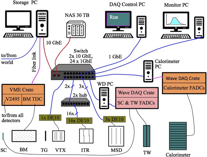
Battistoni et al.                                                                                                             The FOOT Experiment

materials, the nuclear fragmentation modifies the space radiation          applications in the proton-Nucleus (p-N) collisions field, is an
spectra, producing of secondary fragments that contribute to the          exceptionally challenging task because of the very short range of
dose release. This process has to be taken into account when              the produced fragments that results in a very low probability of
designing the proper shield to reduce the dose delivered to               escaping the target. Their range is limited to tens of microns and
astronauts and to prevent damages to the electronic systems               even a very thin solid target would stop them or badly spoil their
and instrumentations [24]. Dose estimates can be obtained, with a         energy measurement.
limited precision, through direct measurements, but the main                  Target fragmentation cross sections will be hence measured
tools available for the planning task are calculations with               using an inverse kinematic approach, studying the interactions of
deterministic and Monte Carlo transport codes [26]. An                    different ion beams (like 12C and 16O) impinging on hydrogen
essential ingredient for validating and benchmarking the                  enriched targets, such as C2H4, with an energy in the 50-
simulation results is the comparison with the measured                    200 MeV/nucleon range. The p-N cross sections will be
nuclear fragmentation cross sections for the interaction of the           therefore computed using the data collected using C2H4 and C
space primary ion components on different types of shielding              targets by means of a subtraction method whose feasibility has
[27]. Light materials, rich in hydrogen, are now considered as best       been already shown by the authors of refs. [31, 32].
shielding candidates and are preferred to aluminium, the material             When the projectile nucleus (12C or 16O) collides with a H
currently used to build most spacecraft structures. While the mass        nucleus of the target, the projectile fragments in the laboratory
stopping power (depending on Z/A) is maximized for light                  frame can be seen (applying a suitable Lorentz boost) as the
elements, the nuclear interaction cross section (proportional to          products of a process where a p collides onto a C or O target
σ/A) is minimized, reducing to a minimum the yield of neutrons            nucleus, but can be more easily measured. While the process of
produced in the interaction with the shield [24, 25]. Low Z, and          boosting the fragments in the reference frame in which the patient
especially liquid hydrogen, are hence among the most effective            is at rest is a procedure that implies some additional uncertainties
materials to be used to build shielding structures for space              (related to the limited precision achievable on the physical
applications [28]. While liquid hydrogen is not a suitable                quantities used to perform the Lorentz boost), the proposed
practical choice, being a low temperature liquid, shielding               method allows to perform the differential cross section
structures can be built using hydrogen stored in graphite                 measurements that would have been impossible otherwise.
nanofibers or lithium hydride compounds (6LiH). So far,                        A detector capable of performing the target fragmentation
polyethylene has been extensively studied and is regarded as a            measurement using the inverse kinematic approach can as well
good compromise between the achieved performance and                      perform the direct measurement of projectile fragmentation cross
easiness of practical integration with the spacecraft structure.          sections induced by C, He and O beams. The targets are the same
    Summarizing, there is a common ground between protecting              (graphite and polyethylene) both for PT applications and to
the astronauts from the harmful effects of space radiation and            explore the higher incoming beam energy range for RPS in
improving the tumor therapy planning of patients treated with             deep space applications. Using additional target materials, like
protons and ions. The particle species currently available in PT          polymethyl methacrylate (PMMA, C5O2H8), also other nuclei of
(protons and 12C) or considered as promising alternative                  interest for biological effects, like oxygen, can be studied. A
candidates (4He, 16O) are among the most abundant in space.               summary of the physics program of FOOT is reported in Table 1.
The overlap is also in terms of targets (H and C) and energy,                 The most stringent requirements on the precision that FOOT has
especially in the region of interest for tumor therapy applications       to reach are driven by the study of the target fragmentation process.
that is the same of solar flare protons and Van Allen trapped                  The final goal of the FOOT experiment is to measure
protons and is placed near the peak of the GCR spectrum.                  differential cross sections with respect to the kinetic energy
    In this landscape the FOOT (FragmentatiOn Of Target)                  (dσ/dEkin) for the target fragmentation process with an
collaboration has the purpose of performing precise                       accuracy better than 10% and double differential cross sections
measurements of differential fragmentation cross sections, with           (d2σ/dΩ·dEkin) for the projectile fragmentation process with an
respect to the emitted fragment kinetic energy and production             accuracy better than 5% on the determination of the fragment
angle [29, 30]. The FOOT measurements campaign foresees an                yields in angle and in kinetic energy.
extensive program focused on the nuclear fragmentation of 4He,                To achieve these performances the charge and isotopic
12
   C and 16O beams impinging on thin C and H rich targets, like           identification capability of the fragments should reach the level
polyethylene C2H4, in the energy range 100-800 MeV/nucleon, of            of 2–3% and 5% precision respectively, in order to have a clear
interest for PT and radioprotection in space (RPS) applications.          separation of all the isotopes under study. Such requirements
                                                                          become particularly difficult to match in the inverse kinematic
                                                                          approach, translating in a needed resolution on reconstructed
THE FOOT EXPERIMENT                                                       momentum and kinetic energy of the order of few percent and a
                                                                          resolution on the emission angle with respect to the beam
The FOOT experiment, funded by INFN (Istituto Nazionale di                direction of the order of few mrad. To minimize the multiple
Fisica Nucleare, Italy), has been designed to detect, track and           scattering impact and the probability of secondary fragmentation
identify all the charged fragments produced in ion collisions with        inside the target, its overall density weighted thickness has to be of
different targets, with the aim of measuring both projectile and          the order of 2-4 g/cm2, limiting the fragmentation probability
target fragmentation. The latter, which is of interest for                to ∼10−2.

Frontiers in Physics | www.frontiersin.org                            3                                    February 2021 | Volume 8 | Article 568242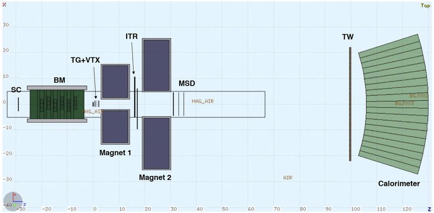
Battistoni et al.                                                                                                                                  The FOOT Experiment

TABLE 1 | FOOT physics program: in the last column the interaction processes to be studied for a given combination of beam, target, energy and kinematic approach
are shown.

Physics                         Application field            Beam                  Target                Upper Energy               Kinematic               Interaction
                                                                                                        (MeV/nucleon)              approach                  process

                                                             12
Target fragmentation                  PT                         C           C,C2H4                           200                  inverse               p+C
                                                             16
Target fragmentation                  PT                         O           C,C2H4                           200                  inverse               p+C

Beam fragmentation                    PT                     4
                                                              He             C, C2H4, PMMA                    250                  direct                α+C, α+H, α+O
                                                             12
Beam fragmentation                    PT                        C            C, C2H4, PMMA                    400                  direct                C+C, C+H, C+O
                                                             16
Beam fragmentation                    PT                       O             C, C2H4, PMMA                    500                  direct                O+C, O+H, O+O

Beam fragmentation                    Space                  4
                                                              He             C, C2H4, PMMA                    800                  direct                α+C, α+H, α+O
                                                             12
Beam fragmentation                    Space                     C            C, C2H4, PMMA                    800                  direct                C+C, C+H, C+O
                                                             16
Beam fragmentation                    Space                    O             C, C2H4, PMMA                    800                  direct                O+C, O+H, O+O

  FIGURE 1 | MC calculation [33, 34] of the angular (Left) and kinetic energy (Right) distributions of different fragments produced by a 200 MeV/nucleon 16O beam
  impinging on a C2H4 target.

   A MC simulation of a 16O beam of 200 MeV/nucleon kinetic                             tracking detectors, together with some detector for particle
energy impinging on a C2H4 target has been implemented using                            identification.
the FLUKA code [33, 34] to design and optimize the detector. The                            However as seen in Figure 1 low mass fragments (Z < 3) are
results of such simulation in terms of fragments yields in angle                        emitted with a wide angular aperture and the necessary cost, size,
(Figure 1 (Left)) and in kinetic energy (Figure 1 (Right)) show                         and weight of a magnetic apparatus capable of tracking them with
that heavier fragments (Z > 2) are forward peaked within a polar                        the required precision would become impracticable in view of a
angle of x10° and with a kinetic energy per nucleon peaked                              “table top” setup design.
around the corresponding primary beam value. The light                                      The FOOT experiment will implement an “upstream region”
fragments, instead, have wider angular and kinetic energy                               composed by the pre-target detectors, that will be used to monitor
distributions. Such distribution have been considered when                              the impinging beam, and a region, including the target, for the
designing the experimental setup, as they have a strong impact                          tracking and the identification of the fragments that foresee two
on the detector geometrical acceptance.                                                 alternative and complementary setups:
   Another constraint for the FOOT experiment comes from the
request to have a “movable” detector capable of fitting the space                        1. a setup that implements a magnetic spectrometer, coupled
limitations set by the different experimental rooms where ion                              with detectors for tracking and detectors optimized for the
beams of therapeutic energies are available. The standard choice,                          identification of fragments heavier than 4He. Such setup covers
for a fixed target experiment like FOOT, would be a magnetic                                an angular acceptance up to a polar angle of about 10° with
spectrometer composed by a dipolar magnet and high precision                               respect to the beam axis;

Frontiers in Physics | www.frontiersin.org                                          4                                          February 2021 | Volume 8 | Article 568242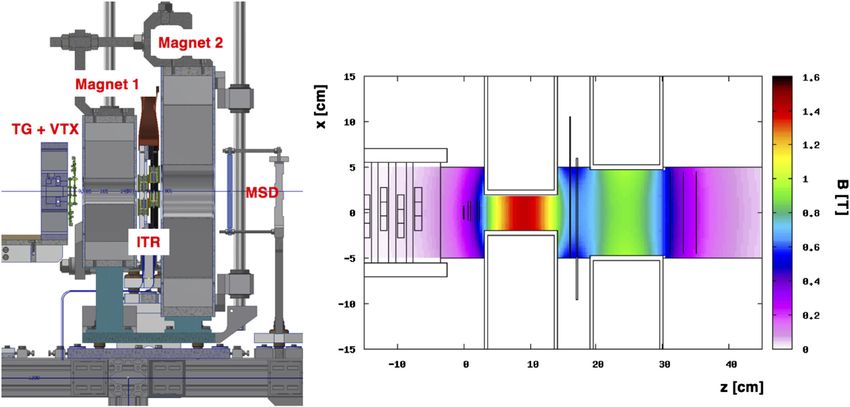
Battistoni et al.                                                                                                                                  The FOOT Experiment

  FIGURE 2 | Left: Start Counter detector inside the plastic box. The aluminum mechanical structure holds the EJ-228 plastic scintillator foil (in dark blue). Right:
  Technical drawing of the Beam Monitor drift chamber. The two orthogonal views x–y of the wires are clearly visible. Two enclosing mylar windows held by aluminum
  frames are shown as well.

2. a setup based on an emulsion spectrometer, optimized for low                        impinging ions. The overall material budget, crossed by the beam,
   Z fragments identification emitted at large polar angles that                        has to be minimised to reduce the out-of-target fragmentation, as
   will extend the angular acceptance of FOOT up to about 70°.                         well as the multiple scattering of the beam. The chosen
                                                                                       configuration foresees two detectors: the Start Counter, a thin
    The construction of the FOOT detector has started in 2018                          plastic scintillator read out by SiPMs, followed by the Beam
and will be completed by the end of 2020, allowing to take data in                     Monitor, a drift chamber, placed upstream of the target.
the following years. Most of the upstream region and of the
magnetic spectrometer detectors have already been built and                            The Start Counter
tested in different calibration campaigns at CNAO (Pavia,                              The Start Counter (SC) consists of a thin squared foil of EJ-228
Italy), TIFPA (Trento, Italy) and GSI (Darmstadt, Germany),                            plastic scintillator 250 µm thick. The foil has an active surface
with different ion beams of different energies. In the following                       with a 5 cm side that is sufficient to cover the typical beam
sections a general description of these detectors will be provided.                    transverse size (see Figure 2 (Left)) and is held by means of an
A detailed review of the technologies employed by the detectors                        aluminum frame enclosed in a black 3D printed box to provide
and their measured performances will be reported in dedicated                          the light tightness needed for the detector operation. In the black
papers, whereas some of them have been already published [35].                         box, two squared windows are placed in correspondence of the
    Fragmentation cross section measurements using carbon                              scintillator field of view and closed with a thin layer of 4 µm
beams impinging on different thin targets in the energy range                          aluminized mylar.
115–353 MeV/nucleon have been performed studying fragments                                 The light produced in the scintillator is collected laterally by 48
emitted at large angles. Such preliminary studies [36] have been                       (AdvanSiD ASD-NUV3S1) 3 × 3 mm2 SiPMs, 12 per side,
performed with an experimental setup very far from the final,                           bundled in eight electronic channels, each reading a chain of 6
optimised, one.                                                                        SiPMs. The readout and powering of the SiPMs is handled by the
    Tests carried out at LNS of the FOOT emulsion chambers have                        WaveDAQ system [38], capable of sampling signals at rates up to
already proved their capability in achieving the required FOOT                         5 Gsamples/s in a dynamic range of 1 V. A gain between 0.5 and
performances in charge separation [37]. Measurements with the                          100 can be applied to the incoming signal before digitization
full emulsion chamber setup have been already performed at GSI                         allowing to optimise the detector response in case of different
in 2019 and 2020 using 16O beams of 200 and 400 MeV/nucleon                            beam types or energies. In this way it is possible to maximise the
kinetic energy and a 12C beam of 700 MeV/nucleon kinetic energy                        detector efficiency compensating for the low light signal released
impinging on C and C2H4 thin targets. The ongoing analysis will                        due to the scintillator thinness.
be the subject of a dedicated paper.                                                       The acquired waveforms are analyzed offline with a constant
                                                                                       fraction discriminator technique to extract the event time t0.
The Upstream Region
The upstream region is composed of pre-target detectors that will
be used to monitor the beam, providing its direction and the
interaction point on the target, and to count the number of                            1
                                                                                           http://advansid.com/products/product-detail/asd-rgb-nuv-3s-p.

Frontiers in Physics | www.frontiersin.org                                         5                                           February 2021 | Volume 8 | Article 568242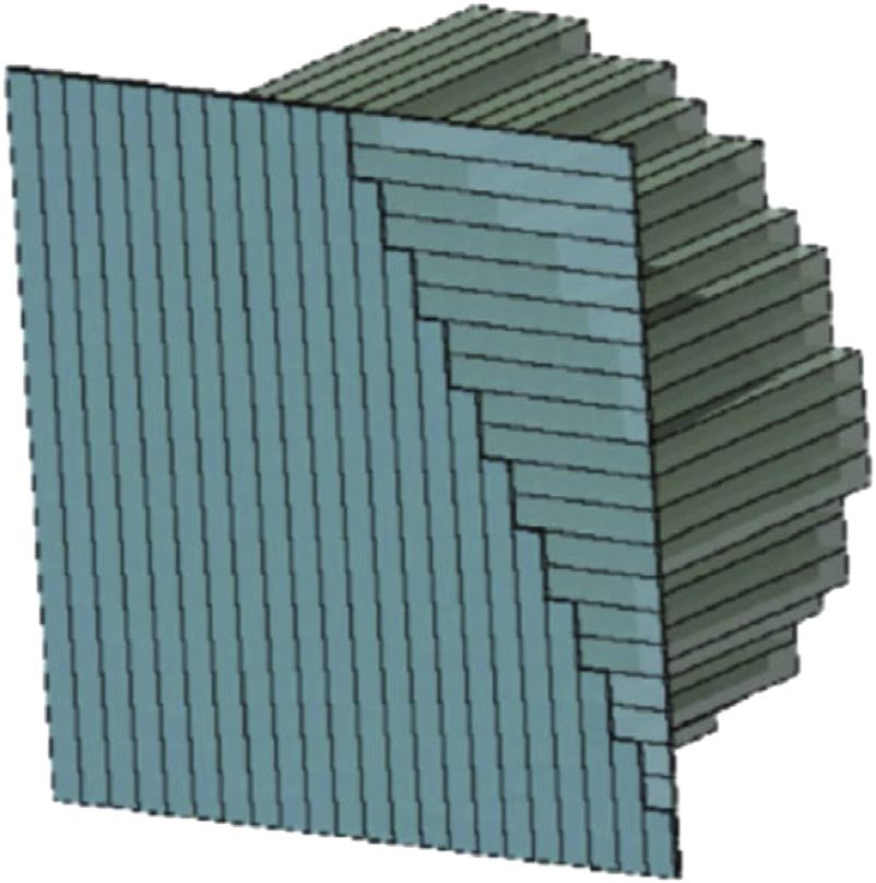
Battistoni et al.                                                                                                                  The FOOT Experiment

  FIGURE 3 | Schematic view of the upstream region and the Magnetic Spectrometer setup.

    The SC, placed upstream of the BM and of the target, fulfills                 impinging point of the beam ions on the target, a crucial
four main tasks: it provides the Minimum Bias trigger of the                     information needed to address the pile-up ambiguity in the
experiment, measures the incoming ion flux (with an efficiency                     tracking devices downstream the target and to discard events
>99%), provides the reference time for all the other detectors and               in which the beam has fragmented in the SC producing one or
it is used to perform the Time-Of-Flight (TOF) measurement in                    more deviated tracks. In order to reject pile-up vertices, an
combination with the TOF-detector (called Tof Wall, TW, see Tof                  high precision alignment is required between the BM and the
Wall Detector). A time resolution of the order of σ t x 60 ps has                devices downstream the target. The BM high spatial
been measured using a 12C beam of 700 MeV/nucleon kinetic                        resolution is fundamental to measure the direction of the
energy at GSI. Different thicknesses (ranging from 250 µm to                     fragments with respect to the beam with an accuracy of few
1 mm) can be used to monitor different beam projectiles and                      mrad, needed to measure the kinetic energy of the fragments
energy range combinations, in order to preserve the SC high                      in inverse kinematic with the required resolution. Finally, the
performances in terms of efficiency and time resolution. A                        BM information about the beam spot size is essential,
different Start Counter, developed within the FIRST experiment                   particularly in the case of the emulsion spectrometer, to
[17, 39], made with the same plastic scintillator, 250 µm thick, but             monitor the very low intensity beams used for the FOOT
read by PMT, has been used for the Emulsion chamber setup                        acquisitions (see Section Trigger and Data Acquisition
characterization so far as time performances were not requested                  System), whereas the monitoring performed with the
(see Section The Emulsion Spectrometer, Figure 10 (Left)) and the                standard facilities devices, especially in centers for patients
detector was only used to count the incoming ions.                               treatment, usually cannot provide the required accuracy and
                                                                                 resolution at such low rates.
The Beam Monitor
The Beam Monitor (BM), already used in the FIRST experiment                      The Magnetic Spectrometer
[17], is a drift chamber consisting of twelve wire layers, with three            The driving criterion of the FOOT detector design is the need for
drift cells per layer (see Figure 2 (Right)). Planes with wires                  an accurate charge and isotopic identification of the produced
oriented along the x and y axes are alternated allowing the beam                 fragments. To achieve the experimental goals a redundancy in
profile reconstruction in both views. The cell shape is rectangular               measuring the different kinematic variables is needed, exploiting
(16 mm × 10 mm). In each view, two consecutive layers are                        different particle identification (PID) techniques. For this reason
staggered by half a cell to solve left-right ambiguities in track                the FOOT setup includes a Time-Of-Flight (TOF) system and a
reconstruction [39]. New studies of BM working operations and                    calorimeter for the fragments energy measurement, that,
achievable performances have been done in the context of the                     combined with the measurement of the energy released in thin
FOOT experiment. The BM operates at x0.9 bar with a 80/20%                       detectors and with the information provided by the magnetic
gas mixture of Ar/CO2, at a working point ranging between 1850                   spectrometer, allows the isotope mass identification. The charge Z
and 2200 V, depending on the primary beam. A BM efficiency of                     of fragments reaching the TW can be identified from the energy
x90% has been measured, at the working point, for different                      loss ΔE and the TOF information, exploiting the Bethe-Bloch
combinations of ion beam and energies. A lower limit on the                      formula. The tracking through the magnetic field provides the
spatial resolution of 100 µm, in the central part of the BM cell, has            fragment rigidity (p/Z) and its path L that coupled with the
been achieved [40]. The BM detector will be placed between the                   measurement of TOF and Z provides the momentum p and the
SC and the target and will be used to measure the direction and                  velocity β · c  L/TOF of the particle. Finally the fragment mass

Frontiers in Physics | www.frontiersin.org                                   6                                  February 2021 | Volume 8 | Article 568242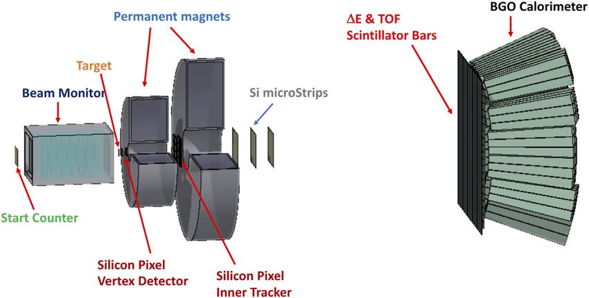
Battistoni et al.                                                                                                                                          The FOOT Experiment

  FIGURE 4 | (Left) Technical design of the interaction and tracking regions: the vertical axis is the y axis, while the horizontal axis is the z axis. The beam coming from
  the left, along the z-axis, cross sequentially the target (TG), the vertex detector (VTX), moves into the magnets region and crosses the Inner Tracker (ITR) and, immediately
  after the second magnet, passes through the Micro Strip Detetor (MSD). (Right) Computed magnetic field map produced by the FOOT magnets in Halbach
  configuration. The magnetic field intensity B, shown in the palette, is referred to its y-axis component.

identification can be achieved by momentum p, velocity β and
kinetic energy Ekin measurements using the following relationships:

   p  mcβc, Ekin  mc2 c − 1, Ekin  p2 c2 + m2 c4 − mc2 (1)

where γ is the Lorentz factor. Once the mass and the charge Z are
measured the fragment is uniquely identified.
   In order to match the precision requirements stated before on
the final cross section measurements, it will be necessary to
achieve the following experimental resolutions:

   •   σ(p)/p at level of 4-5%;
   •   σ(TOF) at level of 100 ps;
   •   σ(Ekin )/Ekin at level of 1-2%;
   •   σ(ΔE)/ΔE at level of 5%.

    The detector design has to keep the fragmentation contribution
due to the detector material as low as possible and should result in a
full apparatus sufficiently compact to be transported and installed in
the different facilities where 4He, 12C and 16O beams are available.                          FIGURE 5 | Schematic view of the fragment identification region. The
                                                                                              two orthogonal layers of 20 plastic scintillator bars are shown in front of the
The overall detector size should lie within the 2–3 m range. The                              matrix of BGO crystals used to build the calorimeter.
actual length of the setup will change according with the β of the
beam to allow an almost constant resolution on the fragment TOF.
Extensive FLUKA simulations (Figure 1) have been used to
optimise the transverse dimension of the detectors in order to fit                           shown in Figure 3. Three main regions can be identified in
the required angular acceptance, and their granularity studying the                         the experimental setup:
minimum separation angle between the emitted fragments.
    A schematic view of the final choice for the Magnetic                                    1. The upstream region, composed of the Start Counter and the
Spectrometer setup, together with the upstream region, is                                      Beam Monitor (see Section The Upstream Region).

Frontiers in Physics | www.frontiersin.org                                              7                                            February 2021 | Volume 8 | Article 568242
Battistoni et al. The FOOT Experiment
2. The interaction and tracking region, composed of the target where 960 discriminators are placed, one per column, each with a
followed by three stations of pixel and strip detectors placed configurable threshold level. The VTX readout has been
upstream, between and downstream of two permanent implemented by means of a DE10 board system housing an Intel
magnets providing the fragments production vertex and System-on-Chip (SoC) FPGA (Cyclon V) with a dual-core Cortex-
momentum measurement through the tracking in the A9 CPU. The FPGA is interfaced with the sensors and with the DAQ
magnetic field. control (trigger, time-stamping and busy signals) and the CPU is
3. The PID region, in the distal part of the detector located at least used to send data to the central DAQ via a 1 GbE connection. The
1 m away from the target. It is composed of two orthogonal kinematic inverse approach requires the beam particles direction
planes of thin plastic scintillator bars, providing the stop of the before the target and the fragment emission angle after the target to
TOF and the measurement of the energy loss ΔE. A BGO be tracked with an angular accuracy at the mrad level. The high
calorimeter, placed immediately after the TW, provides the spatial resolution of 5 µm achieved [45] with the VTX, matched with
fragment kinetic energy measurement. the information from the BM, can provide such angular resolution
while minimizing the multiple scattering thanks to the reduced
material budget of both BM and VTX.
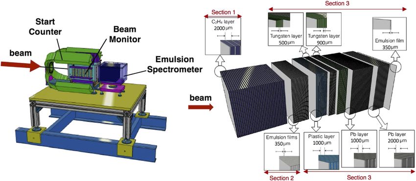
Interaction and Tracking Region
The overall tracking system of the FOOT experiment is conceived The magnetic System
as three measuring stations allocated upstream, between and A key element for the FOOT spectrometer is the magnetic system
downstream of two permanent magnets, as shown in Figure 4 used to bend the fragments produced in the target. The portability
(Left). The first tracking station is coupled to the target acting as of the system, when matched with the needed momentum
vertex detector (VTX) of the experiment. The needs in terms of resolution, forces the choice in the direction of having
momentum resolution and global acceptance together with the permanent magnets generating the needed (B × L) in a limited
minimization of multiple scattering and re-fragmentation in both sizes and weight, where B B(z) is the magnetic field intensity,
the sensors and the mechanical structures themselves suggest the strongly dependent on the fragment z-position, while L is the
use of monolithic pixel sensors in the two upstream stations, the length along the z-axis of the magnetic field region where the
VTX and the inner tracker (ITR), while a telescope of silicon particles experience the magnetic field effect and that can be
microstrip detectors (MSD) is envisaged for the downstream roughly assumed to be placed between the VTX and the MSD
station. In between the three stations two permanent magnets, trackers. A magnetic dipole in vacuum with two tracking stations
in Halbach configuration, provide the required magnetic field. placed upstream and downstream would ensure as well that the
needed momentum resolution is achieved, but is not a viable
Target and Vertex Detector solution to be implemented in a ‘portable’ table top experiment.
The target and the Vertex detector (VTX) are hosted in a The final choice is hence to have a magnetic system kept in air
mechanical structure designed to hold up to five different composed of two magnets, in Halbach configuration, which allow
targets in a sliding tray that can eventually be moved by a an additional tracking station in between the two needed to match
remote controlled actuator [17, 41]. The Vertex detector is the required momentum resolution. In the Halbach configuration
organized in 4 different pixel sensor layers of 2 × 2cm2 transverse an approximately dipolar magnetic field is obtained in the
dimension, placed along the z axis, respectively at 0.6-0.9-2.1–2.4 cm internal hole of a cylindrical permanent magnet. The magnetic
from the target center guaranteeing a geometrical acceptance of field increases with the external cylinder radius while decreases
about 40° for the emitted fragments. In order to fulfill the with the gap radius. So in order to match the final momentum
requirements of low material budget and high precision and resolution producing the needed (B × L) and at the same time
efficiency, the technology of the MIMOSA-28 (M28) Monolithic have an angular acceptance of 10° for the emitted fragments, two
Active Pixel Sensors (MAPS) has been adopted for each layer of the different magnet dimensions have been chosen. The first magnet
VTX. The M28 sensor, developed by the Strasbourg CNRS PICSEL has a gap diameter of 5 cm while the second one of 10.6 cm. They
group [42] for the upgrade of the vertex detector inner layer of the can provide respectively a maximum intensity of 1.4 T and 0.9 T
STAR experiment at RHIC [43, 44], consists of a matrix with 928 along the y axis in the internal cylindrical hole. The magnetic field
(rows) × 960 (columns) pixels of 20.7 µm pitch. The chip total size is intensity along the cylinder z axis exhibits a gaussian shape for
20.22 mm × 22.71 mm. The M28 sensor is implemented in the each magnet, according to the computed magnetic map shown in
AMS-C35B4/OPTO design process that uses 4 metal- and 2 poly- Figure 4 (Right): the inner tracker, sitting in-between the two
layers. The thickness of the epitaxial layer is 15 µm on a high magnets, will experience a field with an intensity of ∼0.6 T. Each
resistivity substrate of the order of 400 Ω·cm. All four M28 magnet will be made of twelve single units of Samarium-Cobalt,
sensors are thinned to 50 µm, resulting in an overall material which maintains its magnetic properties also in a high radiation
budget for the entire Vertex tracker of 200 µm. The architecture environments. The two magnets will be assembled in a single
of the M28 integrates a binary readout and a zero suppression in- mechanical structure sufficiently robust to withstand the
chip logic to reduce the amount of data transferred. Each pixel magnetic forces produced and to provide a high precision in
includes an amplification and a Correlated Double Sampling (CDS) the alignment with the tracking stations. Thanks to a detailed field
circuitry. The sensor employs a rolling shutter readout technique map, it will be possible to reach the intrinsic achievable accuracy
with a 185.6 µs frame readout time: all the pixels CDS output of one of about 10 µm. The capability of vertically displacing, of about
row are read out in parallel row by row at the end of the column 40 cm, the magnets with respect to the beam line, will give the
Frontiers in Physics | www.frontiersin.org 8 February 2021 | Volume 8 | Article 568242Battistoni et al. The FOOT Experiment
opportunity to inter-align the tracking stations in specific runs order to minimize the fragment pile-up in the same strip. Each
without the magnets, to adapt the setup to different experimental SSSD is readout by 10 VA1140 chips, with a readout pitch of
rooms and will ease the tracking detectors access and cabling once 150 µm, bonded and glued on the PCB, for a total of 640 channels.
the setup will be finally assembled. The front-end hybrids, hosting the readout chips, is glued at one
side of each silicon module minimizing the dead space in the
Inner Tracker beam region. A digital readout of the strips with pitch of 150 µm
The FOOT Inner Tracking (ITR) station foresees two planes of would provide a spatial resolution of x40 µm, while with the
pixel sensors to track the fragments in the magnetic region. In selected analog readout a further factor 3 can be gained, as shown
order to fit the required acceptance, granularity and tracking in [51, 52], with the additional advantage to measure also the dE/
performances each plane will cover a sensitive area of about 8 × dx, for each x-y view of each layer independently. The analog
8 cm2, with 16 M28 sensors per layer. The main reasons for such signals provided by the VA1140 readout chips are digitized by
choice are again the quest for the material budget reduction 1 MHz 12-bits ADC and their data are sent to a TERASIC DE10
together with the need of high tracking performances. nano board for data collection and event shipping to the general
Furthermore the tracking performances of M28 sensors are FOOT DAQ.
not expected to be significantly affected by the foreseen
residual magnetic field in between the permanent magnets Fragment Identification Region
[46]. In addition, by using the same technology implemented The fragment identification region is the distal part of the
by the VTX the architecture of the DAQ system will be simplified. detector, located at least 1 m away from the target. It is
Differently with respect to the VTX, the large detector area composed of two orthogonal planes of plastic scintillator bars
implies the use of a mechanical support, that results in an (Tof-Wall detector), providing the stop of the TOF and the
increase of the overall material budget. measurement of the energy loss, followed by a BGO
The ITR will be built using ladders similar to the ones calorimeter used to measure the fragment kinetic energy (see
implemented in the PLUME project [47]. The ITR ladder will Figure 5).
implement a double-sided layout, which consist of two modules
of M28-sensor layers glued on the opposite sides of a support Tof Wall Detector
structure, 2 mm thick, made of low density silicon carbide (SiC) The Tof-Wall detector (TW) is composed of two layers of 20
foam. Each module is composed of 4 M28 sensors glued and plastic scintillator bars (EJ-200 by Eljen Technology), arranged
bonded on a kapton-metal flex cable. The flex cables provide all orthogonally and wrapped with reflective aluminum and
the communications and services of the sensors from and to the darkening black tape [35, 53]. Each bar is 0.3 cm thick, 2 cm
outside world. The overall material budget of an ITR ladder is wide and 44 cm long. The two orthogonal x-y layers form a 40 ×
x/X0 x0.3%, where x and X0 are respectively the overall thickness 40 cm2 active area detector that provides the measurements of the
and radiation length of the ITR ladder. The ITR will be composed energy deposited ΔE, the needed information to compute the
of four ladders, two for each plane, supported by a metallic frame TOF (using as input the t0 from SC), and the hit position. The
to hold the entire tracker. While the described design is the final simultaneous measurement of ΔE and TOF allows to identify the
one, the detector still has to be fully assembled and tested. charge Z of the impinging ions [54, 55]. The Z-identification plays
a fundamental role in determining the fragment mass and is used,
Micro Strip Detector together with the x-y hit position, as a seed for the fragments
The fragments tracking downstream the magnetic region is tracking through the magnetic field. The TW transverse
essential for the measurement of momentum and for the dimensions have been chosen to match the angular aperture
matching of the reconstructed tracks with the hits in the TW of the heavy fragments at the distance of the detector from the
and in the calorimeter. This task is entrusted to a microstrip target (1–2 m) set by the experimental room conditions. The
silicon detector (MSD), that, operating with an analogue readout, chosen granularity keeps the pile-up of multiple fragments in the
can also provide a redundant measurement of dE/dx [48–50], for same bar below x1%. The thickness of the bar has been chosen as
fragments charge Z identification, complementary to the one a trade-off between a higher scintillation signal (reflecting in
performed by the TW. A tracking station of three MSD x-y planes better timing and energy resolution) and a lower secondary
with an active area of 9.6 × 9.3 cm2, separated by a 2 cm gap along fragmentation probability in the bars, that would spoil the
the beam direction and positioned right after the second magnet, particle identification and tracking.
ensure the needed angular acceptance to measure ions with Z > 2, Each of the two edges of the TW bars is coupled to 4 SiPM
as expected from the FLUKA simulation. In order to reduce the (MPPC S13360-3025PE2) with a 3 × 3 mm2 active area and 25 µm
amount of material and to provide the x-y coordinate readout, a microcell pitch. The signals of each channel (two channels per
solution exploiting two perpendicular Single-Sided Silicon bar) are digitized at rates of 3–4 Gsamples/s depending on the
Detector (SSSD) sensors thinned down to 150 µm has been trigger scheme adopted (see Section Trigger and Data Acquisition
adopted for each MSD x-y plane. Each sensor is glued on a System) by the WaveDAQ system [38] as described in Section The
hybrid Printed Circuit Board (PCB) that provides the needed Start Counter. A total of 1024 samples are collected for each signal
mechanical support and the interface with the MSD readout.
Light tightness of each plane is ensured using the metallized
sensors backplane. A strip pitch size of 50 µm has been chosen in 2
https://www.hamamatsu.com/resources/pdf/ssd/s13360_series_kapd1052e.pdf.
Frontiers in Physics | www.frontiersin.org 9 February 2021 | Volume 8 | Article 568242Battistoni et al. The FOOT Experiment
FIGURE 6 | DAQ logical scheme.
allowing to record the whole waveform, and to extract offline the time up to 200 MeV/nucleon. In this energy range, the main
and the charge information. The thickness of the bars and the selected mechanism of energy loss is by far through electromagnetic
readout chain, have been chosen to meet the FOOT requirements of a interaction with the target electrons and nuclei. In that case a
TOF resolution better than 100 ps and an energy loss resolution proper containment of the fragments can be achieved allowing to
σ(ΔE)/ΔE x 5%, for the heavier fragments [35]. Thanks to the high maximise the energy resolution. In all cases, however, it shuold be
number (4 × 14400) of pixels per channel of the SiPM, this setup is noted that for a fraction of the events neutron production takes
able to guarantee a dynamic range spanning over two orders of place and part of the fragment energy escapes the detector,
magnitude and allow the identification of fragments with significantly causing a systematic error that spoils the energy resolution.
different energy release (from proton to oxygen with different kinetic The impact of such effect can be minimised exploiting the
energies). Finally, the high precision time measurement can be used to redundant information coming from the other detectors. Since
reconstruct the hit position along the bar [35] with a precision σpos < FOOT will work at a relatively low beam intensity, the ideal
8 mm, better than the one achievable only exploiting the information material for a calorimeter is a dense crystal, with high light yield,
about the bars crossing, an important information used to reduce the without strict requirements on the response speed: BGO was
combinatorial association of multiple fragments in the front and rear identified as the best candidate providing the needed
side of the TW in the offline reconstruction. performance, on one side, while easing the matching with the
mechanical constraints and the overall cost on the other. The high
Calorimeter density of this material (ρ 7.13 g/cm3) guarantees a high
The FOOT calorimeter is the most downstream detector and it is stopping power, that, coupled to a light yield of x10 photon/
designed to measure the fragments kinetic energy needed to keV, meets the requirements on the energy resolution. The FOOT
compute their mass A. Depending on the energy of the calorimeter will be composed of 320 Bi4Ge3O12 (BGO) crystals
incoming fragment, different phenomena can take place in the positioned with an approximately disk-like arrangement
calorimeter in the energy range of interest for the FOOT (x20 cm radius) and mechanically divided in modules of 3 ×
experiment. At the highest energies, x700–800 MeV/nucleon, 3 crystals, in order to best handle their weight and positioning.
that will be explored in the context of space radiation protection The crystals have a truncated pyramid shape with a front (back)
studies, the pion production threshold is exceeded and hadronic face of about 2 × 2 cm2 (3 × 3 cm2) and a length of 24 cm. The
showering takes place. In these conditions a full containment BGO crystal transverse size is similar to the TW granularity. The
cannot be achieved with affordable calorimeter dimensions, and probability of pile-up in the same crystal due to multi-
this results in a worsening of the achievable resolution at these fragmentation events is kept below x1–2%, depending on the
energies. On the other hand, the highest resolution is needed for beam energy/experimental room setup configuration. The crystal
the case of target fragmentation studies, that involves 12C and 16O depth has been chosen in order to minimize the energy leakage
Frontiers in Physics | www.frontiersin.org 10 February 2021 | Volume 8 | Article 568242Battistoni et al. The FOOT Experiment
mainly due to neutrons escaping the calorimeter. Each BGO The system control will be hosted on a controller PC used to
crystal is coupled to a 25 SiPMs matrix with an active surface of run the DAQ GUI interface to start/stop a single run, to control
2 × 2 cm2, where each microcell has a pitch of 15 µm, small and to configure other nodes in the system. Another PC (Storage
enough to have a linear response in the energy range up to about PC) will be used to collect the information coming from the
10 GeV. Each SiPM matrix is coupled to a readout board different detectors, to perform an event building and to store on
specifically designed to match the dimensions of the SiPMs, disk the acquired data. On the same PC, a MYSQL DataBase (DB)
ensuring a very compact design of the overall detector. The will have the role to store the configuration data (structured DB
Front-end board will be interfaced with the WaveDAQ system, tables or in form of retrievable text files) and to store the DAQ
the same readout system used for SC and TW detectors [38], that process information (start/stop DAQ time, events collected, other
will sample the signal at 1 Gsample/s, allowing a measurement based global DAQ information). An electronic logbook interfaced with
on both the signal amplitude and its integral, as well as a shape the DAQ system will be installed on the same machine.
analysis. The same board is used to readout the SiPM temperature The steering of the acquisition process and the reading of the other
sensor, useful to compensate the variation of the system response nodes will be managed through an ethernet switch connected via a 10
caused by temperature variations and to equalize the calorimeter GbE cable and a CAEN V27184 VME to PCI Optical Link Bridge. The
response offline. Several beam tests have been performed in a wide switch is used to collect all the data from the detectors via 1Gbps
energy range (from 70 MeV protons to 400 MeV/nucleon 12C), in ethernet connections: the whole tracking system (VTX, ITR and
order to choose the optimal combination of SiPM array, readout MSD), based on 20 DE10-nano or DE10 Terasic boards, the time
configuration and BGO wrappings. A very good linearity response is of flight system (SC and TW) and the calorimeter based on the
achieved in the whole investigated energy range and the measured WaveDAQ system. The DE10-nano boards have an FPGA for
energy resolution σ(Ekin )/Ekin below 2% meets the experiment detector reading and a dual core ARM cortex 9 processor for
requirements for the heavier fragments [56, 57]. event formatting, zero suppression and data shipping via ethernet.
The WaveDAQ boards for the TOF system and for the calorimeter
Trigger and Data Acquisition System send its data to intermediate PCs providing data calibration,
The FOOT detector will be equipped with a DAQ system compression and data shipping. The VME to PCI Optical Link
designed to acquire the data with high accuracy in a Bridge in the storage PC is connected to a VME crate holding the
controlled and online-monitored environment. trigger board V2495 and the Beam Monitor discriminators and TDC
The main experiment trigger (Minimum Bias) will be based on board CAEN V1190B. The expected typical event size is of the order of
signals provided by the SC and will be fired whenever the multiplicity 30 kB, but can be increased if needed up to 100 kB. The availability of
of the channels above thresholds exceeds a programmable value RAM memories along the data collection paths (in the FPGAs, in the
(majority trigger). This choice minimise the source of systematic DE10, in the PCs, in the switch and in the CAEN boards) allows an
uncertainties on the cross section measurements due to the events almost complete decoupling of the trigger signal time from the event
trigger selection. A fragmentation trigger asking for activity outside building time in the storage PC that can happen several seconds apart,
the central bars of the TW in a logical OR can also be used, in while still keeping an average DAQ rate of 1 kHz (with rate peaks of
addition to a prescaled Minimum Bias trigger, to enhance the 5 kHz). The whole system is designed to store data on a SSD disk (max
fraction of recorded fragmentation events. The technology that rate 400 MB/s) during data taking and to transfer the data to a dedicated
will be used to implement the trigger is provided by a CAEN (>20 TB) NAS system during idle times. The DAQ system will be
V2495 board3, whose FPGA and internal logic is fully equipped with a set of online monitoring tools. The DAQ running
programmable. The maximum acquisition rate affordable when related information can be easily collected from each VME board or
operating with a Minimum Bias trigger would depend on the data provider at a rate ∼Hz, depending on the specific sub-detector
slowest detectors in the experiment. These are the MIMOSA 28 system, and provided to a network of PCs connected to the experiment.
chips used in the pixel trackers (VTX and ITR), which have a frame Typical online monitoring histograms based either on local or
readout time of 185.6 µs, needed to read about 106 pixels per chip. distributed data will show detector occupancy, particle arrival times,
The overall maximum readout rate would be hence of about Rmax particle energies, collected charges and so on. The online monitoring
5 kHz. The system will be designed to handle a maximum DAQ rate foresee also a fast online event reconstruction performed, on the fly, on a
of Rdaq Rmax, but in order to reduce pile-up effects in the MIMOSA fraction of the events. Performing a complete event reconstruction it will
chips the actual trigger rate will be of the order of Rtrigger 1 kHz. be possible to monitor the fragments momentum spectra, TOF,
With this rate, considering a duty cycle of fdc 30%, during stable reconstructed charges and masses.
running conditions, up to Nday x 86400·1k·0.3 26 M events per
day can be collected with a Minimum Bias trigger.
The DAQ system that will be implemented for the whole MC Simulation and Fragment Identification
apparatus is a flexible hierarchical distributed system based on Performances
linux PCs, VME crates and boards, detector integrated readout Detailed MC simulations with the FLUKA software [33, 34] have
systems and standard communication links like ethernet, USB been developed for different combinations of ion beams, beam
and optical fibers, schematized in Figure 6. kinetic energy and targets, in order to optimize the detector
3 4
https://www.caen.it/products/v2495/ https://www.caen.it/products/v2718/
Frontiers in Physics | www.frontiersin.org 11 February 2021 | Volume 8 | Article 568242Battistoni et al. The FOOT Experiment
FIGURE 7 | 2-D top view of the full FOOT setup geometry implemented in the FLUKA MC simulation.
FIGURE 8 | (Left) Fragments charge identification in TW using the energy release in the scintillators ΔE and the TOF calculation performed together to the SC. For
each region a Bethe-Bloch curve (shown as a different black curve), parametrized as a function of TOF, has been used to fit the MC simulation results to describe the
average energy loss of fragments of the same charge Z impinging on TW with different angles, kinetic energies, TOF and path lenghts L. (Right) An example of mass
number determination obtained with the χ 2 fit for the carbon fragments for the case of σ(TOF) x 70 ps, σ(p)/px3.7% and σ(Ekin )/Ekin x1.5%. The 11C, 12C and
13
C isotopes are clearly visible.
design and evaluate its expected performances taking into out-of-target fragmentation processes. Care has been taken in
account the constraints set by the different experimental detailing at the highest possible degree the different detector
rooms where FOOT will acquire data. The full detector subsystems to evaluate with high accuracy the acceptances,
geometry and materials, already described in Section The efficiencies and resolutions needed for the cross-section
Magnetic Spectrometer, have been implemented in the MC measurement.
simulation to properly evaluate the interactions in all the In the following, the results of a FLUKA simulation of a 16O
active detectors and the production of secondary particles in beam of 200 MeV/nucleon kinetic energy impinging on a 2 mm
Frontiers in Physics | www.frontiersin.org 12 February 2021 | Volume 8 | Article 568242Battistoni et al. The FOOT Experiment
FIGURE 9 | Mass resolution of the identified isotopes of carbon ions (9C, 10C, 11C, 12C , 13C, 14C) as a function of: A) kinetic energy resolution (σ(TOF) 70 ps and
σ(p)/p 3.7%) B) momentum resolution (σ(TOF) 70 ps and σ(Ekin )/Ekin 1.5%) C) carbon ions TOF (σ(p)/p 3.7% and σ(Ekin )/Ekin 1.5%).
thick C2H4 target are shown to document the expected in Figure 8 (Left) the TW resolution allows the discrimination of
performances of the magnetic spectrometer setup in terms of eight regions in the ΔE-TOF plane, related to different fragment
fragment identification [58, 59]. charges. For each region a Bethe-Bloch curve, parametrized as a
The 2-D top view of the full FOOT detector setup is shown in function of TOF, has been used to fit the MC simulation results to
Figure 7, in a geometrical configuration in which the distance between describe the average energy loss of fragments of the same charge Z
TG and TW is 1 m, compatible with most of the experimental rooms impinging on TW with different angles, kinetic energies, TOF
where FOOT experiment is expected to collect data. and path lenghts L. For each fragment the charge corresponding
The MC scoring provides the fundamental quantities related to the closest Bethe-Bloch curve in the ΔE-TOF plane is assigned.
to each FOOT detector sub-system: times in SC, fired cells in BM, The identification capability depends mainly on the ΔE
fired pixels in VTX and ITR detectors, energy released in MSD resolution, that, with the aforementioned values, implies a
strips, and time and energy released in TW bars and calorimeter fragment charge mis-identificationYou can also read