Magnetic drilling machine Model Number - PB50 LOW PROFILE 1 - G&J Hall Tools
←
→
Page content transcription
If your browser does not render page correctly, please read the page content below
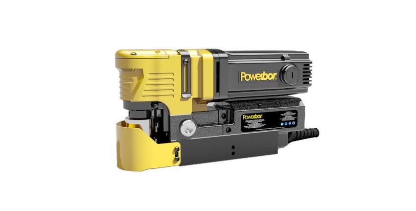
Magnetic drilling machine
                               Model Number
                            PB50 LOW PROFILE 1

         This machine (Serial Number ...........................) is CSA approved.

                                      G&J HALL
                              830 Hanley industrial court
                                     Brentwood
                                      Missouri
                                       63144

Tel: (314) 968-5040                                Fax: (314) 968-5040
Email: sales@gjhalltools.com            Website: www.gjhalltools.com
PB50 Low Profile Manual         Original instructions           2019

CONTENTS OF THE MANUAL
                                                                   Page

  1)    Intended use                                               3
  2)    General safety rules                                       3
  3)    Information plate symbols                                  4
  4)    Specification                                              5
  5)    Operational safety procedures                              6
  6)    Operating instructions                                     6
  7)    Extension cable selection                                  7
  8)    Mounting of cutters                                        7
  9)    Remedies for hole making problems                          8
  10)   Wiring diagram                                             9
  11)   Exploded view                                              10
  12)   Motor Breakdown                                            13
  13)   Control panel and parts list                               14
  14)   Pipe adapter kit RD2311                                    15
  15)   Maintenance                                                16
  16)   Trouble shooting                                           17
  17)   Cutter selection, speeds and feeds                         18
  18)   Additional warnings                                        19

         Part              Description                      Quantity
                RDF4030              4mm Hexagonal Wrench         2
                RDF4031                 Coolant Bottle            1
                RDF4032                 Ratchet Handle            1
                RD4329B                  Safety Strap             1
                RDF4033                 Safety Goggles            1
                RDF3005                Carbon Brush Set           1

   1)
   2) SE

                                                  2
PB50 Low Profile Manual Original instructions 2019
1) INTENDED USE
The intended use of this magnetic drill is to drill holes in ferrous metals. The magnet is used to hold the drill in place
whilst the drill is functioning. It is designed for use in fabrication, construction, railways, petrochemical and any other
applications when drilling ferrous metal.
Any deviation from its intended use will not be covered by warranty.
2) GENERAL SAFETY RULES
WARNING! Read and understand all instructions. Failure to follow all instructions listed below, may result in
electric shock, fire and/or serious personal injury.
SAVE THESE INSTRUCTIONS.
Work area
1.Keep your work area clean and well lit. Cluttered benchesand dark areas invite accidents.
2.Do not operate power tools in explosive atmospheres, suchas in the presence of flammable liquids, gases or
dust.Power tools create sparks which may ignite the dust orfumes.
3.Keep bystanders, children and visitors away while operatinga power tool. Distractions can cause you to lose control
Electrical safety
1.Grounded tools must be plugged into an outlet properly installed andgrounded in accordance with all codes and
ordinances. Neverremove the grounding prong or modify the plug in any way. Do notuse any adaptor plugs. Check
with a qualified electrician if you are indoubt as to whether the outlet is properly grounded. If the tools
shouldelectrically malfunction or break down, grounding provides a lowresistance path to carry electricity away from
the user.
2.Avoid body contact with grounded surfaces such as pipes, radiators,ranges and refrigerators. There is an increased
risk of electric shock ifyour body is grounded.
3.Don’t expose power tools to rain or wet conditions. Water entering apower tool will increase the risk of electric
shock.
4. Do not abuse the cord. Never use the cord to carry the tools or pull the plug from an outlet. Keep cord away from
heat, oil, sharp edges or moving parts. Replace damaged cords immediately. Damaged cords increase the risk of
electric shock.
5. When operating a power tool outside, use an outdoor extension cord marked” W-A” or” W”.These cords are rated
for outdoor use and reduce the risk of electric shock.
Personal safety
1. Stay alert, watch what you are doing and use common sense when operating a power tool. Do not use tool while
tired or under the influence of drugs, alcohol, or medication. A moment of inattention while operating power tools
may result in serious personal injury.
2. Dress properly. Do not wear loose clothing or jewelry. Contain long hair. Keep your hair, clothing, and gloves away
from moving parts. Loose clothes, jewelry, or long hair can be caught in moving parts.
3. Avoid accidental starting. Be sure switch is off before plugging in. Carrying tools with your finger on the switch or
plugging in tools that have the switch on invites accidents.
4. Remove adjusting keys or switches before turning the tool on. A wrench or a key that is left attached to a rotating
part of the tool may result in personal injury.
5. Do not overreach. Keep proper footing and balance at all times. Proper footing and balance enable better control of
the tool in unexpected situations.
6. Use safety equipment. Always wear eye protection. Dust mask, non-skid safety shoes, hardhat, or hearing
protection must be used for appropriate conditions.
Tool use and care
1.Use clamps or other practical way to secure and supporttheworkpiece to a stable platform. Holding the work by
3PB50 Low Profile Manual Original instructions 2019
hand or againstyour body is unstable and may lead to loss of control.
2.Do not force tool. Use the correct tool for your application. Thecorrect tool will do the job better and safer at the
rate for which it isdesigned.
3.Do not use tool if switch does not turn it on or off. Any tool thatcannot be controlled with the switch is dangerous
and must be repaired.
4.Disconnect the plug from the power source before makinganyadjustments, changing accessories, or storing the
tool. Suchpreventive safety measures reduce the risk of starting the toolaccidentally.
5.Store idle tools out of reach of children and other untrainedpersons. Tools are dangerous in the hands of untrained
users.
6.Maintain tools with care. Keep cutting tools sharp and clean.Properly maintained tools, with sharp cutting edges are
less likely to bindand are easier to control.
7.Check for misalignment or binding of moving parts, breakage ofparts, and any other condition that may affect the
tools operation. Ifdamaged, have the tool serviced before using. Many accidents arecaused by poorly maintained
tools.
8.Use only accessories that are recommended by the manufacturerfor your model. Accessories that may be suitable
for one tool, maybecome hazardous when used on another tool.
Service
1.Tool service must be performed only by qualified repair personnel.Service or maintenance performed by unqualified
personnel could result in arisk of injury.
2.When servicing a tool, use only identical replacement parts. Followinstructions in the Maintenance section of this
manual. Use ofunauthorized parts or failure to follow Maintenance Instructions may createa risk of electric shock or
injury.
WARNING!
Always use safety chain. Mounting can release.
3) INFORMATION PLATE SYMBOLS
1 2 3 4
1. Refer to the user manual for operational and safety issues with regard to this machine.
2. Dispose of the machine and electrical components correctly.
3. Eye protection must be worn when operating the machine.
4. Ear defenders must be worn when operating the machine.
4PB50 Low Profile Manual Original instructions 2019
4)SPECIFICATION
Maximum hole cutting capacity in .2/.3C steel = 2” dia. x 2” deep
Arbor bore = 3/4" dia.
Motor Unit
Voltages 120V 50-60Hz 230V 50-60Hz
Normal full load 10 A 6A
Electro Magnet 0.53 A 0.28 A
Size 7 -9/16” long
3-1/8” wide
Holding Force at 20°C with 25mm 2250 lbs
minimum plate thickness
The use on any material less than 25mm thick will progressively
reduce the magnetic performance. If possible, substitute
material should be positioned under the magnet and work
piece to equate to a suitable material thickness. If this is not
possible, an alternative secure method of restraining the
machine MUST be used.
Overall Dimensions
Height - minimum 7 – 1/16”
Width (including Capstan fitting) 3 – 15/16”
Length Overall (including Guard) 13 – 1/8”
Nett Weight 24 lbs
PB50 LOW PROFILE PB50 LOW PROFILE
1 3
Vibration total values (triax vector sum) in accordance with Vibration emission value Vibration emission value
EN62841-1:
Level of sound pressure in accordance with EN62841-1:
Ear and eye defenders must be worn when operating this machine. Wear gloves to protect hands when operating the
machine.
These tools are UK designed and manufactured with globally sourced components and conform to the requirements of
EEC Document HD.400.1 and BS.2769/84
Suitable only for a single phase 50-60Hz A.C. power supply
DO NOT USE ON D.C. SUPPLY
Do not use your magnetic drill on the same structure when arc welding is in progress.
D.C. current will earth back through the magnet and cause irreparable damage.
WARNING: THIS APPLIANCE MUST BE EARTHED!
NB: ANY MODIFICATIONS TO THIS MACHINE WILL INVALIDATE THE GUARANTEE
5PB50 Low Profile Manual Original instructions 2019
5) OPERATIONAL SAFETY PROCEDURES
READ BEFORE USING THE MACHINE
• When using electrical tools, basic safety precautions should always be followed to reduce the risk of electric shock, fire, and personal injury.
• Ensure the magnet is OFF before plugging in the machine.
• Do NOT use in wet or damp conditions. Failure to do so may result in personal injury.
• Do NOT use in the presence of flammable liquids, gases or in high risk environments. Failure to do so may result in personal injury.
• BEFORE activating the machine, inspect all electrical supply cables (including extension leads), and replace if damaged. DO NOT use if there are
any signs of damage.
• Only use extension cables approved for site conditions.
• BEFORE activating the machine, ALWAYS check the correct function of all operational systems, switches, magnet etc.
• BEFORE operating, the machine MUST be securely restrained to a fixed independent feature (by using safety strap RD4329B, or other means) to
reduce the potential free movement, should the magnet become detached from the work piece. Failure to do so may result in personal injury.
• ALWAYS wear approved eye protectors, ear defenders and recommended PPE at ALL times when operating the machine.
• Disconnect from power source when changing cutters or working on the machine.
• Cutters and swarf are sharp, ALWAYS ensure that hands are adequately protected when changing cutters or removing swarf. Use a tool or brush
where necessary to remove any swarf or the cutter from the arbor.
• Before operating the machine, ALWAYS ensure cutter-retaining screws are secured tightly.
• Regularly clear the work area and machine of swarf and dirt, paying particular attention to the underside of the magnet base.
• ALWAYS remove tie, rings, watches and any loose adornments that might entangle with the rotating machinery before operating.
• ALWAYS ensure that long hair is securely enclosed by an approved restraint before operating the machine.
• Should the cutter become stuck in the work piece, stop the motor immediately to prevent personal injury. Disconnect from power source and
turn arbor to and fro. DO NOT ATTEMPT TO FREE THE CUTTER BY SWITCHING THE MOTOR ON AND OFF. Wear safety gloves to remove the
cutter from the arbor.
• If the machine is accidentally dropped, ALWAYS thoroughly examine the machine for signs of damage and check that it functions correctly
BEFORE resuming drilling.
• Regularly inspect the machine and check for any damaged or loose parts.
• ALWAYS ensure when using the machine in an inverted position that only the minimum amount of coolant is used, and that care is taken to
ensure that coolant does not enter the motor unit.
• Cutting tools may shatter, ALWAYS position the guard over the cutter before activating the machine. Failure to do so may result in personal
injury.
• On completion of the cut, a slug will be ejected. DO NOT operate the machine as the ejected slug may cause injury.
• When not in use ALWAYS store the machine in a safe and secure location.
• ALWAYS ensure that approved POWERBOR™ agents conduct repairs.
6) OPERATING INSTRUCTIONS
• Keep the inside of the cutter clear of swarf. It restricts the operating depth of the cutter.
• Ensure that the coolant bottle contains sufficient cutting oil to complete the required operating duration. Refill as required.
• Occasionally depress the pilot to ensure cutting fluid is being correctly metered.
• To start the machine, follow the control panel operation instructions.
• ALWAYS switch off the motor by depressing the MOTOR stop button. DO NOT switch off the motor by depressing the MAGNET switch.
• Apply light pressure when commencing the cut of a hole until the cutter is introduced into the work surface. Pressure can then be increased
sufficiently to load the motor. Excessive pressure is undesirable, it does not increase the speed of penetration and will cause the safety overload
protection device to stop the motor, (the motor can be restarted by operating the motor start button), and may cause excessive heat which
may result in inconsistent slug ejection
• Always ensure that the slug has been ejected from the previous hole before commencing to cut the next.
• If the slug sticks in the cutter, move the machine to a flat surface, switch on the magnet and gently bring the cutter down to make contact with
the surface. This will usually straighten a cocked slug and allow it to eject normally.
• Apply a small amount of light oil lubricant regularly to the slide and arbor support bearing.
• Cutter breakage is usually caused by insecure anchorage, a loosely fitting slide or a worn bearing in the arbor support. (Refer to routine
maintenance instructions).
• Only use approved cutting fluid.
6PB50 Low Profile Manual Original instructions 2019
7) EXTENSION CABLE SELECTION
The machines are factory fitted with a 2yard length of cable having three conductors 2.08mm²
LIVE, NEUTRAL and EARTH. If it becomes necessary to fit an extension cable from the power source, care must be
taken in using a cable of adequate capacity. Failure to do so will result in a loss of traction by the magnet and a
reduction of power from the motor.
If the replacement of the supply cord is necessary, this has to be done by the manufacturer or an approved agent in
order to avoid a safety hazard.
Assuming a normal AC supply of the correct voltage, it is recommended that the following extension lengths shall not
be exceeded:
For 120v supply: 3.5metres of 3 core x 2.08mm²(14AWG)
For230v supply: 26 yards of 3 core x 1.5mm²
ALWAYS DISCONNECT THE MACHINE FROM THE POWER SOURCE BEFORE CHANGING CUTTERS.
8) MOUNTING OF CUTTERS
• The machine has been made to accept cutters having 3/4”dia. Weldon shanks.
The following procedure is to be used when mounting cutters:
• Lay the machine on its side with feed handles uppermost, ensuring arbor is wound down to its lowest point to
enable access to socket screws.
• Take appropriate pilot and place through the hole in cutter shank. Insert shank of cutter into bore of arbor,
ensuring alignment of two drive flats with socket screws.
• Tighten both screws using hexagon key.
STAN OPERATION
7PB50 Low Profile Manual Original instructions 2019
9) REMEDIES FOR HOLE MAKING PROBLEMS
Problem Cause Remedy
1) Magnetic base Material being cut may be too thin for efficient Attach an additional piece of metal under the
won’t hold holding. magnet, or mechanically clamp magnetic base to
effectively work-piece.
Swarf or dirt under magnet.
Clean magnet.
Irregularity on magnet contact or work-piece.
Use extreme care; file any imperfections flush to
Insufficient current going to magnet during drilling surface.
cycles.
Confirm power supply and output from control unit,
check supply cable.
2) Cutter skips Magnetic base is not holding effectively. See causes and remedies above.
out of centre-
punch mark at Worn arbor bushing and/or ejector collar. New arbor bushing is needed.
initiation of cut
Too much feed pressure at start of cut. Light pressure only is needed until a groove is cut.
The groove then serves as a stabilizer.
Cutter is dull, worn, chipped or incorrectly Replace or re-sharpen. Sharpening service is
sharpened. available.
Poor centre-punch mark; weak pilot spring; pilot not
centred in centre-punch mark. Improve centre-punch and/or replace worn parts
Worn or bent pilot, worn pilot hole.
Replace part or parts
3) Excessive Incorrectly re-sharpened, worn or chipped cutter. Re-sharpen or replace.
drilling pressure
required Coming down on swarf lying on surface of work- Take care not to start a cut on swarf.
piece.
Swarf accumulated (packed) inside cutter. Clear cutter.
4) Excessive Steel swarf or dirt under cutter. Remove cutter, clean part thoroughly and replace.
cutter breakage
Incorrectly re-sharpened or worn cutter. Always have a new cutter on hand to refer to for
correct tooth geometry, together with instruction
sheet.
Cutter skipping.
See causes and remedies (2).
Cutter not attached tightly to arbor. Retighten.
Insufficient use of cutting oil or unsuitable type of Inject oil of light viscosity into the coolant-inducing
oil. ring and check that oil is being metered into cutter
when pilot is depressed. If not, check pilot groove
and arbor internally for dirt or apply oil externally.
(Even a small amount of oil is very effective).
Incorrect speed Ensure correct speed is use for the cutter.
5) Excessive See cause and remedy above
cutter wear
Incorrectly re-sharpened cutter. Refer to instructions and a new cutter for proper
tooth geometry.
Insufficient or spasmodic cutting pressure. Use sufficient steady pressure to slow the drill down.
This will result in optimum cutting speed and chip
load.
8PB50 Low Profile Manual Original instructions 2019
10) WIRING DIAGRAM
No Function Wire Colour
1 Magnet Negative Output Black
2 Magnet Positive Output Red
3 Mains Neutral Input White
4 Motor Neutral Output Red
5 Motor Live Output Red
6 Mains Live Input Black
No Function Wire Colour
A Magnet Switch +12V White
B Magnet LED +12V White
C Magnet Switch And LED 0V White
D Motor Switch 0V White
E Motor Switch +5V White
F Current 'ON' LED 0V White+ Red
G Current 'ON' LED 0V White+ Green
H Current 'ON' LED +5 V White+Brown
9PB50 Low Profile Manual Original instructions 2019
11) EXPLODED VIEW OF MACHINE
10PB50 Low Profile Manual Original instructions 2019
Item# Powerbor P/N Description Qty/pcs
1 RDF2000 Spindle assembly 1
2 RDF4000 Screw 6
3 RDF4001 Circlip 2
4 RDF3000 Bearing bracket 1
5 RDF4002 Gear Shaft Washer 1
6 RDF4003 Circlip 1
7 RDF4004 Straight Pin 4
8 RDF2001 Slide assembly 1
9 RDF3006 Guard 1
10 RDF4005 Screw 6
11 RDF3002 Guide Bar 2
12 RDF4006 Screw 1
RDF2002/1 Magnet assembly 120v 1
13
RDF2002/3 Magnet assembly 230v 1
14 RDF4007 Screw 3
15 RDF4008 Screw 2
16 RDF4009 Screw 2
17 RDF3003 Capstan spindle 1
18 RDF4010 Circlip 6
19 RDF2003 Connected base assembly 1
20 RDF4011 Circlip 1
21 RDF4012 Screw 4
22 RDF2012 Gear Box assembly 1
23 RDF4013 Gear Shaft Washer 1
24 RDF2005 Shaft gear assembly 1
25 RDF3004 Handle 1
26 RDF4014 Straight Pin 1
RDF2013/1 Motor assembly 120v 1
27
RDF2013/3 Motor assembly 230v 1
28 RDF4015 Screw 4
29 RDF2014 Right cover shell subassembly 1
30 RDF4016 Screw 6
11PB50 Low Profile Manual Original instructions 2019
31 RDF4017 Nut 4
32 RDF3007 Indicator light plate 2
33 RDF4019 Screw 4
34 RDF4020 Screw 2
35 RDF4023 Cable Clamp 1
36 RDF4024 Screw 1
37 RDF4025 outer sawtooth washer 1
RDF2023 Left cover shell subassembly 120v 1
38
RDF2015/3 Left cover shell subassembly 230v 1
RDF2016/2 PCB panel subassembly 120v 1
39
RDF2016/3 PCB panel subassembly 230v 1
40 RDF4027 Cable jacket 1
41 RDF4028 Jacket 1
RDF2024 Cable Plug Assembly 120v 1
42 RDF2010/3 Cable Plug Assembly 230v 1
RDF2010/3P Cable Plug Assembly 230v BS 1
43 RDF2018 Panel subassembly 1
44 RDF4029 Screw 5
45 RDF4030 Hexagon spanner 2
46 RDF4031 Coolant bottle 1
47 RDF4032 Rachet handle 1
48 RD4329 Safety rope 1
49 RDA3105 Goggles 1
RDF3005/1 Spare Brush 120v 1
50
RDF3005/3 Spare Brush230v 1
12PB50 Low Profile Manual Original instructions 2019
12) MOTOR BREAKDOWN
No. Part Description Qty
1 RDF2021/1 Armature Assembly 120v 1
RDF2021/3 Armature Assembly 230v 1
2 RDF3014 Bearing Sleeve 1
3 RDF3009 Field Coil Baffle 1
4 RDF4038 Field Coil Screws 2
5 RDF2019/1 Field Coil Assembly 120v 1
RDF2019/3 Field Coil Assembly 230v 1
6 RDF3015 Motor Frame 1
7 RDF3011 Brush Holder 2
8 RDF3005/1 Carbon Brush Set 120v 1
RDF3005/3 Carbon Brush Set 230v 1
9 RDF3012 Brush Caps 2
10 RDF2020/1 Speed Controller Assembly 120v 1
RDF2020/3 Speed Controller Assembly 230v 1
11 RDF4040 Speed Controller Screws 2
12 RDF3016 End Cap 1
13 RDF4039 End Cap Screws 2
13PB50 Low Profile Manual Original instructions 2019
13)CONTROL PANEL AND PARTS LIST
1 RDC4092 Red/Green LED 1
2 RDF4036 Magnet Switch 1
3 RDF4037 Motor Switch 1
4 RDF3008 Facia Plate 1
5 RDF3017 Connection Line 1
14PB50 Low Profile Manual Original instructions 2019
14)PIPE ADAPTOR KIT RD2311
FITTING INSTRUCTIONS
• Dependent upon the size of the pipe to be cut (see illustrations) attach adjustable angle plates RD3328
with cap screws RD4325 and washers RD4205 (4 off each) to the magnet sides. Do not tighten.
• Locate the machine on the centreline of the pipe taking care that the magnet is in line with the
longitudinal axis of the pipe.
• Switch on the magnet and move the sliding plates down to the outside diameter of the pipe. Tighten the
screws on both sides by hand then check once again that the full length of the moving plates is touching
the pipe at the front and back, fasten the plate securely. Feed the safety strap through the lugs at the
front of the housing, around the pipe and pull tight.
• When cutting theholeDO NOT use excessive pressure but rather let the cutter ease into the cutting
surface.
15PB50 Low Profile Manual Original instructions 2019
ING THE CHUCK
15) MAINTENANCE
In order to ‘get the best life’ out of your Powerbor machine always keep it in good working
order.
A number of items must always be checked on Powerbor machines.
Always before starting any job make sure the machine is in good working order and that there
are no damaged or loose parts. Any loose parts must be tightened.
Before proceeding with any maintenance work be certain that the power supply is
disconnected.
Description Every operation 1 week 1 Month
Visual check of
machine for damage X
Operation of machine
X
Check brush wear X
Check magnetic base X
Check grease X
Check armature X
Visually check the machine for damage.
The machine must be checked before operation for any signs of damage that will affect the
operation of the machine. Particular notice must be taken to the mains cable, if the machine
appears to be damaged it should not be used, failure to do so may cause injury or death.
Check operation of the machine.
The machines operation must be checked to ensure that all components are working correctly.
Machine Brushes - should be checked to make sure there is no abnormal wear present (this
should be checked at least once a week if used frequently). If the brush has worn more than 2/3
the original length the brushes should be changed. Failure to do so may cause damage to the
machine.
Magnetic base – before every operation the magnetic base should be checked to make sure
that the base is flat and there is no damage present. An uneven magnet base will cause the
magnet not to hold as efficiently and may cause injury to the operator.
Check machines grease.
The gearbox grease should be checked once a month to ensure all moving components are
covered to prevent wear. The grease should be changed at least once a year to ensure you gain
the best from your machine.
Check Armature of the machine.
This should be checked at least once a month to check that there are no visual signs of damage
to the body or to the commutator. Some signs of wear will be seen on the commutator over a
period of time, but this is normal (this is the part that comes into contact with the brushes)
however, if there are any signs of abnormal damage the part should be replaced.
16PB50 Low Profile Manual Original instructions 2019
16) TROUBLE SHOOTING
Magnet and motor do not function - The magnet switch is not connected to the power supply
- Damaged or defective wiring
- Defective magnet switch
- Defective control unit
- Defective power supply
Magnet does function, the motor does not - Damaged or defective wiring
- Carbon brushes are stuck or worn out
- Defective magnet switch
- Defective on / off switch
- Defective control unit
- Defective armature and/or field
Magnet does not function, the motor does - Defective magnet
- Defective control unit
Hole cutters break quickly, holes are bigger - Play in the guide
than the hole cutter - Bent spindle
- Shaft extending from the motor is bent
- Pilot bent
Motor running roughly and/or seizing up - Bent spindle
- Shaft extending from the motor is bent
- Triangular guide not mounted straight
Motor making a rattling sound - Gear ring (bottom of the armature) worn out
- Gear(s) worn out
- No grease in gear box
Motor humming, big sparks and motor has no - Armature damaged
force - Field burned
- Carbon brushes worn out
Motor does not start or fails. - Damaged or defective wiring
- Damage to armature or field coil
- Damaged or defective brushes
Insufficient magnetic force - Damaged or defective wiring
- Bottom of magnet not clean and dry
- Bottom of magnet not flat
- Work piece is not bare metal
- Work piece is not flat
- Work piece is too thin less than 10mm
- Defective control unit
- Defective magnet
Frame under voltage - Damaged / defective wiring
- Defective magnet
- Motor seriously dirty
Fuse blows when magnet switch is turned on - Damaged or defective wiring
- Wrong value fuse
- Defective magnet switch
- Defective control unit
- Defective magnet
Fuse blows when motor is started up - Damaged or defective wiring
- Motor running roughly
- Defective armature and / or field
- Carbon brushes worn out
- Defective control unit
Rotation system free stroke too long - Loose or defective gear-rack
- Defective rotation system
17PB50 Low Profile Manual Original instructions 2019
17) CUTTER SELECTION
Material Material Hardness Cutter
Mild and free cutting steelsPB50 Low Profile Manual Original instructions 2019
18) ADDITIONAL WARNINGS
· Markings
· Marquage
AVERTISSEMENT. Afin de réduire le risque de blessures, l'utilisateur doit lire et biencomprendre le mode
d'emploi. Following is a list of acceptable French translations of the instructions specified in this Standard.
· Instructions
· RÈGLES DE SÉCURITÉ GÉNÉRALES
· AVERTISSEMENT! Vous devez lire et comprendre toutes les instructions. Le nonrespect, même partiel, des
instructions ci-après entraîne un risque de choc électrique, d'incendie et/ou de blessures graves.
CONSERVEZ CES INSTRUCTIONS
· Aire de travail
· Veillezà ce que l'aire de travail soit propre et bien éclairée. Le désordre et le
manque de lumière favorisent les accidents.
· N'utilisez pas d'outils électriques dans une atmosphère explosive, par exemple en présence de liquides, de
gaz ou de poussières inflammables. Les outils électriques créent des étincelles qui pourraient enflammer les
poussières ou les vapeurs.
· Tenezà distance les curieux, les enfants et les visiteurs pendant que vous
travaillez avec un outil électrique. Ils pourraient vous distraire et vous faire une fausse manoeuvre.
· Sécuritéélectrique
· Les outils mis à la terre doivent être branchés dans une prise de courant
correctement installée et mise à la terre conformémentà tous les codes et règlements pertinents. Ne
modifiez jamais la fiche de quelque façon que ce soit, par exemple en enlevant la broche de mise à la terre.
N'utilisez pas d'adaptateur de fiche. Si vous n'êtespas
certain que la prise de courant est correctement mise à la terre, adressez-vous à unélectricien qualifié.
En cas de défaillance ou de défectuosité électrique de l'outil, une mise à laterre offre un trajet de faible
résistanceà l'électricité qui autrement risquerait de traverserl'utilisateur.
S'applique aux outils de classe I (misà la terre) seulement.
· Les outils à doubleisolation sont équipés d'une fiche polarisée (une des lames est plus large que l'autre),
qui ne peut se brancher que d'une seule façon dans une prisepolarisée. Si la fiche n'entre pas parfaitement
dans la prise, inversez sa position; si ellen'entre toujours pas bien, demandez à un électricien qualifié
d'installer une prise decourant polarisée. Ne modifiez pas la fiche de l'outil. La double isolation [!
SYMBOLE!]] élimine le besoin d'un cordon d'alimentation à trois fils avec mise à la terre ainsi que d’une prise
de courant mise à la terre. S'applique aux outils de classe II seulement.
· Évitez tout contact corporel avec des surfaces mises à la terre (tuyauterie,
radiateurs, cuisinières, réfrigérateurs, etc.). Le risque de choc électrique est plus grand si votre corps est en
contact avec la terre.
· N'exposez pas les outils électriques à la pluie ou à l'eau. La présence d'eau dansun outil électrique
augmente le risque de choc électrique. Cette consigne est facultative pour les outils classés étanches à l'eau
ou à l'épreuve de l'éclaboussement.
· Ne maltraitez pas le cordon. Ne transportez pas l'outil par son cordon et ne débranchez pas la fiche en
tirant sur le cordon. N'exposez pas le cordon à la chaleur, à des huiles, à des arêtes vives ou à des pièces en
mouvement. Remplacez immédiatementun cordon endommagé. Un cordon endommagé augmente le
risque de choc électrique. · Lorsque vous utilisez un outil électrique à l'extérieur, employez un
prolongateurpour l'extérieur marqué « W-A » ou « W ». Ces cordons sont faits pour être utilisésàl'extérieur et
réduisent le risque de choc électrique.
· Sécurité des personnes
· Restez alerte, concentrez-vous sur votre travail et faites preuve de jugement. N'utilisez pas un outil
électrique si vous êtes fatigué ou sous l'influence de drogues, d’alcool ou de médicaments. Un instant
d'inattention suffit pour entraîner des blessures graves.
· Habillez-vous convenablement. Ne portez ni vêtements flottants ni bijoux.
19PB50 Low Profile Manual Original instructions 2019
Confinez les cheveux longs. N'approchez jamais les cheveux, les vêtements ou les gantsdes pièces en
mouvement. Des vêtements flottants, des bijoux ou des cheveux longs risquentd'être happés par des pièces
en mouvement.
· Méfiez-vous d'un démarrage accidentel. Avant de brancher l'outil, assurez-vousque son interrupteur est
sur ARRÊT. Le fait de transporter un outil avec le doigt sur ladétente ou de brancher un outil dont
l'interrupteur est en position MARCHE peut mener toutdroit à un accident.
· Enlevez les clés de réglage ou de serrage avant de démarrer l'outil. Une clé
laissée dans une pièce tournante de l'outil peut provoquer des blessures.
· Ne vous penchez pas trop en avant. Maintenez un bon appui et restez en
équilibre en tout temps. Un bonne stabilité vous permet de mieux réagir à une situation inattendue.
· Utilisez des accessoires de sécurité. Portez toujours des lunettes ou une visière. Selon les conditions, portez
aussi un masque antipoussière, des bottes de sécurité antidérapantes, un casque protecteur et/ou un
appareil antibruit.
· Utilisation et entretien des outils
· Immobilisez le matériau sur une surface stable au moyen de brides ou de toute autre façon adéquate. Le
fait de tenir la pièce avec la main ou contre votre corps offre une stabilité insuffisante et peut amener un
dérapage de l'outil.
· Ne forcez pas l'outil. Utilisez l'outil approprié à la tâche. L'outil correct fonctionne mieux et de façon plus
sécuritaire. Respectez aussi la vitesse de travail qui lui est propre.
· N’utilisez pas un outil si son interrupteur est bloqué. Un outil que vous ne pouvezpas commander par son
interrupteur est dangereux et doit être réparé.
· Débranchez la fiche de l'outil avant d'effectuer un réglage, de changer d’accessoire ou de ranger l'outil.
De telles mesures préventives de sécurité réduisent le risque de démarrage accidentel de l'outil.
· Rangez les outils hors de la portée des enfants et d'autres personnes inexpérimentées. Les outils sont
dangereux dans les mains d'utilisateurs novices.
· Prenez soin de bien entretenir les outils. Les outils de coupe doivent être toujours bien affûtés et propres.
Des outils bien entretenus, dont les arêtes sont bien tranchantes, sont moins susceptibles de coincer et plus
faciles à diriger.
· Soyez attentif à tout désalignement ou coincement des pièces en mouvement, àtout bris ou à toute autre
condition préjudiciable au bon fonctionnement de l'outil. Sivous constatez qu'un outil est endommagé,
faites-le réparer avant de vous en servir. Denombreux accidents sont causés par des outils en mauvais état.
· N’utilisez que des accessoires que le fabricant recommande pour votre modèle d'outil. Certains
accessoires peuvent convenir à un outil, maisêtre dangereux avec un autre.
· RÉPARATION
· La réparation des outils électriques doit être confiée à un réparateur qualifié. L'entretien ou la réparation
d'un outilélectrique par un amateur peut avoir des conséquences graves.
· Pour la réparation d'un outil, n'employez que des pièces de rechange d’origine. Suivez les directives
données à la section « Réparation » de ce manuel. L'emploi depièces nonautorisées ou le non-respect des
instructions d'entretien peut créer un risque dechoc électrique ou de blessures.
· Les lames de scie circulaire au carbure, les plateaux porte-disque, les meules et les brosses métalliques
doivent porter un marquage permanent indiquant leur vitesse maximale admissible, « ___/min ».
· Les brosses métalliques doivent porter un marquage permanent libellé comme suit: « Porter des lunettes ou
une visière ».
· Le message suivant doit figurer sur l'emballage d'une brosse métallique ou dans les
instructions qui l’accompagnent: « Laissez la brosse métallique tourner à la vitesse de servicependant au moins
1-minute avant de vous en servir. Pendant cette période, personne ne doitse trouver vis-à-vis la brosse. »
20You can also read