DPA+ (LCD) RS485 Modbus - Thermokon
←
→
Page content transcription
If your browser does not render page correctly, please read the page content below
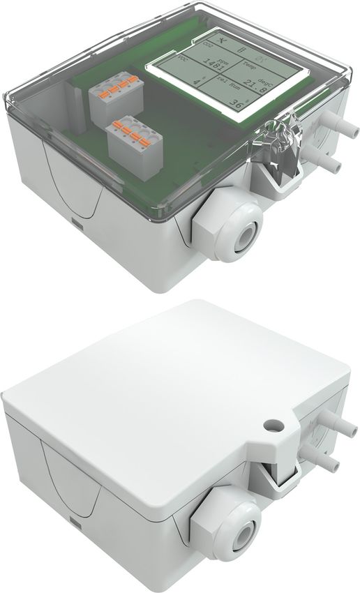
» DPA+ (LCD) RS485 Modbus
 Differential Pressure Transmitter

 Datasheet
 Subject to technical alteration
 Issue date: 23.10.2020 • A111

 » APPLICATION
 Differential pressure and volume flow transducer for monitoring differential pressure and volume flow of air and other non-flammable and non-
 aggressive gases. Three types with eight different measuring ranges are available for different applications. In addition to differential pressure all
 variants provide the calculated volume flow as second analog output signal. LCD models with RGB background light have a transparent cover.
 Display configuration, k-values for flow calculation (default 1500) and threshold values for color changes can be parameterized via Thermokon
 USEapp. The mounting base (included in delivery) allows mounting on a level surface or mounting on DIN rail TS35 (35x7,5 mm) according to EN
 60715.

 » TYPES AVAILABLE
 Differential pressure and volume flow transducer with display – RS485 Modbus
 DPA250+ (LCD) RS485 Modbus MultiRange
 DPA2500+ (LCD) RS485 Modbus MultiRange
 DPA7000+ (LCD) RS485 Modbus MultiRange
 Differential pressure and volume flow transducer with 2 digital inputs, optional with display– RS485 Modbus
 DPA250+ (LCD) RS485 Modbus MultiRange 2IN
 DPA2500+ (LCD) RS485 Modbus MultiRange 2IN
 DPA7000+ (LCD) RS485 Modbus MultiRange 2IN
 MultiRange: Measuring ranges adjustable at the transducer | : automatic zero-point calibration (optional)

 » NOTES ON DISPOSAL
 As a component of a large-scale fixed installation, Thermokon products are intended to be used permanently as part of a building
 or a structure at a pre-defined and dedicated location, hence the Waste Electrical and Electronic Act (WEEE) is not applicable.
 However, most of the products may contain valuable materials that should be recycled and not disposed of as domestic waste.
 Please note the relevant regulations for local disposal.

 » PRODUCT TESTING AND CERTIFICATION
 Declaration of conformity

 The declaration of conformity of the products can be found on our website https://www.thermokon.de/.

Thermokon Sensortechnik GmbH, Platanenweg 1, 35756 Mittenaar, Germany · tel: +49 2778 6960-0 fax: -400 www.thermokon.com· email@thermokon.com
 DPA+_(LCD)_RS485_Modbus_Datasheet_en.docx © 2020
Page 2 / 8 Issue date: 23.10.2020

 » SECURITY ADVICE – CAUTION
 The installation and assembly of electrical equipment should only be performed by authorized personnel.
 The product should only be used for the intended application. Unauthorised modifications are prohibited! The product must not be
 used in relation with any equipment that in case of a failure may threaten, directly or indirectly, human health or life or result in
 danger to human beings, animals or assets. Ensure all power is disconnected before installing. Do not connect to live/operating
 equipment.
 Please comply with
 • Local laws, health & safety regulations, technical standards and regulations
 • Condition of the device at the time of installation, to ensure safe installation
 • This data sheet and installation manual

 » USE ENCLOSURE WITH UV AND WEATHER RESISTANCE
 Outdoor plastic enclosures age over time, fade or form microcracks on the surface. USE housings are therefore made of white polycarbonate (PC)
 with titanium dioxide and the lightest stable additives. Due to the reflection of the entire light spectrum including the UV component, the titanium
 dioxide effectively counteracts the photochemical degradation of polymer, whereby the colors remain saturated longer. The material is also resistant
 to cold and frost.

 » TECHNICAL DATA
 Measuring values differential pressure, volume flow

 Medium air or other non-flammable/non-aggressive gases

 Output voltage 0..10 V or 0..5 V, min. load 10 kΩ
 (live-zero configuration via Thermokon USEapp)

 Network technology RS485 Modbus, RTU, half-duplex, baud rate 9.600, 19.200, 38.400 or 57600, parity: none (2 stopbits),
 even or odd (1 stopbit)

 Power supply 15..35 V = or 19..29 V ~ SELV

 Power consumption max. 2,3 W (24 V =) | max. 4,3 VA (24 V ~)

 Measuring range velocity 0… 750.000 m³/h (default), optionally configured via Thermokon USEapp

 Measuring range pressure type 250 type 2500 type 7000
 *selectable at the device 0..+25 | 0..+50 | 0..+100 | -100..+100 | 0..+100 | 0..+250 | 0..+1000 | 0..+1500 | 0..+2000 |
 0..+250 | -25..+25 | -50..+50 | - 0..+500 | 0..+1000 | 0..+1500 | 0..+2500 | 0..+3000 | 0..+4000 |
 100..+100 | -150..+150 Pa 0..+2000 | 0..+2500 Pa 0..+5000 | 0..+7000 Pa

 Accuracy pressure ±1 Pa at range
Issue date: 23.10.2020 Page 3 / 8

 » MOUNTING ADVICES
 Before installing the device, please check the leak tightness of the pressure lines. A prerequisite for the operation is a proper installation of all
 electrical supply, control and sensing leads as well as the pressurized connection line.

 • In order to connect the device, the process lines must be unpressurized
 • Consider the suitability of the device for the medium to be measured
 • Consider maximum pressures

 » DIFFERENTIAL PRESSURE IN HVAC SYSTEMS

 Overpressure FAN Filter

Thermokon Sensortechnik GmbH, Platanenweg 1, 35756 Mittenaar, Germany · tel: +49 2778 6960-0 fax: -400 www.thermokon.com· email@thermokon.com
 DPA+_(LCD)_RS485_Modbus_Datasheet_en.docx © 2020
Page 4 / 8 Issue date: 23.10.2020

 » CONNECTION PLAN
 DPA+ (LCD) RS485 Modbus

 ◄ A+ A+ RS485 cable is looped through, connect both cable shields using the enclosed
 B-
 ► A+ 2-pol. Connect terminal as shown.
 ◄ B- A+
 ► B- B-

 ► volume flow | 0..10 V
 ► differential pressure | 0..10 V
 ◄ GND
 ◄ 15..35 V ⎓ / 19..29 V ∿

 DPA+ (LCD) RS485 Modbus 2IN

 ◄ A+ A+ RS485 cable is looped through, connect both cable shields using the enclosed
 B-
 ► A+ 2-pol. Connect terminal as shown.
 ◄ B- A+
 ► B- B-

 ► volume flow | 0..10 V
 ► differential pressure | 0..10 V
 ◄ GND
 ◄ 15..35 V ⎓ / 19..29 V ∿

 ◄ IN2
 ► IN2
 ◄ IN1
 ► IN1

Thermokon Sensortechnik GmbH, Platanenweg 1, 35756 Mittenaar, Germany · tel: +49 2778 6960-0 fax: -400 www.thermokon.com· email@thermokon.com
 DPA+_(LCD)_RS485_Modbus_Datasheet_en.docx © 2020
Issue date: 23.10.2020 Page 5 / 8

 Measuring range adjustment – type 250 | 2500 | 7000

 default
 Response time Output voltage Unit

 default default default

 Dip switches, plug-in card

 Address

 ON=20 (1) ON=21 (2) ON=22 (4) ON=23 (8) ON=24 (16)
 default

 Termination 120Ω Baud rate Parity

 deactivated activated 9600 19200 38400 57600 None Even Odd
 default default default

 Flow calculation: (default parameters)
 ∆
 = ∗ �2 ∗ with k=1500, fan manufacturer Rosenberg, Comefri, Nicotra Gebhardt, default measuring range 0..750.000 m³/h. Further

 calculation formulas, fan manufacturers and k-values can be selected via the USEapp.

 Rosenberg ∙ Comefri ∙Gebhardt ∙Nicotra Ziehl-Abegg ∙EBM-Papst Fläkt Woods

 ∆ 1
 = ∗ �2 ∗ = ∗ �∆ = ∗ �∆

Thermokon Sensortechnik GmbH, Platanenweg 1, 35756 Mittenaar, Germany · tel: +49 2778 6960-0 fax: -400 www.thermokon.com· email@thermokon.com
 DPA+_(LCD)_RS485_Modbus_Datasheet_en.docx © 2020
Page 6 / 8 Issue date: 23.10.2020

 Register 400 = 1 (Unit SI)
 Address Access Description Resolution / Unit
 8 R / s16 Differential pressure 1 SI 1.0 Pa
 Volumetric flow 1 (16 Bit) (if register address 404 is set to the value 2, the SI 100.0 m³/h
 9 R / u16 value scales the unit m³/s) m³/s

 50 Volumetric flow 1 (32 Bit) (if register address 404 is set to the value 2, the SI 1.0 m³/h
 Low value scales the unit m³/s) m³/s
 R / u32
 51
 High This register is available since firmware V1.6 (see register 505)

 Register 400 = 2 (Unit Imperial)
 Address Access Description Resolution / Unit
 8 R / s16 Differential pressure 1 Imperial 0.001 inWC
 Volumetric flow 1 (16 Bit) (if register address 404 is set to the value 2, the Imperial 10.0 cfm
 9 R / u16 value scales the unit m³/s)

 50 Volumetric flow 1 (32 Bit) (if register address 404 is set to the value 2, the Imperial 1.0 cfm
 Low value scales the unit m³/s)
 R / u32
 51
 High This register is available since firmware V1.6 (see register 505)

 Optional (IN1 | IN2)
 NTC10k temperature sensors or floating contacts can be connected to the inputs (IN1 & IN2).
 Address Access Description Values
 92 R / s16 Input 1 – Switch contact 0 Contact open

 93 R / s16 Input 2 – Switch contact 1 Contact closed

 Register 400 = 1 (Unit SI)
 Address Access Description Resolution / Unit
 Input 1 - Temperature NTC10k SI 0.1 °C
 90 R / s16
 (beta value configurable, register address 490, default: 3864)

 Input 2 - Temperature NTC10k SI 0.1 °C
 91 R / s16
 (beta value configurable, register address 491, default: 3864)

 Register 400 = 2 (Unit Imperial)
 Address Access Description Resolution / Unit
 Input 1 - Temperature NTC10k Imperial 0.1 °F
 90 R / s16
 (beta value configurable, register address 490, default: 3864)

 Input 2 - Temperature NTC10k Imperial 0.1 °F
 91 R / s16
 (beta value configurable, register address 491, default: 3864)

 The modbus address of the device is set in the range of 1 ... 31 (binary encoded) using a 5-pole DIP switch. With address 0 via DIP, an extended
 address range (32..247) is available via USEapp.
 Modbus addresses:
 USE-RS485 Modbus Interface
 A detailed description of the Modbus addresses can be found under the following link:
 → Download

Thermokon Sensortechnik GmbH, Platanenweg 1, 35756 Mittenaar, Germany · tel: +49 2778 6960-0 fax: -400 www.thermokon.com· email@thermokon.com
 DPA+_(LCD)_RS485_Modbus_Datasheet_en.docx © 2020
Issue date: 23.10.2020 Page 7 / 8

 » AUTOMATIC ZERO-POINT CORRECTION - (OPTIONAL)
 Transmitters equipped with the auto-zero correction are maintenance free.

 The auto-zero correction electronically adjusts the transmitter zero every 10 minutes. The function eliminates all output signal drift
 due to thermal, electronic or mechanical effects. The auto-zero correction takes approx. 4 seconds after which the device returns
 to its normal measuring mode. During the 4 second correction period, the output and display values will freeze to the latest
 measured value.

 » MANUAL ZERO-POINT CORRECTION (FOR DEVICES WITHOUT AUTO-ZERO FUNCTION)
 In normal operation zero point correction should be executed every 12 months.
 Attention! For executing zero point correction the power supply must be connected one hour
 before.
 • Release both connection tubes from the pressure terminals + and -
 • Press the button until the LED lights permanently
 • Wait until the LED flashes again and reinstall the connection tubes to the pressure ports (note +
 and -)

 » CONFIGURATION
 The Thermokon bluetooth dongle with micro-USB is required for communication between USEapp and
 USE-M / USE L (Item No..: 668262). Commercial bluetooth dongles are not compatible.
 Application-specific reconfiguration of the devices can be carried out using the Thermokon USEapp. The
 configuration is carried out in the voltage-supplied state.
 The configuration-app and the app description can be found in the Google Play Store or in the Apple App
 Store.

 » DIMENSIONS (MM)

Thermokon Sensortechnik GmbH, Platanenweg 1, 35756 Mittenaar, Germany · tel: +49 2778 6960-0 fax: -400 www.thermokon.com· email@thermokon.com
 DPA+_(LCD)_RS485_Modbus_Datasheet_en.docx © 2020
Page 8 / 8 Issue date: 23.10.2020

 » ACCESSORIES (INCLUDED IN DELIVERY)
 Mounting base enclosure USE-L Item No. 668361
 2 m PVC connection tube Item No. 484268
 KKS40 kit Item No. 430135
 • 2 plastic duct flanges • 4 mounting screws 4x20

 Mounting kit universal Item No. 698511
 • Cover screw + screw cover• 2 Rawlplugs • 2 Screws (countersunk head) • 2 Screws (rounded head)

 » ACCESSORIES (OPTIONAL)
 Bluetooth dongle USE for USEapp Item No. 668262
 Converter RS485 Modbus-USB incl. driver CD Item No. 668293
 T-hose connector for pressure hoses Ø=4 mm (10 pcs) Item No. 668323
 Adapter 90° angle for pressure hoses Ø=4 mm Item No. 668330
 Metal duct connectors 40 mm Item No. 265138
 Metal duct connectors 100 mm Item No. 302531

Thermokon Sensortechnik GmbH, Platanenweg 1, 35756 Mittenaar, Germany · tel: +49 2778 6960-0 fax: -400 www.thermokon.com· email@thermokon.com
 DPA+_(LCD)_RS485_Modbus_Datasheet_en.docx © 2020
You can also read