Copper Rays Solar Project - U.S. Bureau of Land Management Southern Nevada District Field Office
←
→
Page content transcription
If your browser does not render page correctly, please read the page content below
Plan o f D e v e l o p m e n t

Copper Rays Solar Project

                                Prepared for

U.S. Bureau of Land Management
    Southern Nevada District Field Office
                           Las Vegas, NV
                                 Prepared by

                       Copper Rays Solar, LLC

                                   June 2021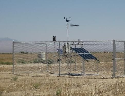
Contents

Section                                                                                                                                     Page
Project Overview and Purpose and Need ......................................................................................... 1-1
   1.1 Introduction ............................................................................................................................ 1-1
        1.1.1 Type of Facility, Planned Uses, Generation Output ...................................................... 1-1
        1.1.2 Applicant’s Schedule for the Project ............................................................................. 1-1
   1.2 Proponent’s Purpose and Need for the Project...................................................................... 1-2
        1.2.1 Need for Renewable Energy.......................................................................................... 1-2
        1.2.2 Project Purpose and Need..................................................Error! Bookmark not defined.
        1.2.3 Power Market and Project Benefits .............................................................................. 1-4
Right-of-Way Location ....................................................................................................................... 2-1
   2.1 Project Location, Land Ownership, and Jurisdiction............................................................... 2-1
       2.1.1 Legal Land Description .................................................................................................. 2-1
Project Facilities and Design.............................................................................................................. 3-1
   3.1 Power Plant Facilities, Photovoltaic Conversion Process ....................................................... 3-1
       3.1.1 Power Plant Facilities .................................................................................................... 3-1
       3.1.2 Numbers and Dimensions of Solar Array and Other Equipment .................................. 3-2
       3.1.3 Temporary Construction Workspace, Yards, Staging Areas.......................................... 3-3
       3.1.4 Geotechnical Studies and Data Needs .......................................................................... 3-4
       3.1.5 Water............................................................................................................................. 3-5
       3.1.6 Ancillary Facilities .......................................................................................................... 3-5
       3.1.7 Site Security................................................................................................................... 3-8
       3.1.8 Electrical Components, New Equipment, and Upgrades .............................................. 3-8
       3.1.9 Interconnection to the Electrical Grid........................................................................... 3-9
       3.1.10 Erosion Control and Stormwater Management .......................................................... 3-9
       3.1.11 Vegetation Treatment and Weed Management......................................................... 3-9
       3.1.12 Waste and Hazardous Materials Management......................................................... 3-10
       3.1.13 Fire Protection........................................................................................................... 3-11
       3.1.14 Health and Safety Program ....................................................................................... 3-11
   3.2 Alternatives Considered........................................................................................................ 3-12
   3.3 Other Federal, State, and Local Permits and Approvals ....................................................... 3-13
   3.4 Financial and Technical Capability of the Applicant ............................................................. 3-15
Construction of Project Facilities....................................................................................................... 4-1
   4.1 Construction Schedule and Sequence .................................................................................... 4-1
   4.2 Design, Layout, and Installation.............................................................................................. 4-2
   4.3 Approach to Phased Construction and Operations ................................................................ 4-4
   4.4 Access and Transportation System, Component Delivery, Worker Access ............................ 4-5
   4.5 Construction Workforce Numbers, Vehicles, Equipment, Timeframes.................................. 4-5
   4.6 Site Preparation ...................................................................................................................... 4-6
   4.7 Solar Array Assembly and Construction.................................................................................. 4-7
   4.8 Construction Waste Management.......................................................................................... 4-7
       4.8.1 Wastewater ................................................................................................................... 4-8
                                                                                                                                   CONTENTS

                                                                                                                                                   i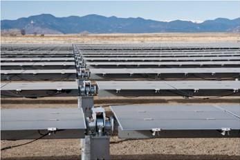
4.9 Gravel, Aggregate, and Concrete Needs and Sources............................................................ 4-8
     4.10 Electrical Construction Activities.......................................................................................... 4-8
         4.10.1 34.5kV Collection System............................................................................................ 4-8
         4.10.2 230kV Transmission Line............................................................................................. 4-9
         4.10.3 Standard Transmission Line Construction Techniques ............................................... 4-9
     4.11 Aviation Lighting................................................................................................................. 4-11
     4.12 Site Stabilization, Protection, and Reclamation Practices.................................................. 4-11
         4.12.1 Erosion and Sediment Control Measures ................................................................. 4-11
         4.12.2 Dust Control.............................................................................................................. 4-12
     4.13 Construction Water Usage ................................................................................................. 4-12
     4.14 Rehabilitation and Decommissioning................................................................................. 4-12
         4.14.1 Site Stabilization, Protection, and Reclamation........................................................ 4-12
         4.14.2 Decommissioning...................................................................................................... 4-12
Related Facilities and Systems.......................................................................................................... 5-1
   5.1 Transmission System Interconnect ........................................................................................ 5-1
       5.1.1 Proposed Transmission System .................................................................................... 5-1
       5.1.2 Ancillary Facilities.......................................................................................................... 5-1
       5.1.3 Status of Power Purchase Agreements......................................................................... 5-1
       5.1.4 Status of Interconnect Agreement ............................................................................... 5-1
       5.1.5 General Design and Construction Standards ................................................................ 5-1
   5.2 Gas Supply Systems ................................................................................................................ 5-1
   5.3 Other Related Systems ........................................................................................................... 5-2
       5.3.1 Communication System Requirements during Construction and Operation ............... 5-2
       5.3.2 Project Access Road ...................................................................................................... 5-2
Operation and Maintenance............................................................................................................. 6-1
  6.1 Operations Workforce and Equipment .................................................................................. 6-1
  6.2 Operation and Maintenance Needs ....................................................................................... 6-1
       6.2.1 Periodic Maintenance................................................................................................... 6-1
Environmental Considerations ......................................................................................................... 7-1
   7.1 General Description of Site Characteristics and Potential Environmental Issues .................. 7-1
       7.1.1 Recreation..................................................................................................................... 7-1
       7.1.2 Soil Resources ............................................................................................................... 7-1
       7.1.3 Water Resources........................................................................................................... 7-1
       7.1.4 Biological Resources and Special Status Species .......................................................... 7-2
       7.1.5 Visual Resources ........................................................................................................... 7-3
       7.1.6 Cultural Resources and Native American Concerns...................................................... 7-3
       7.1.7 BLM Herd Management Areas...................................................................................... 7-3
   7.2 Applicant Proposed Measures................................................................................................ 7-3
References ......................................................................................................................................... 8-1

                                                                                                                                                           i
CONTENTS
Tables
1-1 Project Schedule Overview
2-1 Township/Range and Section Information
3-1 Project-Related Roads
3-2 Wastes Potentially Generated by the Project
3-3 Hazardous Materials that May Be Used During Operation
3-4 Federal, State, and Local Permits and Authorizations That May Be Required for the Project
4-1 Project Construction Schedule Major Milestones
6-1 Routine Maintenance Protocol
Figures – End of Document
1-1 Site Vicinity Map
1-2 Preliminary Site Map
1-3 Preliminary Gen-Tie Plan
1-4 O&M, Move-On, Energy Storage System, and Onsite Substation Layout
1-5 Collection Line Direct Buried & Trench Details
1-6 Typical Gen-Tie & Collection Line Poles
1-7 Preliminary Substation Plan
1-8 Preliminary Substation Section
Appendix A – Legal Land Description
Appendix B- Master Title Plat
iiiSECTION 1
Project Overview and Purpose and Need
1.1 Introduction
1.1.1 Type of Facility, Planned Uses, Generation Output
Copper Rays Solar, LLC, a subsidiary of Leeward Renewable Energy (Leeward) proposes to construct,
own, and operate the Copper Rays Solar Project (Project), consisting of up to a nominal 700-
megawatt (MW) alternating current (AC) solar photovoltaic (PV) power generating facility with
battery storage on approximately 5,127 acres of Bureau of Land Management (BLM) administered
land located in Nye County, Nevada (Figure 1-1). The Project consists of three phases, referred to as
Copper Rays 1 (200MW), Copper Rays 2 (250MW), and Copper Rays 3 (250MW). The power
produced by the Project would be conveyed to GridLiance West’s (GLW) bulk transmission system
via a generation-tie transmission line (gen-tie line), which would interconnect to GLW’s Gamebird
Substation located north of the Project site and southeast of Pahrump, Nevada. The interconnection
will allow all California Independent System Operator (CAISO) participants to purchase renewable
energy generated by the Project under a long-term Power Purchase Agreement (PPA) to deliver
energy from a (nominal) 700MW size generating facility.
This Plan of Development (POD) is being submitted to the BLM’s Renewable Energy Coordination
Office that is part of the Southern Nevada District Field Office in connection with an SF 299 right-of-
way (ROW) application for the development of a commercial solar PV generating station, with a
combined generation output rating of approximately 700MW. This POD describes the design,
location, and proposed permitting and construction schedule for the Project. It has been prepared in
accordance with the December 19, 2012 Solar Energy Plan of Development Outline issued by the
BLM (BLM 2012a). The Project will be constructed using photovoltaic modules mounted on
horizontal tracker structures supported by steel posts driven into the ground. Steel table frames
(tabletops) are bolted to the tracker structures and PV modules are mechanically fastened to the
tables. The tracking units are arranged into north to south-oriented rows, and are powered by a
drive motor to track the east-west path of the sun on a single axis throughout the day. In the event
that the results of detailed geotechnical investigations indicate driven steel posts are not an optimal
foundation, other embedded foundation designs including concrete footings may be utilized.
Concrete foundations will be required for other Project components, including power conversion
stations (PCS) (which house the inverters), PV combining switchgear (PVCS) and transformers,
weather stations, and substation equipment.
1.1.2 Applicant’s Schedule for the Project
Construction of the Project, from site preparation and grading to commercial operation, is expected
to begin as early as January 2024. The Applicant proposes to construct the Project in three phases
(i.e., Copper Rays 1, Copper Rays 2, and Copper Rays 3). Copper Rays 1 would consist of 200MW on
approximately 1,000 acres in the northeastern most portion of Project site. Copper Rays 2 would
consist of 250MW on approximately 2,000 acres south of and adjacent to Copper Rays 1. Copper
1-1Rays 3 would consist of 250MW on approximately 2,000 acres south of and adjacent to Copper Rays
2. Figure 1-2 depicts a preliminary site plan with Project phases identified.
Construction of the entire Project (all phases) is expected to take approximately 72 months to
complete. A project schedule is provided in Table 1-1. Construction will include the major phases of
mobilization, construction grading and site preparation, installation of drainage and erosion
controls, PV panel/tracker assembly, and solar field construction. Project development will include
both permitting and construction, as shown in Table 1-1. The sequencing of construction activities
are described as part of the construction description sections that follow.
TABLE 1-1
Project Schedule Overview
Activity Duration Estimated Completion Dates
Complete POD 3 months May 2021
Prepare required NEPA documents (including NOI) 24 months July 2022
Other Permits and Approvals 9 months Sept 2023
Pre-construction biological clearances 3 months Sept 2023
Project construction 72 months Jan 2024
Total elapsed time 68 to 80 months
1.2 Proponent’s Purpose and Need for the Project
1.2.1 Need for Renewable Energy
The United States has a greater solar energy resource potential than any other industrialized nation.
The multiple benefits associated with developing this resource have been recognized repeatedly by
both federal and state policy-makers. Development of solar resources reduces reliance on foreign
sources of fuel, promotes national security, diversifies energy portfolios and contributes to the
reduction of greenhouse gas emissions. The demand for power continues to grow in the Western
United States. As older technology fossil-fuel plants reach the end of their useful lives, there is a
need to replace them with clean, reliable resources. Recognizing this need, many Western states,
including Nevada, have enacted legislation to encourage or mandate the development of renewable
generation.
Senate Bill (SB) 1078 established California’s Renewables Portfolio Standard (RPS) program in 2002.
The RPS program requires electrical corporations and electric service providers to purchase a
specified minimum percentage of electricity generated by eligible renewable energy resources. The
bill requires the California Energy Commission to certify eligible renewable energy resources, to
design and implement an accounting system to verify compliance with the RPS by retail sellers, and
to allocate and award supplemental energy payments to cover above-market costs of renewable
energy. Under SB 1078, each electrical corporation was required to increase its total procurement of
eligible renewable energy resources by at least one percent per year so that 20 percent of its retail
sales were procured from eligible renewable energy resources.
1-2In 2006, SB 107 accelerated the RPS program by establishing a deadline of December 31, 2010, for
achieving the goal of having 20 percent of total electricity sold to retail customers in California per
year generated from eligible renewable energy resources. The RPS goal was increased to 33 percent
when Governor Schwarzenegger signed Executive Order S-14-08 in November 2008. Executive Order
S-14-08 was later superseded by Executive Order S-21-09 on September 15, 2009. In 2011 SB 1X-2
increased the statutory RPS to 33 percent and expanded the RPS program to include customer-
owned utilities. In addition, SB 1X-2 limits the use of out-of-state tradable renewable energy
certificates to 25 percent in 2013, 15 percent in 2016, and 10 percent thereafter. On October 07,
2015, Governor Brown signed the Clean Energy and Pollution Act of 2015 or SB 350 that increased
the RPS goal from 33 percent to 50 percent by 2030. The legislation also required local publicly
owned electric utilities to establish annual targets for energy efficiency savings and demand
reduction consistent with this goal.
Over the next several decades, Southern Nevada will be a critical location for the development of
utility-scale solar generating capacity. The Obama administration’s Clean Power Plan rule requiring
coal retirement, California’s and Nevada’s RPS legislation, and reasonably foreseeable demands
large energy users in Nevada will combine over the next decade to drive market conditions and
place additional demands on federally managed lands in the Western U.S. In addition, the CAISO and
other jurisdictions have undertaken initial steps to regionalize the ISO for the Western States; such
regionalization over the next 5-10 years could significantly increase Nevada’s potential to address
solar development needs and to reduce greenhouse gas emissions in the Western region. By way of
example only, assuming California’s 50% RPS legislation creates a need for an additional 30 gigawatt
(GW) of additional solar PV resources between 2016 and 2030, it would be appropriate to identify
and set aside 500,000 acres of land to build out solar projects to meet this demand. The Copper
Rays Solar Project will aid in meeting this demand.
Additionally, the federal government has enacted legislation strongly encouraging the development
of renewable energy. As part of an overall strategy to develop a diverse portfolio of domestic energy
supplies for our future, the National Energy Policy of 2001 and the Energy Policy Act of 2005 (Public
Law 109-58, August 8, 2005) encourage the development of renewable energy resources, which
includes solar energy. Section 211 of the Energy Policy Act of 2005 encourages the approval of at
least 10,000MW of non-hydropower renewable energy production on the public lands within the
next 10 years. In early 2009, Secretary of the Interior Salazar issued Orders 3283 and 3285, making
the production, development, and delivery of renewable energy top priorities for the Department of
the Interior. Congress is also considering legislation that would implement greenhouse gas
emissions requirements and/or national renewable portfolio standards.
Part of the government’s efforts to promote renewable energy depend on the ultimate
development of increasingly economical facilities that drive down the price of renewable energy,
and ultimately enable it to compete in the market place with fossil fuel facilities.
The fundamental purpose of the Copper Rays Solar Project is to construct a clean, renewable source
of solar electricity that helps meet the region’s growing demand for power and helps fulfill national
and state renewable energy and greenhouse gas emission goals. Solar energy provides a sustainable,
renewable source of power that helps reduce fossil fuel dependence and greenhouse gas emissions.
Considering the entire process, from raw material sourcing through end-of-life-cycle collection and
recycling, the Project’s combined 700MW of additional generating capacity will produce a small
fraction of the greenhouse gas emissions of a similar capacity fossil fuel plant.
Specific Project objectives are:
1-3• Establish a solar PV power-generating facility that is of sufficient size and configuration to
produce at least 700MW of electricity in order to assist the States of Nevada and California in
achieving their RPS by providing a significant new source of renewable energy.
• Produce and transmit electricity at a competitive cost.
• Locate the facility in Nye County in proximity to an available connection to the existing
electrical distribution infrastructure.
• Minimize environmental effects by:
o Using existing electrical distribution facilities, rights-of-way, roads and other existing
infrastructure where practicable;
o Minimizing water use during operation; and
o Reducing greenhouse gas emissions.
• Use solar technology that is available, proven, efficient, and easily maintained, recyclable,
and environmentally sound.
1.2.2 Power Market and Project Benefits
The Project will interconnect to GLW’s transmission system via an approximately 4-mile gen-tie to
the Gamebird Substation, located north of the Project site and southeast of Pahrump, Nevada. The
electrical output from the Project will be sold to one or more utility companies to support their
compliance with Nevada's or California’s renewable portfolio standard or other green energy
initiatives. The interconnection will allow all CAISO participants to purchase renewable energy
generated by the Project under a long-term Power Purchase Agreement (PPA) to deliver energy
from a (nominal) 700MW size generating facility.
The Project is well suited to arid environments because of the technology’s low water consumption.
This is a key consideration in Southern Nevada and the Western U.S., as the population grows and
water supplies become more constrained. PV solar technology, which converts sunlight directly into
electrical energy, entails no thermal process, and therefore does not require process or cooling
water to produce electricity. Water consumption during operations will consist exclusively of dust
control, panel washing and domestic use for on-site personnel and is between 95 and 99 percent
less that of concentrating solar projects that employ conventional steam turbines to generate
electricity.
The Project will also create family-wage jobs for Southern Nevada. The Southern Nevada economy
has been adversely affected by the turndown in the economy and, in particular, by the loss of
construction jobs. The Project is anticipated to create an average of 500-700 construction jobs with
a peak not anticipated to exceed 1000 jobs at any given time, and create up to 10 long-term full-
time-equivalent (FTE) operational jobs. These jobs will in turn support many other jobs in the
Southern Nevada economy.
1-4SECTION 2
Right-of-Way Location
2.1 Project Location, Land Ownership, and Jurisdiction
The Project area is comprised of approximately 5,127 acres of public lands administered by the BLM
in an unincorporated area of Nye County, Nevada. The Project would be located immediately west
of State Route 160 (SR-160) and approximately 8 miles southeast of the town of Pahrump, Nevada
(Figure 1-1).
2.1.1 Legal Land Description
The Project site is located in T21S, R54E and T22S, R54E, excluding the generation-tie line. The
township/range and section information for the primary components of the Project is shown in
Table 2-1. Township/range and section information relative to components of the Project is also
depicted on Figure 1-2. A complete legal description can be found in Appendix A.
TABLE 2-1
Township/Range and Section Information
Facility Township/Range Section
Project Boundary 21S/54E 14,13,23,24,26,25,35,36
22S/55E 1,2
Solar Field and Ancillary Facilities 21S/54E 23,24,25,26,35,36
22S/54E 1,2
Temporary Staging Area, O&M Area and Onsite 21S/54E 2,13,14,23,24,26
Substation
Project Access Road 21S/55E 18
Generation-Tie Line to GLW’s Gamebird Substation 20S/54E 34,35
21S/54E 1,2,12,13
2-1SECTION 3
Project Facilities and Design
3.1 Power Plant Facilities, Photovoltaic Conversion Process
3.1.1 Power Plant Facilities
The Project will include the following main elements:
• PV solar array field and associated interior access ways and perimeter road.
• Single-axis, horizontal tracker systems (including tilt brackets and tabletops) supported by driven
steel posts or other embedded foundation design.
• PV solar modules.
• Direct current (DC) collection system comprised of underground DC cabling and combiner boxes.
• Meteorological stations.
• Power conversion stations (PCSs), which include the DC to alternating current (AC) inverters and
the medium voltage transformers which steps up the voltage to 34.5 kilovolts (kV). The PCS will
also include emergency backup power for the tracker system in the event of high winds and loss
of grid power.
• An underground and/or overhead 34.5kV collection system to convey electricity from the solar
field to the onsite substation.
• A fully fenced substation with 34.5kV to 230kV step-up transformers, breakers, buswork,
protective relaying and associated substation equipment. The onsite substation also may include
a microwave tower, a control house, mechanical electrical equipment room(s) and one or more
transformers.
• Energy storage system (ESS) consist of self-contained battery storage modules placed in racks,
converters, switchboards, inverters, transformers, controls, and integrated heating, ventilation,
and air conditioning (HVAC) units, all enclosed in one or more buildings or in prefabricated metal
containers.
• An onsite connection to the Gamebird Substation via an approximate 4-mile gen-tie line.
• The Project may include an approximately operation and maintenance (O&M) area that will
accommodate as necessary an O&M building, parking area, and other associated facilities such
as above ground water storage tanks, septic system, security gate, signage, and flagpoles.
• The Project may transport water by either truck or pipeline to provide construction water, fire
protection water, and other operational water supply requirements. Pipeline locations, if
utilized, would be located within the ROW application area and exact locations to be
determined with further analysis.
• A fire break around the exterior of the perimeter fence.
3-1• Graveled access road.
• Site security facilities including perimeter security fencing-controlled access gates, and signage.
• Perimeter desert tortoise exclusion fencing, as determined necessary.
• Fiber optic cable installation for communications to the Project will be installed underground or
on overhead lines along the transmission line corridor between the onsite substation and the
point of interconnection with GLW systems.
Construction of the Project will require the following temporary facilities to be located within the
permanent ROW application area. These temporary facilities will be removed at the end of the
construction period.
• Temporary construction mobilization and laydown area(s). These will contain temporary
construction trailers, construction workforce parking, above ground water tanks, materials
receiving and materials storage.
• Temporary construction utilities that may include temporary power connection to the VEA
distribution system adjacent to the Project, temporary power generator, and temporary above-
ground water line.
The following sections describe the Project site arrangement and the processes, systems, and
equipment that constitute the power plant.
3.1.1.1 Energy Conversion Equipment
As a solar PV facility, the Project relies on sunlight as its sole source of fuel. All of the electricity
generated by the Project will be generated through the conversion of solar energy to electricity by
the PV modules. The Project will not consume fossil fuels of any type for power generation.
The design calls for PV modules, inverters, and transformers to be combined into arrays that are
repeated to reach the full contract capacity. The inverter and transformer sizes will be selected
based on the cost and market availability of these units.
During operational daylight hours, the Project will generate its own power for equipment operation.
During non-daylight hours, the Project will require power to keep transformers energized, maintain
communications to Project equipment, and provide power for heating, ventilation, and air conditioning
and lighting to the O&M building. The Project will enter into a retail service agreement with the local
retail power provider to purchase power during non-daylight hours.
3.1.2 Numbers and Dimensions of Solar Array and Other Equipment
The Project will be constructed using photovoltaic modules mounted on single-axis, horizontal tracker
systems. The design layout calls for PV modules, inverters, and transformers to be combined into
arrays that are repeated to reach the full contract capacity (See Figure 1-2). The primary Project
components include solar arrays, transmission lines, onsite substation, site entrance, and O&M
facilities. Power from multiple rows of PV modules will be collected through a system of combiner
boxes to a PCS, inverters for conversion of power from DC to AC, transformers, and collection lines
and delivered to the Project substation.
3.1.2.1 Horizontal Trackers
PV modules on horizontal trackers are mounted horizontally and are not tilted to the south. A
typical array layout using horizontal trackers is shown in below. The tracker units are arranged in
3-2north-south oriented rows and drive motors rotate
the solar panels from east to west to follow the sun
(on a single axis) throughout the day.
The vertical support legs for the trackers consist of
foundations that may include: (1) concrete piers or
(2) driven posts. The preferred mounting
configuration utilizes directly embedded driven
posts and concrete piers will only be utilized if
subsurface conditions do not support driven posts.
Each tracker unit has motors and actuator are
mounted to one of the driven posts and do not Typical Tracker Array Configuration
require separate foundations for mounting. and Mounting Systems
Hydraulic drive systems will not be used. The
motors are only operated for a few seconds every 5-10 minutes during daylight conditions to move
the panels in approximately 1 degree increments. The sound from the tracker motors is less than 70
decibels.
Meteorological stations located at the site will monitor wind speed and communicate with the tracker
units. This allows for the trackers to rotate to a flat position during high wind activity. The
meteorological station towers will be located at multiple locations around the perimeter of the solar
array. Meteorological station towers will be monopole or lattice design.
Each PCS Shelter is equipped with communication equipment to wirelessly communicate with the
tracker units to control operation and detect anomalous conditions. The PCS Shelter is also
equipped with emergency backup power required to rotate the tracker units to their stow position
in the unlikely event of high winds and a loss of the primary electrical connection from the Project to
GLW’s transmission system.
3.1.2.2 Emergency Backup Power
The emergency back-up power requirement would be met by utilizing a small battery-based
uninterruptible power supply (UPS) with each PCS shelter. Batteries would be lead acid based
and/or lithium ion. Inspections would be performed to ensure ambient temperature requirements
are met and visual inspections of all batteries as part of the preventative maintenance program.
3.1.3 Temporary Construction Workspace, Yards, Staging Areas
The Project construction contractor will develop a temporary construction mobilization and laydown
area to build the Project. The construction mobilization and laydown area will include the following
facilities:
• Mobile trailer construction offices
• Temporary water service and fire water supply holding tanks
• Temporary construction power and water service
• Portable toilets
• Parking for construction worker’s vehicles
• Tool sheds/containers
• Laydown area for construction equipment and material delivery
These areas will provide laydown for installation of solar equipment in the immediate vicinity of panel
installation. Construction of the 230kV transmission line at the site will require temporary construction
3-3areas at each tower location and at locations required for conductor stringing and pulling operations.
These areas will be required for staging equipment and materials for foundation construction and tower
installation. Other temporary laydown areas will be located at the site based on construction
requirements.
Temporary construction power will be provided by a temporary connection to the local VEA
distribution service in the area. A temporary above-ground circuit will be located between the
construction trailer area and the VEA point of interconnection. The temporary construction power
service will be removed (including any towers if required) at the end of the construction period.
Alternatively, generators may be used to provide temporary construction power. All temporary
power and water service lines will be located in within the permanent ROW Project application area.
3.1.4 Geotechnical Studies and Data Needs
3.1.4.1 Geotechnical Studies
To develop a geological profile of the area underlying the Project site, the Applicant will conduct
detailed geotechnical studies prior to construction of the Project to determine the engineering
characteristics of local soils and geology. These geotechnical studies will include:
• Borings up to 25 feet in depth
• Test pits up to 15 feet in depth
• Driving of test posts
Geotechnical and soils analysis will be performed to determine:
1. The presence or absence of rock, old excavation, or fill
2. The classification of the soil strata
3. The bearing capacity of the soil and depth at which footings must be founded
4. Compaction, swelling, collapse and corrosion potential
5. Thermal and electrical resistivity
6. Infiltration
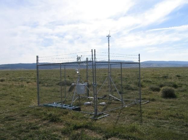
3.1.4.2 Meteorological Stations
The Applicant will install solar meteorological stations (SMSs) at the Project site to gather
information on air temperature, wind direction and speed, and solar transmissivity. It is anticipated
that up to four SMSs will be installed at the site.
The SMSs will consist of either driven post or surface-mounted tri-pods containing meteorological
instrumentation and communication equipment. The maximum height is approximately 10 feet. The
SMS sites will be located within the Project’s perimeter fence; thus they will not be fenced.
Examples of typical SMSs are provided on the following page.
3-4Typical Meteorological Stations
3.1.5 Water
Water will be required during Project construction for construction-related activities, including dust
control. After construction is complete, the Project’s annual water consumption during operation is
expected to be minimal. The Project does not require process water; however, the administrative
area will require domestic potable water service. The main consumption of water during operation
will be for occasional panel washing and/or dust control.
3.1.6 Ancillary Facilities
The following subsections describe the various power plant auxiliary systems associated with the
Project.
3.1.6.1 Supervisory Control and Data Acquisition System
The Project will have a Supervisory Control and Data Acquisition (SCADA) system that will allow for
the remote monitoring and control of inverters and other Project components. The SCADA system
will be able to monitor Project output and availability, and to run diagnostics on the equipment. This
equipment will be located in the O&M building.
The SCADA system will provide control, monitoring, alarm, and data storage functions for the power
plant systems. Redundant capability will be provided for critical SCADA components such that no
single component failure will cause a plant outage. The SCADA will be linked to the inverters, met
stations and relays via fiber optic and copper communications cable. These data links will provide
control, monitoring, alarm, and data storage functions via the control operator interface and control
technician workstation of the SCADA system.
3.1.6.2 Lighting System
The Applicant has incorporated measures designed to reduce night lighting into the Project’s lighting
systems. Night lighting used during construction, operation, and maintenance of the Project will be
controlled or reduced using directed lighting, shielding, and/or reduced lumen intensity. Permanent
lighting will be provided at the O&M building and the main site entrance. The Applicant will prepare
a Lighting Management Plan.
3.1.6.3 Cathodic Protection Systems
While not expected, underground metal structures may have cathodic protection as necessary
based on soil conditions. The only underground metal structures will be the driven posts (to support
3-5the PV modules and combiner boxes) and ground grid used under high voltage equipment to reduce
touch potential. The ground grid will be composed of copper wire and will be limited to the
substation portion of the Project. Cathodic protection is not anticipated at this time, but may be
necessary if the soil corrosivity data from the geotechnical investigation recommends it. Galvanized
metal posts and epoxy-coated rebar may be utilized in lieu of cathodic protection if supported by
soil conditions. If cathodic protection is recommended, a sacrificial anode type cathodic protection
system will be provided. Institute of Electrical and Electronics Engineers (IEEE), Electric Power
Research Institute and the National Association of Corrosion Engineers (NACE) guidelines will be
used in establishing the necessity, type and extent of cathodic protection equipment. All cathodic
protection equipment will be included within the area already designated for the substation.
3.1.6.4 Buildings, Roads, Fencing, and Security
3.1.6.4.1 Buildings
The Project may include an O&M area consisting of a permanent O&M building that would house
administrative, operation, and maintenance equipment and personnel and will have an adjacent
parking area. Additional components of the O&M area include a laydown and storage area, trash
containers, water storage tanks and septic field. The O&M area will be equipped with exterior
lighting as described in the Lighting Management Plan that the Applicant will prepare.
The O&M building will also include communication equipment and a storage and equipment area. It
will contain offices, toilets and other features necessary for habitation on a daily basis. The design
and construction of this building will be consistent with applicable county building standards.
A separate, uninhabited communications enclosure will be located adjacent to the onsite
substation. The communications enclosure will be constructed of either metal or pre-cast concrete.
The communications enclosure will house the site communications and metering equipment.
Above ground water storage tanks, if required, will be located within the O&M area and will be
designed to meet applicable federal, state, and local requirements.
3.1.6.4.2 Roads
Regional access to the Project site is provided from State Route 160. Project-related roads for direct
access to the site include the Project access way, perimeter road, and solar field access ways as
summarized in Table 3-1, and further described below. During construction, a stabilized
entrance/exit will be provided to clean vehicle wheels prior to exiting the construction area. Similar
to the disturbance that would occur from other Project components (based on the assumption that
all acreage within the fenced perimeter will be disturbed), the acreage identified for roads also is
considered to be permanent disturbance.
Project Access Way. An access road will be constructed off of SR-160 (Figure 1-2). The access way
would be approximately 230 linear feet in length and 80 feet in width, for a total area of
approximately 0.5 acres. The access way will be graded compacted earth and will be used for
delivery of all Project components, and will be used by workers traveling to the site during
construction. If determined necessary by the Project, for dust control purposes, the access way may
be upgraded to aggregate or paved surface.
Perimeter Road. A new Perimeter Road will be located just inside of the site’s perimeter fence and
within the solar field area around specific blocks of equipment. The Perimeter Road will be
constructed to allow access by maintenance and security personnel. This road will be approximately
20 feet wide and will be composed of graded/compacted dirt. Alternatively, the Perimeter Road
3-6may utilize an aggregate base in some or all areas to meet Project dust and flood control
requirements. The road will facilitate access through the site for non-four-wheel-drive vehicles and
will be maintained to minimize dust that could be associated with use of vehicles for monitoring and
security needs.
Solar Field Access Ways. Within the solar field, new access ways will be built to provide vehicle
access to the solar equipment (PV modules, inverters, transformers) for O&M activities. These
access ways will be approximately 20 feet wide and approximately every 500 to 1,300 feet across
the solar field. The existing surface area will be graded and compacted using onsite materials to
facilitate use by two-wheel-drive vehicles. The solar field access ways will connect to the Perimeter
Road at each end of each access way.
TABLE 3-1
Project-Related Roads
Road Status Surface
Perimeter Road New graded/compacted earth
Solar Field Access Ways New Compacted earth
Project Access Way New graded/compacted eartha
aAccess Road(s) may be constructed with an aggregate or paved surface if required by the County, or at the discretion of the
Project.
bPerimeter Road may be surfaced with aggregate rock if determined necessary by the Project to meet dust and flood control
requirements.
3.1.6.4.3 Perimeter Fencing for Solar Field
The solar field and support facilities perimeter will be secured with metal-fabric security fencing.
Controlled access gates will be located at the site entrance. Access gates will also be located at
specific locations along the Perimeter Road to allow maintenance and security crew access to all
portions of the Project site. The location of the perimeter fence is shown on Figure 1-2.
As necessary, approved desert tortoise exclusion fencing will also be utilized and will either be
installed outside the perimeter security fence or with Tortoise-proof half-inch hardware cloth metal
mesh installed against the lower two feet of the perimeter fence. Either tortoise fence option will
extend an additional one foot below the ground. Below ground this tortoise fencing will be angled
outward, away from the solar collector field, to discourage burrowing tortoises. The tortoise-proof
fencing is intended to prevent federally listed desert tortoises from entering the solar field.
Fencing will also be installed around the onsite substation. Access gates will be provided to allow
maintenance vehicle access to the equipment. Substation fencing will be similar in design to the
perimeter fence.
3.1.6.4.4 Construction Fencing
Fencing during construction will consist of portable stand-alone fence modules or plastic snow
fencing supported by standard metal fencepost. As necessary, desert tortoise fencing will be
installed prior to construction along the boundaries of the construction zone to clearly mark this
zone, preventing vehicles or personnel from straying onto adjacent offsite habitat.
3-73.1.6.4.5 Firebreak
A firebreak will be constructed on the exterior of the Perimeter Fence. Shrubs and other large
vegetation will be removed from the firebreak. The firebreak will be maintained by a vegetation
abatement plan or occasional disking.
3.1.7 Site Security
Security at the Project site will be achieved by fencing, lighting, security patrols, and electronic
security systems. The Project site will be monitored on a 24 hours per day, seven days per week
basis. Site security will be provided through a combination of on-site staffing and security patrols,
remote monitoring, or electronic security systems. Lighting will be provided at the O&M building
and Project Entrance Gate.
3.1.8 Electrical Components, New Equipment, and Upgrades
3.1.8.1 Electrical Generation
The PV modules will convert sunlight into DC electricity. PV-generated DC power will be collected
from each of the multiple rows of PV modules through one or more combiner boxes and conveyed
to an inverter (housed in the PCS shelter). The inverter will convert the DC power to AC power,
which will then flow to a medium-voltage transformer that converts the output of the inverter to
34.5kV. Multiple medium-voltage transformers will be connected in parallel in a daisy chain
configuration and power delivered to the proposed onsite substation, where the power will be
stepped up to 230kV for delivery to the GLW transmission system.
3.1.8.2 Inverters, Transformers and Medium Voltage Switchgear
The Project inverters and medium voltage transformers, as well as other electrical equipment (such
as medium voltage switchgear enclosures, also referred to as Photovoltaic Combining Switchgear, or
PVCS), will be located within protective electrical equipment enclosures supported by concrete
pads.. Each PCS will be connected to one or two transformers to support each array. Inverter,
transformer and PVCS specifics will vary pending final Project design:
3.1.8.3 Onsite Substation
An onsite substation will be constructed as part of the Project. The onsite substation will include an
uninhabited control house, medium and high voltage switchgear, and conductor structures. The
substation may also include microwave tower, a control house, and one or more 34.5kV/230kV main
power step up transformers.
The containment area will be concrete lined and will drain to a below-grade sump. Any stormwater
or fluid drained to the sump will be inspected for a sheen. If a sheen is observed, the sump contents
will be removed by vacuum truck and disposed at an approved disposal facility. If no sheen or
contaminants are detected, the storm water will be drained on-site. The above containment system
will be designed to accommodate the volume of the dielectric fluid in the transformer plus an
allowance for precipitation.
3.1.8.4 Electrical System for Plant Auxiliaries
Power for plant auxiliaries will be supplied by the PV facility when the array is producing power and
back feed from the electrical grid when the PV facility is not producing power. Auxiliary electrical
needs include power to keep the transformers energized at night and for plant lighting and security,
and data acquisition/communications.
3-83.1.9 Interconnection to the Electrical Grid
The PVCS will be connected to the onsite substation. The output of the onsite substation will pass
through a final generation step-up transformer(s) to convert it to the 230kV interconnection voltage
to be relayed to GLW’s Gamebird Substation.
3.1.10 Erosion Control and Stormwater Management
3.1.10.1 Technical Drainage Study
A conceptual drainage study is being conducted for the Project. This POD will be updated to
incorporate that information once the study is complete.
3.1.10.2 Drainage Control Design
The majority of the Project site will be drained by sheet flow to existing onsite and offsite drainages.
A conceptual drainage study is being conducted for the Project. This POD will be updated to
incorporate that information once the study is complete.
3.1.11 Vegetation Treatment and Weed Management
3.1.11.1 Vegetation Treatment
Within the solar field areas, existing vegetation would be worked into the underlying surface soils
using the technique of “disk and roll” and where necessary, conventional grading, will be used to
prepare the site for post and PV panel installation. The disk and roll approach uses conventional
farming techniques and equipment to prepare the site for construction. The solar array field would
be prepared using rubber tired tractors with disking equipment and drum rollers with limited use of
scrapers to perform micrograding. In areas where the terrain is not suitable for disk and roll, grading
will be used to prepare the site surface. The desire and intent is not to change the macro-level
topography (in order to utilize the existing drainage pattern across the site), but to flatten the
surface of the existing topography to provide safe working conditions.
In development areas where “disk and roll” or conventional grading techniques are not
implemented, vegetation will be cut to a height of less than 12 inches. Vegetation will be
permanently cleared from roadways, access ways and where concrete foundations are used for
inverter equipment, substation and the O&M facilities.
Where possible, plant root systems will be left in place. Exceptions include where grading and
trenching is required for placement of solar module foundations, underground electric lines,
inverter and transformer pads, roads and access ways, and other facilities. The height of the
vegetation will be maintained as needed for site maintenance and fire-risk management using
mechanical and chemical controls.
3.1.11.2 Noxious Weed Control
A Noxious Weed Management Plan will be prepared for the Project. This plan will follow the Las
Vegas Resource Management Plan (BLM, 1998), Noxious Weed Plan (BLM, 2006), and the
interagency guidance Partners Against Weeds (BLM, 2007) for an active integrated weed
management program using weed control best management practices (BMPs). The Project will
implement the project-specific measures that are included in the Noxious Weed Management Plan.
3-93.1.12 Waste and Hazardous Materials Management
The primary wastes generated at the Project during construction, operation, and maintenance
would be nonhazardous solid and liquid wastes. The types of wastes and their estimated quantities
are discussed below and summarized in Table 3-2, the Applicant would prepare, as needed, a
Hazardous Materials and Waste Management Plan, which would address waste and hazardous
materials management, including Best Management Practices (BMPs) related to storage, spill
response, transportation, and handling of materials and wastes. Hazardous materials will be handled
and stored in accordance with Nye County requirements.
Table 3-2
Wastes Potentially Generated by the Project
Estimated
Waste Origin Composition Quantity Classification Disposal
Scrap wood, steel, Construction Normal refuse 400 tons Nonhazardous Recycle and/or dispose of in
glass, plastic, paper activities industrial or municipal landfill
Scrap metals Construction Parts,sanitary sewer waste. The sanitary waste system will not receive other wastes or surface runoff
from the O&M area (i.e., hazardous materials or contaminated runoff). No connection to any
existing sanitary sewer system is anticipated.
3.1.12.1.2 Hazardous Materials and Hazardous Waste
Limited quantities of hazardous materials would be used and stored on site for O&M activities.
Table 3-3, lists the hazardous materials anticipated that would be stored and used on site. Material
Safety Data Sheets (MSDSs) for each of these materials and a Hazardous Materials and Waste
Management Plan would be prepared for the Project.
TABLE 3-3
Hazardous Materials That May Be Used During Operation
Storage Practices and
Hazardous Material Storage Description; Capacity Special Handling Precautions
Mineral Insulating Oil Carbon steel transformers; total onsite inventory of Used only in transformers, secondary containment
80,000 gallons. for each transformer would be managed in
accordance with the Hazardous Materials and
Waste Management Plan.
Batteries, lead acid based Battery-based emergency back-up power at each of the Sufficient cooling capacity to maintain ambient
and/or lithium ion PCS. temperatures appropriate for the selected battery
would be provided.
Propane Generator-based emergency back-up power at each of the Would be managed in accordance with the
nine PCS shelters (or one centralized generator); tanks at Hazardous Materials and Waste Management Plan.
PCS will be sized between 20 and 100 gallons (or
1000 gallons if one centralized tank).
Herbicide Brought on site by licensed contractor, used immediately. No mixing will occur onsite and no herbicides will
RoundupÒ (glyphosate) or be stored onsite.
equivalent; Pesticide
3.1.13 Fire Protection
The Project’s fire protection water system, if required, will be supplied from water storage tanks.
During construction, one electric and one diesel-fueled backup firewater pump will deliver water to
the fire protection water-piping network. Fire protection pump flow rates will be in accordance with
applicable standards. A smaller electric motor-driven jockey pump will maintain pressure in the
piping network. If the jockey pump is unable to maintain a set operating pressure in the piping
network, a main fire protection pump would start automatically. All fire protection system pumps
must be shut off manually.
The electrical equipment enclosures that house the inverters and transformers will be either metal or
concrete structures. Any fire that could potentially occur would be contained within the structures,
which are designed to meet National Electric Manufacturers Association (NEMA) 1 or NEMA 3R IP44
standards for electrical enclosures (heavy duty sealed design to withstand harsh outdoor environmental
conditions). The Applicant will prepare and implement a Fire Management Plan.
3.1.14 Health and Safety Program
The Applicant would require that all employees and contractors adhere to appropriate health and
safety plans and emergency response plans. All construction and operations contractors would be
required to operate under a Health and Safety Program (HASP) that meets industry standards. All
site personnel would be required to go through a new hire orientation and follow a Worker
3-11Education and Awareness Plan (WEAP), which would address Project-specific safety, health, and
environmental concerns.
3.2 Alternatives Considered
In order to provide a sufficiently large area to evaluate a reasonable range of alternatives for solar
facility siting, the Applicant has established an Application Area for the Project of approximately
5,127 acres of BLM-administered lands (Figure 1-1). As necessary, alternatives will be developed and
analyzed that address identified unresolved resource and land use conflicts. Alternatives may
include varied site layouts, configurations, and solar modules. As appropriate, the Applicant will also
describe any alternatives considered but eliminated from further analysis along with the rationale
for dismissing such alternatives.
As part of the project site selection exercise, sites throughout Nevada were evaluated with respect
to the following criteria:
• Sufficient contiguous land with relatively flat topography necessary for the installation
of PV solar panels.
• Reasonable proximity to existing road access.
• Reasonable proximity to existing transmission infrastructure so as to allow for efficient
interconnection.
• Preliminary review of the Project site reveals that site not located within a BLM
designated solar right-of-way exclusion zone.
3-12You can also read