COORDINATED USE OF VISUAL ODOMETRY AND LANDMARKS FOR NAVIGATION OF MOBILE GROUND VEHICLES - The International Archives of the ...
←
→
Page content transcription
If your browser does not render page correctly, please read the page content below
The International Archives of the Photogrammetry, Remote Sensing and Spatial Information Sciences, Volume XLIV-2/W1-2021
4th Int. Worksh. on “Photogrammetric & computer vision techniques for video surveillance, biometrics and biomedicine”, 26–28 April 2021, Moscow, Russia

              COORDINATED USE OF VISUAL ODOMETRY AND LANDMARKS FOR
                     NAVIGATION OF MOBILE GROUND VEHICLES.

                                        S. M. Sokolov 1*, N. D. Beklemishev 1, A. A. Boguslavsky 1

        1   KIAM RAS, Keldysh Institute of Applied Mathematics, 125047 Moscow, Russia – sokolsm@list.ru, nbekl@mail.ru,
                                                        anbg74@mail.ru

KEY WORDS: Autonomous Vehicles, Navigation Challenge, Visual Odometry, Landmark Movement, Interpretive Navigation,
           Omnidirectional Camera, Stereo.

ABSTRACT:

The paper considers two directions in the use of visual data for information support of purposeful movements of ground vehicles.
This is optical odometry and navigation by landmarks in the environment. Optical odometry builds the trajectory of movement of
the vehicle based on the determination of displacements based on selective visual data from different fields of view. The choice and
indication of landmarks at the described stage of research remains with the operator. The vision system (VS) monitors the specified
landmarks and determines the position of the vehicle relative to them. The experiments used such fields of view as monocular
forward looking, panoramic (fisheye type) and forward looking stereo system. When combining the data of the visual channel with
each other and with the data of other navigation systems, the specificity of visual sensors is taken into account – a significant effect
of the reliability and accuracy of the results from the observation conditions. Experimental verification of the VS layout showed the
achievability of high accuracy in solving the navigation problem using the visual channel. All the components of the described
process of organizing purposeful movements based on the use of the visual channel continue to be improved.

                      1. INTRODUCTION                                         frame, depending on both the traffic conditions in general and
                                                                              the currently observed scene. In real-world conditions, images
The main direction in the information support of autonomous                   from video cameras may be distorted, blurred, dark, and contain
mobile vehicles is the integration of data from various sensor                no objects of interest. The visual channel data contains non-
systems, which provides stable and reliable information support               stationary noise, so its variance cannot be estimated as an
for control systems. In a number of sensor systems, vision                    average spread of readings, but must be estimated taking into
systems (VS) are becoming one of the main elements. VS have                   account specific observation conditions.
a number of properties that, on the one hand, favourably
distinguish them from other sensor systems, and, on the other,                Taking into account the conditions of functioning requires the
require special approaches to data collection, processing and                 inclusion in the algorithms of collecting and processing visual
integration.                                                                  data of a special part for controlling external conditions and
                                                                              parrying, if necessary, those changes that are beyond the
The report examines one of the important components of                        capabilities of the algorithms of the normal mode. This includes
information support for purposeful motion – the solution of the               algorithms for controlling image histograms, including
navigation problem by collecting and processing visual data in                geometrized histograms (Kiy, 2018), determining the properties
two ways: visual odometry and tracking landmarks in the                       of textures of regions of interest (Howarth and Rueger, 2004;
surrounding space. These methods complement each other and                    Kolodnikova, 2004) in the fields of view of VS. The description
form an independent information channel. Combining such a                     of these algorithms is beyond the scope of this article, but these
channel with other navigation tools further increases the                     parts are included in the algorithms used in the experiments.
accuracy and reliability of the solution of the navigation
problem. As a means of hardware support, an omnidirectional                                          3. OUR RESEARCH
camera and a forward – looking stereo system are used in part
of the recording units, and a unit based on a universal processor             In our research, we focused on collecting and processing visual
is used in part of the computing and control units.                           data from the omnidirectional field of view and the stereo
                                                                              system. The omnidirectional field of view allows viewing a
                2. TRADITIONAL APPROACH                                       large area of space and choosing long-term landmarks. Stereo
                                                                              systems allow getting additional information about the spatial
When combining the readings of several sensors, it is necessary               location of objects in the field of view. If necessary, the
to have data on the variances of the measurement results of                   component parts of the stereo can be used as separate fields of
these sensors. The traditional approach is either to measure the              view. Modern computer technology allows you to rectify stereo
dispersion of the sensor at a time before the start of movement,              systems and use stereo data almost at the pace of a normal
or to measure the average spread of its readings over a certain               television scan.
last time interval in the current driving conditions. Such
methods are not applicable for processing visual data, the                    At the described stage of research, the information support of
accuracy of the readings can vary significantly from frame to                 ground mobile vehicles with an increased degree of autonomy

* Corresponding author

                                                         This contribution has been peer-reviewed.
                        https://doi.org/10.5194/isprs-archives-XLIV-2-W1-2021-201-2021 | © Author(s) 2021. CC BY 4.0 License.                      201
The International Archives of the Photogrammetry, Remote Sensing and Spatial Information Sciences, Volume XLIV-2/W1-2021
4th Int. Worksh. on “Photogrammetric & computer vision techniques for video surveillance, biometrics and biomedicine”, 26–28 April 2021, Moscow, Russia
is considered. The task of purposeful movement is set by the be considered as a transitional link between "pure" odometry
operator and controlled in supervisory mode. The purpose of and landmark tracking. Here, landmarks are not specifically
the considered module of the onboard visual channel is to highlighted, but the features of the scene are not formed pixel-
provide the control system with data on the position and by-pixel, but as some more stable formations consisting of a
orientation of the mobile vehicle either in a given coordinate group of pixels. The application of one or another approach is
system or in relation to the specified landmarks. The choice of chosen based on the analysis of the texture of the underlying
the route of movement and ensuring the safety of movements surface (the surface of motion).
are solved in other modules of the information system.
3.3 Video Channel Features
3.1 General scheme for acquisition visual data
The studies were selected and analysed the main factors
The general scheme for acquisition and processing visual data affecting the quality of navigation using optic canal.
when solving a navigation problem is as follows. Before
starting the movement, the operator indicates the starting and For the optical odometry part:
ending points of the route and objects that can be used as the place of installation of the camera on the vehicle;
landmarks, with or without the coordinates of these objects, camera tilt in relation to the plane of movement;
using images of the fields of view or on the map of the area of calibration (quality of converting pixel measurements
operation of the mobile vehicle. The VS finds the specified into real camera offsets);
reference points and confirms acceptance of the task. In the selection of a zone for determining the optical
process of movement, the navigation module with a certain flow (OP);
frequency outputs to the control system data on the position and frame rate / frequency of determining the displacement
orientation of the mobile vehicle in a given coordinate system in relation to the speed of movement (the amount of
or relative to the specified landmarks. displacement in the elements of the raster;
taking into account 2D or 3D coordinates of features in
In the process of movement, visual odometry is performed the surrounding space;
based on visual data collected from the selected areas of the image contrast of the zone for calculating the optical
video system's visual fields. Zones are selected based on flow;
general traffic conditions (urban, natural, and mixed). The most
selection of the algorithm for calculating the optical
common use case is the area with the image of the underlying
flow (dense or sparse);
surface in front of the vehicle. Tracking landmarks is performed
textural characteristics of the underlying surface;
in two fields of view: omnidirectional and stereo. In the
omnidirectional field of view, the VS operates with long-term the number and quality (in terms of highlighting) of
(relative to the duration of movement) landmarks, which are features used by the visual odometer.
usually located at large distances from the moving vehicle. In
the stereo field of view, in its middle and upper parts, For the landmarks navigation part:
landmarks are tracked over the entire range of ranges. quality rectification of stereo systems;
the size of the stereo base and its hardness;
As already, noted, visual data is highly variable due to external distance to the landmark;
conditions. In different fields of vision, these conditions are synchronization of visual fields;
different; the common link of visual data is a mobile platform the accuracy of fixing the landmark image;
on which the recording units are installed. Mechanical the number of elements of a digital image;
(kinematic and dynamic) characteristics of which appear in the viewing angle;
conditions of coordination of information and motor actions the number of landmarks, taking into account the
(Ionova et al., 1988) and allow you to additionally filter the quality of detection of each;
results of measurements of the visual channel. conditionality of the solved system of linear algebraic
equations.
3.2 Visual Odometer
Another limiting factor in the use of the visual channel is the
The visual odometer (Scaramuzza et Fraundorfer, 2011) requirement to work in real time. The scale of real time is
determines the relative displacement of the robot from frame to determined by the conditions of coordination of information
frame and allows you to estimate its current position by and motor actions (IDD), which determine the time intervals
counting the coordinates; the objects of the scene are not allocated for the collection and processing of visual data. In a
remembered. This allows you to use it in a changing number of navigation tasks, some relaxation of requirements is
environment. Selecting and tracing landmarks, on the contrary, possible here, due to a controlled maneuver by the speed of
allows you to remember the external environment, build a map movement, but in general, the requirements for the necessary
of the functioning area in accordance with the concept of accuracy and speed of solving the navigation problem impose
interpretive navigation (Kirilchenko et al., 2008), which is one additional restrictions on processing algorithms.
of the ways to implement the SLAM approach. The use of
landmarks eliminates errors that accumulate in other navigation 3.4 Combining visual channel data with each other and
systems and allows you to determine the relative position of the with data from other navigation sensors
vehicle without using traditional coordinates. Visual odometry
is based on working with optical flow (Natesh, 2010). The algorithm of information support of the moving means,
there are several conditions of approval, binding the function
There are two approaches to determining the optical flow: dense parameters of the visual sensor with the motion parameters of
and sparse. In a dense optical stream, they try to track the the robot (speed, parameters of plot path, etc.). In particular, the
displacement of each pixel of the scene. Sparse optical flow can condition of continuity of the review is to require some overlap
This contribution has been peer-reviewed.
https://doi.org/10.5194/isprs-archives-XLIV-2-W1-2021-201-2021 | © Author(s) 2021. CC BY 4.0 License. 202The International Archives of the Photogrammetry, Remote Sensing and Spatial Information Sciences, Volume XLIV-2/W1-2021
4th Int. Worksh. on “Photogrammetric & computer vision techniques for video surveillance, biometrics and biomedicine”, 26–28 April 2021, Moscow, Russia
of the beginning of the next region review end of the previous
field review. This condition determines the maximum speed of
movement at a given speed of inspection of the terrain ahead of
the vehicle and the period of inspection.
When combining the results of measurements based on visual
data processing and combining these measurements with data
from other sensory systems, these features must be taken into
account. The paper uses an assessment of the accuracy of each
individual measurement of the visual channel reading based on
the analysis of errors that occur at all stages of visual data
collection and processing. After obtaining such estimates,
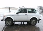
which replace the values of the variances of traditional meters, Figure 2. Mono, stereo forward-looking and omnidirectional
for a set of measurements of the visual channel, the weighted recording units installed on the roof of the Niva car.
average is calculated, where the readings with the greatest
reliability and accuracy have the greatest weight.
Figure 1. The general scheme of VS hardware and traditional
information systems combination for mobile robots information (a)
support. RU – recording unit (video camera) with a certain field
of view; CCU – computing control unit; GNSS – global
navigation satellite system.
We use one more technique to improve (improve the quality
and reliability) of the results in determining the trajectory of the
vehicle on which the visual sensors are installed. This technique
is as follows. As a unifying principle for all data, we take the
trajectory of the moving RTK. When constructing this
trajectory, we take into account such factors as the mechanical
characteristics of the mobile RTK and the likely need to build a
return path (solving the problem of returning to the starting
point in an autonomous mode). The algorithm for describing the
trajectory of a mobile robot is based on the approximation of
the data of the integrated navigation systems in the form of a
piecewise polynomial function (spline) of the 3rd order by the (b)
least squares method and checking the resulting spline for the
absence of loops (Sprunk, 2008).
The hardware part of the architecture of the onboard VS is
formed by reconfigurable combinations (network) of recording
(RU) and computational and control units (VUB), and the
software part is a large-scale software framework VS RT
(Boguslavsky et al., 2019). In fig. 1 shows the general layout of
the VS.
(c)
4. EXPERIMENTS RESULTS
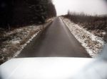
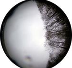
Figure 3. Examples of fields of view of the recording units:
The described approaches and corresponding algorithms were
(a) mono camera looking into a given area of space; (b) an
implemented within the framework of the real-time VS software
framework (Sokolov and Boguslavsky, 2016) and tested omnidirectional camera with a fisheye lens; (c) forward looking
experimentally at the test site, using the movement of the VS on stereo system.
a mobile platform along various routes. In fig. 2 shows a
general view of a car with VS units installed on it. In fig. 3
examples of fields of view of the recording units.
This contribution has been peer-reviewed.
https://doi.org/10.5194/isprs-archives-XLIV-2-W1-2021-201-2021 | © Author(s) 2021. CC BY 4.0 License. 203The International Archives of the Photogrammetry, Remote Sensing and Spatial Information Sciences, Volume XLIV-2/W1-2021
4th Int. Worksh. on “Photogrammetric & computer vision techniques for video surveillance, biometrics and biomedicine”, 26–28 April 2021, Moscow, Russia
As areas of images for the optical flow estimation the regions of consisting of two synchronized 5 Mp color cameras with 60°
interest in the VS fields of view of the recording units were lenses were used in the experiments. An integrated GPS
selected (fig. 4-6). receiver combining satellite and inertial navigation systems was
used as an additional means of arbitrarily recording
movements (SBG Systems, 2021).
At the current stage of research, the choice of benchmarks
remains with the operator performing supervisory control. VS
provides tracking of the specified landmarks and the solution of
the navigation problem. Building a map of the area and
determining its position on it (the so-called SLAM method
(Mur-Artal and Tardós, 2014)) is performed based on the
concept of interpretive navigation (IN) (Kirilchenko et al.,
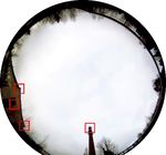
2008). Fig. 7 shows the objects selected as landmarks for
determining the position of the vehicle on the ground.
Figure 4. Area of interest for calculating the optical flow of a
monocular block.
(a)
Figure 5. of the stereo unit (one frame of the stereo system is
shown).
(b)
Figure 7. Examples of images of the registering blocks of the
VS layout. (a) Omnidirectional / panoramic cameras; (b) Stereo
system (a frame from one of the cameras is shown). Objects
that can be used as landmarks are marked with red squares.
Experiments have shown the effectiveness of the described
approach, high accuracy of determining the position (up to 1%
of the distance traveled), orientation (up to 0.3 angular degrees)
and other parameters that characterize the relative movement of
the vehicle was obtained. Naturally, the described combined
visual channel can be combined with other means of navigation:
inertial, satellite, wheel odometry, which makes it possible to
Figure 6. Additional areas of interest for calculating the optical increase the reliability of solving the navigation problem in a
flow in the case of a homogeneous underlying surface (a single wider class of conditions.
frame of the stereo system is shown).
5. CONCLUSIONS
As part of the VS, an omnidirectional camera with a 5 Mp color
The considered organization of information support for
matrix, a fisheye lens with a 360° viewing angle around the
purposeful movements of mobile vehicles using the visual
vertical axis and 90° relative to the horizon, and a stereo system
This contribution has been peer-reviewed.
https://doi.org/10.5194/isprs-archives-XLIV-2-W1-2021-201-2021 | © Author(s) 2021. CC BY 4.0 License. 204The International Archives of the Photogrammetry, Remote Sensing and Spatial Information Sciences, Volume XLIV-2/W1-2021
4th Int. Worksh. on “Photogrammetric & computer vision techniques for video surveillance, biometrics and biomedicine”, 26–28 April 2021, Moscow, Russia
channel in model assessments and experiments has shown high Sprunk, C., 2008. Planning Motion Trajectories for Mobile
efficiency. The algorithm for determining the trajectory of a Robots Using Splines. Report, Faculty of Applied Sciences,
moving vehicle based on the optical flow takes into account a Albert-Ludwigs-Universität Freiburg, Germany.
large number of factors that affect the reliability of the result
and uses different areas of several fields of view.
All the components of the described process of organizing
purposeful movements based on the use of the visual channel
continue to be improved. The database of objects that can be
selected as landmarks is being expanded, and algorithms for
automatically selecting such objects are being developed. A
notable feature of the described algorithms is their
implementation in the format of a unified modular software
framework for real-time vision systems. This implementation
allows you to quickly build software to solve new problems of
information support based on the use of VS.
REFERENCES
Boguslavsky, A.A. et al. 2019: Models and algorithms for
intelligent control systems. KIAM RAS, Moscow.
Howarth, P., Rueger S., 2004: Evaluating Texture
Characteristics for Content-Based Image Search. Proc. of the
International Conference on Image and Video Search, 326-334.
Ionova, J.N., Kiril’chenko, A.A., Pavlovsky, V.E., Platonov,
A.K., Pryanichnikov, V.E., 1988: Conditions for coordination
of the information and motion activities of mobile robots.
Preprints of the 3rd IFAC symposium Intelligent Autonomous
Vehicles, Madrid, Spain, March 25-27.
Kirilchenko, A.A., Platonov, A.K., Sokolov, S.M., 2008:
Theoretical aspects of the organization of interpretive the
navigation of a mobile robot. KIAM RAS Preprint No. 19.
Kiy, K.I., 2018: Image Understanding Systems Based on the
Geometrized Histograms Method. Extreme Robotics, 1(1), 417-
423.
Kolodnikova, N.V., 2004 : An overview of texture features for
image recognition tasks. TUSUR Reports, Automated systems
of information processing, control and design, 113-125.
Mur-Artal, R., Tardós, J., 2014. ORB-SLAM: Tracking and
mapping recognizable features. MVIGRO Workshop at Robotics
Science and Systems (RSS), Berkeley, USA.
Natesh, S., 2010: Feature Based Landmark Extraction for Real
Time Visual SLAM. Proceedings of the 2010 International
Conference on Advances in Recent Technologies in
Communication and Computing. 16-17 Oct.
SBG Systems, 2021. Ellipse Series. Miniature inertial sensors.
https://www.sbg-systems.com/products/ellipse-series/
Scaramuzza, D., Fraundorfer, F., 2011: Visual Odometry Part I:
The first 30 years. Robotics & Automation Magazine, 18(4), 80-
92.
Sokolov, S.M., Boguslavsky, A.A., 2016: Methodological
aspects for the development of information systems of
unmanned mobile vehicles. Proc. ICINCO16, vol. 2, 492-498.
This contribution has been peer-reviewed.
https://doi.org/10.5194/isprs-archives-XLIV-2-W1-2021-201-2021 | © Author(s) 2021. CC BY 4.0 License. 205You can also read


