Changes in granulation scales over the solar cycle seen with SDO/HMI and Hinode/SOT
←
→
Page content transcription
If your browser does not render page correctly, please read the page content below
A&A 652, A103 (2021)
https://doi.org/10.1051/0004-6361/202039436                                                                                                               Astronomy
c J. Ballot et al. 2021                                                                                                                                    &
                                                                                                                                                          Astrophysics

      Changes in granulation scales over the solar cycle seen with
                      SDO/HMI and Hinode/SOT
                                            J. Ballot1 , T. Roudier1 , J. M. Malherbe2,3 , and Z. Frank4

      1
          Institut de Recherche en Astrophysique et Planétologie (IRAP), Université de Toulouse, CNRS, UPS, CNES, 14 avenue Edouard
          Belin, 31400 Toulouse, France
          e-mail: jerome.ballot@irap.omp.eu
      2
          Observatoire de Paris, LESIA, 5 place Janssen, 92195 Meudon, France
      3
          PSL Research University, CNRS, Sorbonne Universités UPMC Univ. Paris 06 Univ. Paris Diderot, Sorbonne Paris Cité, Paris,
          France
      4
          Lockheed Martin Solar and Astrophysics Laboratory, 3251 Hanover Street, Palo Alto, CA 94303, USA

      Received 15 September 2020 / Accepted 25 May 2021

                                                                                     ABSTRACT

      Context. The Sun is the only star where the superficial turbulent convection can be observed at very high spatial resolution. The Solar
      Dynamics Observatory (SDO) has continuously observed the full Sun from space with multi-wavelength filters since July 2010. In
      particular, the Helioseismic and Magnetic Imager (HMI) instrument takes high-cadence frames (45 s) of continuum intensity in which
      solar granulation is visible.
      Aims. We aimed to follow the evolution of the solar granules over an activity cycle and look for changes in their spatial properties.
      Methods. We investigated the density of granules and their mean area derived directly from the segmentation of deconvolved images
      from SDO/HMI. To perform the segmentation, we define granules as convex elements of images.
      Results. We measured an approximately 2% variation in the density and the mean area of granules over the cycle, the density of
      granules being greater at solar maximum with a smaller granule mean area. The maximum density appears to be delayed by about one
      year compared to classical activity indicators, such as the sunspot number. We complemented this study with high-spatial-resolution
      observations obtained with Hinode/SOTBFI (Solar Optical Telescope Broadband Filter Imager), which are consistent with our results.
      Conclusions. The observed variations in solar granulation at the disc centre reveal a direct insight into the change in the physical
      properties that occur in the upper convective zone during a solar cycle. These variations can be due to interactions between convection
      and magnetic fields, either at the global scale or, locally, at the granulation scale.
      Key words. Sun: granulation – Sun: activity

1. Introduction                                                                                      Since July 2010, the Helioseismic and Magnetic Imager
                                                                                                 (HMI) instrument aboard the Solar Dynamics Observatory
Contrary to other stars, we are close enough to the Sun to                                       (SDO) spacecraft has provided images of solar granulation
be able to observe various physical properties of its surface                                    free of atmospheric perturbations with a moderate spatial res-
with high spatial resolutions (up to 180 km) and high tem-                                       olution and a temporal cadence of 45 s. These data provide
poral cadences (5–60 s). Convective elements, known as solar                                     an opportunity to determine the variation amplitude of gran-
granules, are visible from ground-based and space-based obser-                                   ulation parameters at the solar surface over several years. In
vatories. Satellites provide images without the terrestrial atmo-                                addition, we had access to high-resolution images of the solar
spheric distortions (seeing) and allow precise quantitative                                      granulation obtained with the 50 cm Solar Optical Telescope
measurements of granule physical properties. Although the main                                   (SOT) aboard the Hinode satellite between November 2006 and
characteristics of that granulation are widely described in the                                  February 2016.
literature (e.g., see Hirzberger et al. 2002; Nordlund et al. 2009;                                  Complex interactions between solar turbulent convection and
Lagg et al. 2014; Fischer et al. 2017; Falco et al. 2017), the stud-                             magnetic fields generate the quasi-periodic solar activity cycle.
ies of its variations over activity cycles are limited (see refer-                               The appearance of strong magnetic structures (spots, pores, etc.)
ences in Roudier & Reardon 1998; Muller et al. 2018). This is                                    at the photosphere level is known to locally modify the convec-
mostly due to the difficulty in acquiring homogeneous sets of                                    tion processes. Faurobert et al. (2018) have shown that activity-
granulation images without atmospheric distortions over a whole                                  induced variations in physical quiet-Sun structures, such as the
11-year solar cycle. Another method for tracking variations in                                   temperature gradient, might affect the irradiance. In this study
granulation properties consists in analysing the power spectrum                                  we look for global changes in granulation that would also affect
of solar radial-velocity or luminosity fluctuations. Using GOLF                                  the quiet Sun. Variations in solar granulation properties would
data, Lefebvre et al. (2008) looked for variations in solar gran-                                provide a direct insight into the change in physical properties
ular timescales with the activity cycle. However, they did not                                   occurring in the upper convective zone. Quantifying these varia-
find any significant variations correlated to the magnetic activity                              tions along a cycle would provide new observational constraints
because they were dominated by instrumental and orbital effects.                                 on interactions between convection and the magnetic field.

                                                                                                                                                                         A103, page 1 of 10

                Open Access article, published by EDP Sciences, under the terms of the Creative Commons Attribution License (https://creativecommons.org/licenses/by/4.0),
                                 which permits unrestricted use, distribution, and reproduction in any medium, provided the original work is properly cited.
A&A 652, A103 (2021)
Fig. 1. Progression of the central part of a processed image. Left: original image of solar granulation observed with HMI around the disc centre
with a pixel size of 000. 5 for a field of view of 10000 × 10000 . Middle: same image after deconvolution, with a pixel size of 000. 25. Right: same image,
segmented at the granulation level (each white element corresponds to a granule).
It has long been established that variations in solar granu- has already been successfully applied in Roudier et al. (2020).
lation represent only a few tens of parts per million of solar To limit projection effects, the field of view was restricted to
luminosity variations (Hudson & Woodard 1983). Nevertheless, 1000 × 1000 pixels around the disc centre. This corresponds to
we can observe the evolution of the dynamical properties of the about 25000 × 25000 , with a slight dependence on the distance to
granulation over a solar cycle. Thanks to Hinode observations, the Sun during the orbit. The conversion from arcseconds to kilo-
variations in intensity contrast and in granulation scales have metres takes into account the exact distance between the SDO
been shown to be smaller than 3% (Muller et al. 2018). satellite and the Sun.
We aim to go further with the present study, taking advan- Different techniques for extracting granules from each image
tage of SDO/HMI observations and using a new approach. We have been proposed over the years and were recently dis-
investigate the density of granules and their mean area, deriv- cussed by Roudier et al. (2020). For this current work, we
ing them directly from segmented images of the photosphere chose to extract each granule by using convexity detection, as
provided by SDO/HMI. In Sect. 2 we briefly describe the data done in Roudier et al. (2012). With this method, granules are
selection and the reduction pipeline we used to get the segmented identified as convex elements of the image. Contrary to other
images. In Sect. 3 we present the temporal evolution of granule approaches, such as watershed methods or the method developed
geometrical parameters and discuss the corrections we made. We by Bovelet & Wiehr (2001), the technique based on convexity is,
compare our results to complementary observations provided by by construction, independent of the image contrast and does not
Hinode/SOT in Sect. 4. In Sect. 5 we determine the contribution require free parameters that would have to be manually tuned for
of the magnetic network, before concluding in Sect. 6. different images. We thus applied a very homogeneous treatment
to all the images over nine years. A major flaw of the convexity
method is that it underestimates the granule size. This would
2. SDO/HMI data selection and reduction have been an issue if we wanted to measure absolute quanti-
ties, but it did not affect our study since we looked for relative
The HMI instrument (Scherrer et al. 2012; Schou et al. 2012) variations.
aboard SDO provides uninterrupted observations over the entire Due to our selection method (one frame per hour), five-
solar disc. This provides a unique opportunity to extract solar minute oscillations are still present in the data and may affect
granulation characteristics over a long time period with uniform our analysis. We thus performed tests on a time sequence with a
observation sets. 45 s time step to be able to filter out the five-minute oscillations,
Since data reduction is very time consuming, it was not pos- as done for example in Roudier et al. (2019). We thus verified
sible to reduce all available data; as such, we had to carefully that our segmentation technique is only weakly sensitive to these
pick our image set. We selected one day per month over nine oscillations.
years, starting on 1 July 2010, with a time step as regular as pos- Once the images were segmented, the final steps consisted
sible from available data in the Joint Science Operations Center in labelling and counting the granules. To reduce the impact of
(JSOC) data base. Such a monthly selection allows us to check noise, we discarded convex elements with an area of one pixel,
the orbital effects of the SDO satellite, which introduce annual that is, we only counted as granules convex elements with an
variations. For each selected day, we picked hourly images. We area greater than or equal to two pixels. Figure 1 shows the pro-
ensured, via visual inspection, that all images have good qual- gression of the central part of a processed image, from the raw
ity. We thus ended up with a set of 2711 SDO/HMI white-light HMI data to the final image – segmented at the granulation level
images. – via the deconvolved image.
The original pixel sizes of all the images are close to 000. 5;
the exact values were used to reduce and analyse the data. White-
light 4096 × 4096 images were deconvolved from the HMI trans- 3. Solar granule density and area over a solar cycle
fer function (Couvidat et al. 2016) and re-binned by a factor of
two, resulting in images with a size of 8192 × 8192. This oper- The deconvolved and segmented images, at the solar disc cen-
ation allowed us to increase the number of pixels for each gran- tre, allowed us to get the number of granules and their areas
ule and aided in the segmentation processing. Such a technique in the observed field of 1000 × 1000 pixels and to follow them
A103, page 2 of 10J. Ballot et al.: Changes in granulation scales over the solar cycle seen with SDO/HMI and Hinode/SOT
2011 2012 2013 2014 2015 2016 2017 2018 2019 We needed to understand the origin of this annual oscillation,
which is undoubtedly due to the analysis method or the instru-
ment itself. Thus, a detailed inspection of the data reduction pro-
0.51 cedure was required to determine which parameters can gener-
Density of granule (Mm−2)
ate such a fluctuation. Combinations of the orbit velocity, CCD
temperatures, and window temperature affect the measured fil-
0.50 tergram intensities (P. Scherrer, priv. comm.). Knowing this, we
checked three parameters that could be involved in the observed
0.49 residual annual variations: (i) the image contrast, (ii) the focus,
and (iii) the velocity of SDO/HMI relative to the Sun.
The first tested parameter was the contrast. Over their life
0.48 cycle, the detectors of HMI show a decrease in sensitivity (Fig. 6
in Hoeksema et al. 2018), which can also affect the contrast of
0.47 the solar granulation. To check this, we normalized the contrast
0 500 1000 1500 2000 2500 3000 3500 with the same mean for two days of the sequence and applied
Time (days) our reduction pipeline. As explained in Sect. 2, our segmen-
tation method, which is based on convexity, is mathematically
Fig. 2. Temporal evolution of the observed density of granules per Mm2
measured at the disc centre with SDO. Each cross corresponds to the
insensitive to the contrast. As expected, the numbers of granules
measurement obtained from an image. The time axis starts on 1 July detected with and without the contrast normalization are very
2010. The upper x-axis indicates observation years. similar. However, we must keep in mind that we only tested a
change in contrast without loss in image quality. Blurred images
(caused by e.g., de-focus effects) are lacking in both contrast and
sharpness.
over time. We detail in this section how we extracted the granule We then checked the density of granules relative to the image
density and granule area and how we corrected them for annual focus. During its journey, the SDO satellite receives direct solar
effects. flux as well as solar flux reflected by the Earth. The evolution
of that total flux modifies the temperature of several elements
3.1. Temporal evolution of the granule density (CCDs, windows, etc.) in the satellite, which in turn slightly
changes the focus. The uncontrolled window temperature is par-
Counting the number of granules in each frame was done by ticularly known to affect the focus (Hoeksema et al. 2018). The
labelling the segmented images. Of the 2711 values, four are quality of the focus is one of the parameters that could possi-
clear outliers (>10-σ); they were removed from the sample and bly influence our granule detection. To test that hypothesis, we
are not considered in the rest of the article. Thus, our final set mimicked de-focus effects by artificially degrading the modu-
was reduced to 2707 points. Due to the combination of the geo- lation transfer function (Couvidat et al. 2016) of an image. The
stationary and terrestrial orbit of the SDO satellite, the real field degraded image lost 1.85% in contrast; this only slightly affected
of view in square megametres (Mm2 ) on the Sun’s surface varies the number of detected granules, which was reduced by 0.45%.
by a few fractions of a percent over a year. The exact area in Mm2 It is difficult to push the blurring much further while still main-
of the observed field for each frame was determined by using the taining an acceptable image. Such a contrast variation (1.8%)
distance of SDO to the Sun given in the FITS file headers. The is representative of variations observed in real data over a day.
density of granules per Mm2 was then computed as the counted Over a year, the daily mean contrast varies by 2–3%. However,
number of granules divided by the exact observed area in Mm2 . we must keep in mind that other parameters (e.g., spatial resolu-
We needed to properly treat the edges of images since gran- tion in megametres) also affect the contrast, and hence the vari-
ules on image boundaries are cut, which impacts the mea- ation in contrast due to de-focussing is necessary smaller than
sured densities. To correct for this effect, we defined a border the total observed variation. Nevertheless, we found that when
zone as a six-pixel-wide band running along the boundaries of one increases the de-focussing to get 5% fewer detected gran-
images: Granules that were fully inside this zone were discarded, ules, the image contrast drops by at least 10%, far beyond what
whereas granules that straddled the frontier of this zone were is observed. Thus, changes in focus do not go far in explain-
counted with a weight representing the fraction of the granule ing the observed annual variations; these changes may, however,
inside the image. For example, if 60% of the area of a granule is contribute to the dispersion measured over a day.
inside the boundary zone and 40% inside the image, this granule Finally, intensity measurements could also be affected by
is count as 0.4 when computing the density. the high velocity of SDO relative to the Sun, Vr . To check the
Neglecting to correct for edge effects induces a systematic impact of Vr , we selected three data subsets corresponding to
overestimation of the density of 0.2%. Nevertheless, this bias is three different ranges in velocity: maximum (Vr > 2 km s−1 ),
very stable from one image to another (image-to-image fluctua- mean (−0.1 < Vr < 0.1 km s−1 ), and minimum (Vr < −2 km s−1 ).
tions are an order of magnitude smaller), and thus we are very Figure 3 shows the density of granules for these three samples.
confident that our correction does not introduce spurious varia- The Vr component does not appear to be involved in the observed
tions in this study. annual variation since the measurements show a distribution over
Figure 2 shows the temporal evolution of the density of gran- the whole curve, regardless of the amplitude of Vr .
ules (in Mm−2 ) during the cycle. There is still an annual vari- During its journey, SDO does not observe the Sun from the
ation in the amplitude of around 5%, which is clearly visible same direction: The B0 angle varies with a one-year period.
in the density evolution despite the field-of-view size for each This means that the field of view is centred on solar latitude
image being taken into account. Nevertheless, a global change −7.26◦ in early September and 7.26◦ in early March. We can-
over the cycle is visible: We notice an increase in the first half not imagine a physical reason linking B0 to the measured gran-
and a decrease in the second half. ule number – except if there were a never-before-seen strong
A103, page 3 of 10A&A 652, A103 (2021)
2011 2012 2013 2014 2015 2016 2017 2018 2019
0.51
Density of granule (Mm−2)
0.51
Density of granule (Mm−2)
0.50
0.50
0.49
0.49
0.48
0.48 Vr maximum
Vr mean
Vr minimum 0.47
0.47 0.0325 0.0330 0.0335 0.0340 0.0345
0 500 1000 1500 2000 2500 3000 3500 Pixel area (Mm2)
Time (days)
Fig. 4. Granule density as a function of the pixel area. The solid line is
Fig. 3. Similar to Fig. 2 but the data have been split into three categories, a fitted second-order polynomial.
corresponding to three different ranges of radial velocity, Vr , of the SDO
satellite (maximum, mean, or minimum; see the main text for details).
one observed in the real data. We conclude that the changes in
Table 1. Variations in the determination of the mean granule area, the pixel size with the distance of SDO to the Sun generate the arti-
granule filling factor, and the granule density between two artificial ficial oscillation visible in Fig. 2.
observations of the same granulation simulation: one using a pixel area
corresponding to SDO perihelion, the other to SDO aphelion.
3.3. Corrected granule density
Perih./Aph. Due to the sensitivity of our measurement on the pixel size,
we cannot infer any conclusions about variations shorter than
Mean granule area −3.3% one year. However, we can directly compare the granule den-
Filling factor +0.6% sity obtained from images with the same pixel size. Thus, we
Granule density +4.0% can recover relevant variations over a decade since, year after
year, at the same epoch the pixel size is the same. As a conse-
quence, the global variation of about 1–2% visible in Fig. 2 is
dependence on the latitude. Moreover, the B0 variation is not
not explained by pixel size variations. We thus wanted to sep-
in phase – nor in antiphase – with the measured density. Indeed,
arate this long-term variation from any variations generated by
every 6 months (early June and early December) the field of view
the pixel size.
is centred on the solar equator (B0 = 0◦ ), but the mean density is
Figure 4 shows the tight correlation between the pixel area
∼0.49 in June and ∼0.51 in December. Thus, B0 is not a relevant
and the measured granule density. We performed a second-order
parameter for explaining the annual oscillation.
polynomial fit to model this smooth relation. We then used this
fit to calibrate the granule density: We normalized the measured
3.2. Impact of the pixel area quantities with the fitted relation. Doing so, we needed to use an
arbitrary reference value. As a consequence, only relative vari-
Since the parameters described above did not allow us to under- ations are meaningful. Figure 5 displays the corrected granule
stand the observed annual variation, we continued our inspection density during the cycle.
of the parameter space. A detailed inspection of the granule bina- For each selected day, we got hourly measurements. We thus
rization revealed that the segmentation process, by convexity have 24 values every day (except for three days, for which one or
detection, is sensitive to the pixel size in megametres. This sensi- two values are missing), which were averaged to compute daily
tivity is due to the fact that the smallest granules have a size close mean values. We computed error bars of these means by assum-
to that of the pixel, even after deconvolution and re-binning at ing that daily standard deviations are representative of errors
000. 25. Thus, with larger pixels, the segmentation method misses of individual measurements (typically σ ≈ 0.0022 Mm−2 ). To
the smallest granules, which reduces the measured density – and compute daily errors, we also assumed that each measurement
increases the measured mean area (see Sect. 3.4). We are close to is statistically uncorrelated to the others. This is ensured by the
the detection limit, but, as shown in Fig. 1, granules are clearly fact that two consecutive segmented images are significantly dif-
visible and segmented. ferent since granule lifetimes (8−200 ) are shorter than the time
To quantify the effect of the pixel size on our segmenta- between two measurements (1 hr).
tion, we used the solar granulation simulation performed by We compared the evolution of granule density with the evo-
Stein & Nordlund (2000) to generate artificial observations of lution of the 13-month smoothed monthly mean total sunspot
the photosphere with two different pixel sizes, one correspond- number (SILSO World Data Center 2008-2019)1 , which is used
ing to the SDO perihelion and the other to the aphelion. We then as a proxy for the solar magnetic activity (see the solid line in
compared the mean granule area, the granule filling factor, and Fig. 5). We observe that the granule density increases with mag-
the granule density. Table 1 summarizes the comparison of these netic activity and that the granule density then decreases when
three quantities between these extreme positions. We observe a the activity decreases. We notice that the maximum in density
clear impact of the pixel size on the granule density and mean
area due to the segmentation processing. The amplitude of the 1
International Sunspot Number Monthly Bulletin and online cata-
granule density variation reported in Table 1 is the same as the logue: https://wwwbis.sidc.be/silso/
A103, page 4 of 10J. Ballot et al.: Changes in granulation scales over the solar cycle seen with SDO/HMI and Hinode/SOT
2011 2012 2013 2014 2015 2016 2017 2018 2019 2011 2012 2013 2014 2015 2016 2017 2018 2019
0.495
Corrected granule density (Mm−2)
0.50
Mean granule area (Mm2)
0.490
0.49
0.485 0.48
0.480 0.47
0.46
0.475
0.45
0 500 1000 1500 2000 2500 3000 3500 0 500 1000 1500 2000 2500 3000 3500
Time (days) Time (days)
Fig. 5. Density of granules per Mm2 corrected for the pixel area. Dots Fig. 7. Temporal evolution of the observed mean granule area measured
correspond to individual measurements, and crosses show daily aver- at the disc centre with SDO. Each cross corresponds to the measurement
ages with estimated error bars. We recall that we selected one single day obtained from an image. The time axis starts on 1 July 2010.
for each month of the observation period. Dates where spots (pores) are
present in the field of view are indicated with red (blue) symbols. Vari-
ations of the 13-month smoothed monthly mean total sunspot number
(SILSO World Data Center 2008-2019: International Sunspot Number 3.4. Temporal evolution of the corrected mean granule area
Monthly Bulletin and online catalogue, https://wwwbis.sidc.be/
From the segmented images, we also computed the mean area
silso/) are overplotted (solid line).
of granules. This is a complementary indicator that can be com-
pared with the density, even if it is not fully independent. The
1000 density only relies on the count of segmented elements, and the
mean area also takes their sizes into account. A representative
800 histogram of granule sizes is plotted in Fig. 6. As discussed in
the previous section, the distribution is cut towards the small
granules. As mentioned in Sect. 2, we rejected one-pixel ele-
600 ments. We conducted complementary tests by also rejecting big-
Number
ger granules (up to five pixels); the results of these tests did
400
not call into question any of the conclusions presented in this
section.
We thus computed the mean granule area in every image
200 in pixels and converted it to Mm2 using the real pixel size in
megametres. As for computing the density, we carefully treated
0
the boundaries of images: When we computed the mean granule
0 10 20 30 40 50 area, we discarded the granules that are inside the boundary zone
Granule area (pix) (see the definition in Sect. 3.1), and we considered granules only
if at least half of their surface lay inside the image. Once this was
Fig. 6. Mean distribution of the granule area (in number of pixels) in the done, we performed exactly the same analyses as for the density.
observed field of view on 1 July 2010. The shadowed bin corresponds
Figure 7 shows the temporal evolution of the mean granule
to the one-pixel-size elements that are rejected.
area (similar to Fig. 2). As for the density, the evolution is dom-
inated by an annual oscillation – due to variations in the pixel
is delayed by 300−400 days compared to the activity maximum. size – superimposed on a global trend. All tests and the verifica-
The beginning of the decay is slow, with a lot of fluctuations, but tion described in Sect. 3.1 were conducted and led to the same
it drops markedly over the two last years and reaches its min- conclusions.
imum values during the solar minimum. The amplitude of the Like the granule density, the measured mean granule area
variation is about 2% (2.5% peak-to-peak). is strongly impacted by the pixel size. Therefore, we applied
Finally, we wanted to ensure that these variations do not the same procedure to correct them. Figure 8 shows the rela-
originate in the pollution of images with magnetic structures. tion between the mean granule area and the pixel area (similar
Of course, when the activity is higher, there is a higher risk of to Fig. 4). We fitted a polynomial to model this tight relation and
finding spots, or simply pores, in our field of view. Such mag- used it to correct our measurements for this effect.
netic structures may pollute our estimates of the granule den- Corrected mean granule areas are plotted in Fig. 9 (similar
sity. We thus went through all 2711 images to identify the dates to Fig. 5). We also performed daily averages and compared their
where spots or pores appeared in our field of view. These dates evolution to the sunspot number; the points that are potentially
are labelled with distinctive colours (red and blue) in Fig. 5. We affected by spots and pores are identified with coloured symbols
thus confirm that the trends are unchanged when these points are in the figure. A very clear trend appears in this plot. This trend
discarded. We also notice that the part exhibiting the greatest dis- remains very clear even with measurements affected by mag-
persion corresponds to the period where the field is more often netic structures discarded. The mean granule area decreases as
polluted by magnetic structures and that the strongest outliers activity increases and reaches a minimum on days 1700−1800,
actually correspond to images affected by magnetic structures. which corresponds to the maximum in granule density; the mean
A103, page 5 of 10A&A 652, A103 (2021)
0.50
Mean granule area (Mm2)
0.240
0.49
Filling factor
0.48 0.239
0.47
0.238
0.46
0.45
0.0325 0.0330 0.0335 0.0340 0.0345 0 500 1000 1500 2000 2500 3000 3500
Pixel area (Mm2) Time (days)
Fig. 8. Mean granule area as a function of the pixel area. The solid line Fig. 10. Evolution of the measured daily-averaged filling factor of gran-
is a fitted second-order polynomial. ules computed as the product of their mean area and density. Data points
affected by spots or pores have been removed. A straight line indicates
2011 2012 2013 2014 2015 2016 2017 2018 2019 a linear fit.
0.505
with a spatial resolution of about 000. 2 at a wavelength of
Corrected mean granule area (Mm2)
550 nm. For our study, we used blue continuum observations at
0.500
450.45 nm from the Hinode/SOT broadband filter imager (BFI).
We selected 191 observations over eight years (2008–2016) with
0.495 a time step as regular as possible. The selected sample is limited
for mainly two reasons. First, the dataset stops in 2016 due to
0.490 the failure of the BFI camera. Second, a large part of the Hin-
ode/SOT observations were done within the G band (∼430 nm),
0.485 which cannot be exploited with our segmentation technique due
to the presence of numerous inter-granular bright spots.
0.480 After flat field and dark corrections, SOT data were cor-
rected for the constantly decreasing flux due to the degradation
0 500 1000 1500 2000 2500 3000 3500 of the optics over time. In order to limit this temporal variation,
Time (days)
all image contrasts were normalized while keeping the average
Fig. 9. Mean granule area corrected for the pixel area (same meanings of each image at their original values. The field of view was
as in Fig. 5). 2038 × 1014 pixels, giving 22200 × 110.500 with a pixel size of
000. 1089. The transformation from arcsecond into kilometre takes
the distance between the satellite and the Sun into account.
granule area then increases again when the activity weakens. These observations overlap with our SDO series for about
As for the density, in the second half the measurements start to 5.6 years (from July 2010 to February 2016). Compared to
increase with a lot of fluctuations, before increasing smoothly SDO/HMI, Hinode observations provide a greater spatial reso-
over the two last years. The variation amplitude is around 2% lution: The optical resolution is five times better, and thus the
(about 2.5% peak-to-peak if considering only a pure quiet Sun). images do not need to be deconvolved. On the other hand, the
We thus recover consistent results between the density and temporal sampling is ten times smaller and the exploited field of
mean area of granules because we expect them to be anti- view twice smaller, drastically reducing the statistical sample.
correlated. Indeed, we expect the filling factor of granules to As done with the SDO data, the granule segmentation was
be constant over time since the variations in irradiance due performed by using convexity detection. We then applied exactly
to granulation over the cycle is smaller than 0.01% (e.g., the same procedure as described above to compute the granule
Hudson & Woodard 1983). The filling factor is nothing but the density and mean granule area. To be consistent, we also cor-
product of the density by the mean area and is plotted in Fig. 10. rected them for pixel-size effects, despite the fact that the pixel
We recovered a flat profile of this product by excluding points size, due to the higher resolution, has a lot less influence. The
affected by spots and pores. We nevertheless noticed a very slow corrected granule density and mean area are plotted in Figs. 11
and continuous decrease over nine years (∼0.2%) that is not and 12.
correlated with the cycle. We attributed such a slow decay to For both quantities, very large dispersion make it difficult to
instrument ageing (especially the ageing of detectors, electron- draw significant conclusions. However, while the granule density
ics, optics, etc.), which may slowly degrade the image quality. shows hardly any visible variation, a marginal trend appears in
the mean granule area, which seems to decrease when activity
4. Comparison with the Hinode dataset increases.
The granule density seems noisier than the mean granule
To complement this analysis only relying on one instrument, area. Indeed, with Hinode we observe many more small gran-
we wanted to analyse high-spatial-resolution data from the ules than with SDO thanks to its higher spatial resolution. The
SOT aboard the Hinode spacecraft (e.g., Suematsu et al. 2008; total number of granules detected with Hinode (and hence the
Ichimoto et al. 2004). The SOT has a 50 cm primary mirror density) is more impacted by the large population of small
A103, page 6 of 10J. Ballot et al.: Changes in granulation scales over the solar cycle seen with SDO/HMI and Hinode/SOT
1.10
Density of granule per Mm2
1.05
1.00
0.95
0.90
0 1000 2000 3000
time (days)
Fig. 11. Temporal evolution of the granule density obtained from Hin-
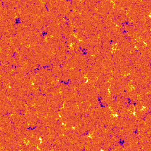
ode observations. Density is corrected for the pixel area. Variations in Fig. 13. HMI magnetogram corresponding to the first analysed field.
the monthly mean total sunspot number are overplotted (solid line). The The colour scale indicates the magnetic field strength from −100 G (pur-
time axis starts on 20 February 2008. ple and black) to 100 G (yellow and white). Green contours show the
borders of our mask.
0.39
Corrected mean granule area (Mm2)
0.38 1.51 ± 0.05%. We conclude that both datasets are in agreement
and that, despite being noisier, Hinode observations confirm the
0.37 change in the granulation scale detected with SDO/HMI on the
considered interval.
0.36
0.35 5. Impact of plages and the magnetic network
In previous sections we focus on the quiet Sun by excluding
0.34
images polluted by spots or pores. Going a step further, we
0.33
wanted see whether the observed variations are related to plage
0 1000 2000 3000 regions or to active network structures (e.g., Foukal & Lean
Time (days) 1988) or whether granulation variations are still present in the
inter-network.
Fig. 12. Temporal evolution of the mean granule area obtained from To achieve this objective, we took advantage of magne-
Hinode observations. The granule area is corrected for the pixel area. tograms that are simultaneously provided by HMI with each
Variations in the sunspot number are overplotted (solid line). The
straight dashed red line is a linear regression. The short, thick verti-
white-light image. From each magnetic map, we built a mask
cal line indicates the starting date of our SDO observation set (1 July according to the following four-step procedure: (1) All pixels
2010). The time axis starts on 20 February 2008. above a given threshold (30 G) were set in the initial mask. (2)
We applied a closing operator (a dilatation followed by an ero-
sion operation) to gather close structures. (3) We applied an
granules than with SDO. However, the mean granule area opening operator (an erosion followed by a dilatation opera-
appears to be less affected since we are averaging areas and not tion) to remove isolated pixels, which are generally generated
just counting them. We thus focused on this quantity and per- by noise. (4) We finally applied a dilatation operation to provide
formed some statistical analyses. a safety margin. Steps 2 and 3 were introduced to avoid masks
As presented in Sect. 3.4, the mean granule area decreases with a lot of unnecessary small holes or small islands.
during the first ∼1750 days of the SDO/HMI time series. Hence, Such a mask is shown Fig. 13. We conducted various tests to
we analysed mean granule area observed with Hinode on the build masks using slightly different methods (by skipping steps
same time interval (1750 days from 1 July 2010). We first needed 2 and 3 or by slightly modifying the threshold from 20 to 50 G),
to estimate the errors of our measurements. To do so, we per- but the conclusions of this section remained unchanged.
formed a full analysis of a 24-hour sequence and computed the We then measured the density and mean granule area outside
standard deviation. We thus estimated the relative error of mea- the mask using the same procedure as the one developed to prop-
surements at 1.1% (typically 0.004 Mm2 ). Taking these errors erly deal with borders. Nevertheless, we wanted to ensure that
into account, we performed a linear regression on that interval our masks did not introduce spurious variations. Masks with a lot
and recovered a decay (see Fig. 12). Interestingly, the decay is of structures may affect the measurements more than masks with
statistically more probable than a constant value: After compar- fewer structures. We used some artificial observations (derived
ing the χ2 of a linear model with that of a constant model, we from simulations; see Sect. 3.2) to which we applied all our
rejected the latter with a p value ≈ 10−5 . From the linear fit, we masks. In this artificial observation, as the granulation distribu-
derived that the mean granule area had decreased by 1.61±0.36% tion is statistically spatially homogeneous, we had to recover a
over this time interval. We then performed the same regression consistent measured density and mean granule area with all of
over the same interval using SDO/HMI and found a decrease of the masks. We actually do not find any significant bias in the
A103, page 7 of 10A&A 652, A103 (2021)
2011 2012 2013 2014 2015 2016 2017 2018 2019 6. Conclusion
0.495 In this paper we report the detection of variations in granule den-
Corrected granule density (Mm−2)
sity and mean area over the period 2010–2019. We conclude
that, once annual spurious effects are corrected for, a variation
0.490
of about 2% in the granulation scale occurs during the solar
cycle, the granules being the smallest about one year after the
0.485 Sun reaches its maximal activity. These changes are detected
clearly with HMI/SDO, and Hinode observations show consis-
tent and significant, if noisier, variations. We also showed that
0.480
while small magnetic structures of the network may explain a
part of these variations, we still observe variations in the inter-
0.475 network regions.
We stress that we only recovered relative variations; the
0 500 1000 1500 2000 2500 3000 3500 absolute values we report are not meaningful for several rea-
Time (days) sons. First, the granule detection technique we have used is very
robust but underestimates the granule surface. Second, we miss
Fig. 14. Density of granules per Mm2 corrected for the pixel area in
the smallest granules due to our limited resolution. As a side
the inter-network. This figure is similar to Fig. 5, but masks have been
applied to remove regions with a magnetic field stronger than 30 G. effect, our absolute measurement is sensitive to the pixel size
Fig. 13 shows such a mask. (which changes during the SDO orbit) because the cutoff of
the observed granule size distribution is consequently moving.
Luckily, we were able to correct for the impact of the pixel size
and recover long-term variations. Nevertheless, we must keep in
2011 2012 2013 2014 2015 2016 2017 2018 2019
mind that, because of this ad hoc correction, variations with peri-
0.510 ods shorter than one year (i.e. the orbital period) must be treated
Corrected mean granule area (Mm2)
cautiously and may still be polluted.
We carefully verified whether the instrument or the anal-
0.505
ysis method could have generated the observed variations. Of
course, despite our careful inspection, we may have missed a
hidden parameter; furthermore, we have not addressed the pos-
sible effects of ageing, which leads to a lower mean contrast of
0.500
HMI images. Even though we verified that a change in contrast
alone does not affect our segmentation method, this could be
a sign of an underlying degradation in image quality or sharp-
0.495 ness over time. Such a degradation would affect our segmen-
tation method as de-focussing would (see Sect. 3.1). The slow
decay observed in the filling factor is probably a sign that a
0 500 1000 1500 2000 2500 3000 3500
degradation has been occurring. Here is one possible explana-
Time (days) tion: With time, as images become (slightly) more degraded, in
similar situations we would less easily detect the small granules,
Fig. 15. Mean granule area corrected for the pixel area in the inter- which may reduce the filling factor. Of course, this should also
network. This figure is similar to Fig. 9, but masks have been applied to affect the measured density – which should decrease – and mean
remove regions with a magnetic field stronger than 30 G. Fig. 13 shows area – which should increase. Nevertheless, we are confident that
such a mask. the ageing does not provoke the reported 2% variation since the
impact of ageing is monotonic with time, whereas the observed
granulation scales decrease then increase again. Thus, even if
measurements of the granulation density or the mean area made we would have to correct the evolution of mean area (respec-
with any of the masks. tively, density) for a global increase (respectively, decrease) due
We applied masks to our real HMI dataset, measured the to ageing, the V-shape of the curve would remain and only the
granule density and mean area, and corrected them for pixel-size amplitude would be (slightly) affected.
effects. Results are shown Figs. 14 and 15, which can be com- We report, for the first time, a direct measurement of gran-
pared to Figs. 5 and 9. First, the density is in average slightly ule variations in the quiet Sun along the cycle; indirect clues
lower than in the full frame. This is consistent with theoretical of global modifications in granulation (integrated over the whole
expectations: Where the magnetic field is weaker, granules are Sun) had already been suggested by variations in Fraunhofer line
expected to be larger. We also notice that the measured mean bisectors (e.g., Livingston 1982; Livingston et al. 1999). More-
area appear slightly noisier than the density. Second, the varia- over, previous works indicated that variations in granulation dur-
tions observed along the solar cycle are weaker but still present. ing the cycle could be only of weak amplitude (Muller et al.
We can conclude that although small magnetic structures of the 2018); here we were able to sufficiently lower our detection
network explain a part of the variations reported in previous sec- level thanks in particular to the high stability and quality of the
tions, there are also variations in the inter-network regions. SDO/HMI instrument.
We can also use dedicated masks to clean spots and pores as Effects of magnetic fields on granulation have already been
well as plages from the images. We made this effort and present observed on the Sun: for example, it has been established that
the results in Appendix A. They are fully consistent with what is granules in magnetic plages are smaller than those in the quiet
presented in Sects. 3.3 and 3.4. Sun (e.g., Title et al. 1992; Narayan & Scharmer 2010). Indeed,
A103, page 8 of 10J. Ballot et al.: Changes in granulation scales over the solar cycle seen with SDO/HMI and Hinode/SOT
it can be shown that convective cells are shrunk in a verti- Acknowledgements. This work was granted access to the HPC resources of
cal magnetic field because the critical horizontal wavelength CALMIP under the allocation 2011-[P1115]. We are grateful to SDO/HMI and
of convective instability lowers when a vertical magnetic field Hinode teams. Sunspot data are from the World Data Center SILSO, Royal
Observatory of Belgium, Brussels (http://www.sidc.be/silso/). We thank
grows (e.g., Chandrasekhar 1961). Thus, a global change in the anonymous referee for her/his insightful comments, which have improved
the solar poloidal magnetic field may affect the granule size. the paper.
Nevertheless, the interactions between solar convection and the
magnetic field are complex and subtle and may occur at the References
global scale or locally at the granule scale. Quantifying the
changes in terms of magnetic fields would require detailed mod- Bastien, F. A., Stassun, K. G., Basri, G., & Pepper, J. 2013, Nature, 500, 427
Bovelet, B., & Wiehr, E. 2001, Sol. Phys., 201, 13
elling that is beyond the scope of this study. This paper brings Bugnet, L., García, R. A., Davies, G. R., et al. 2018, A&A, 620, A38
two new observational constraints for magnetohydrodynamics Chandrasekhar, S. 1961, Hydrodynamic and Hydromagnetic Stability (Oxford:
models: the amplitude of the change and the ∼1-year phase Clarendon Press)
shift relative to classical activity indicators, such as the sunspot Couvidat, S., Schou, J., Hoeksema, J. T., et al. 2016, Sol. Phys., 291, 1887
number. Falco, M., Puglisi, G., Guglielmino, S. L., et al. 2017, A&A, 605, A87
Faurobert, M., Carbillet, M., Marquis, L., Chiavassa, A., & Ricort, G. 2018,
In this paper we have described the evolution of the granule A&A, 616, A133
properties at the disc centre (i.e. at low latitude only). It would Fischer, C. E., Bello González, N., & Rezaei, R. 2017, A&A, 602, L12
be very useful to extend this study to higher latitudes to verify Foukal, P., & Lean, J. 1988, ApJ, 328, 347
whether the trend continues. Indeed, the latitudinal structuring of García, R. A., & Ballot, J. 2019, Liv. Rev. Sol. Phys., 16, 4
Hirzberger, J., Bonet, J. A., Sobotka, M., Vázquez, M., & Hanslmeier, A. 2002,
the solar magnetic field evolves significantly over a cycle. There- A&A, 383, 275
fore, mapping the granulation scales both in time and in latitude Hoeksema, J. T., Baldner, C. S., Bush, R. I., Schou, J., & Scherrer, P. H. 2018,
is perfectly relevant. Due to projection effects, segmentation pro- Sol. Phys., 293, 45
cesses at high latitude may be more delicate and require more Hudson, H. S., & Woodard, M. F. 1983, in Bulletin of the American
Astronomical Society, BAAS, 15, 715
care. This will be the subject of a future study. Ichimoto, K., Tsuneta, S., Suematsu, Y., et al. 2004, in Optical, Infrared, and
For stars other than the Sun, it is possible to recover global Millimeter Space Telescopes, ed. J. C. Mather, et al., SPIE Conf., 5487, 1142
information about granulation through temporal photometric Kahil, F., Riethmüller, T. L., & Solanki, S. K. 2019, A&A, 621, A78
observations by computing indexes such as the ‘8 hr Flicker’ Lagg, A., Solanki, S. K., van Noort, M., & Danilovic, S. 2014, A&A, 568, A60
Lefebvre, S., García, R. A., Jiménez-Reyes, S. J., Turck-Chièze, S., & Mathur,
(Bastien et al. 2013) or the so-called FliPer (Bugnet et al. 2018), S. 2008, A&A, 490, 1143
or simply by extracting granulation timescales and amplitudes Livingston, W. C. 1982, Nature, 297, 208
from power spectra (e.g., García & Ballot 2019, and references Livingston, W., Wallace, L., Huang, Y., & Moise, E. 1999, in High Resolution
therein). Santos et al. (2018) studied the temporal variations in Solar Physics: Theory, Observations, and Techniques, eds. T. R. Rimmele,
granulation timescales in Kepler solar-like stars. They did not K. S. Balasubramaniam, & R. R. Radick, ASP Conf. Ser., 183, 494
Muller, R., Hanslmeier, A., Utz, D., & Ichimoto, K. 2018, A&A, 616, A87
find a general link between activity and granulation for most Narayan, G., & Scharmer, G. B. 2010, A&A, 524, A3
of the stars. For one star (KIC 10644253), characteristic gran- Nordlund, Å., Stein, R. F., & Asplund, M. 2009, Liv. Rev. Sol. Phys., 6, 2
ulation timescales show variations correlated with magnetic Roudier, T., & Reardon, K. 1998, in Synoptic Solar Physics, ed.
activity indexes. However, they report variations in granulation K. S. Balasubramaniam, eds. J. Harvey, & D. Rabin, ASP Conf. Ser., 140,
455
timescales of around 20% that are directly correlated to the Roudier, T., Rieutord, M., Malherbe, J. M., et al. 2012, A&A, 540, A88
activity. This is the opposite of our present results, which also Roudier, T., Malherbe, J. M., Stein, R. F., & Frank, Z. 2019, A&A, 622, A112
have a much lower amplitude. Nevertheless, we must remem- Roudier, T., Malherbe, J. M., Gelly, B., et al. 2020, A&A, 641, A50
ber that these Kepler observations are averaged over the whole Santos, A. R. G., Campante, T. L., Chaplin, W. J., et al. 2018, ApJS, 237, 17
stellar photosphere and are not only of quiet areas. Beyond solar Scherrer, P. H., Schou, J., Bush, R. I., et al. 2012, Sol. Phys., 275, 207
Schou, J., Scherrer, P. H., Bush, R. I., et al. 2012, Sol. Phys., 275, 229
physics, our objective is to better understand stellar surface con- Stein, R., & Nordlund, A. 2000, Sol. Phys., 192, 91
vection and its interactions with magnetic fields, using the Sun Suematsu, Y., Tsuneta, S., Ichimoto, K., et al. 2008, Sol. Phys., 249, 197
as a close plasma physics laboratory. Title, A. M., Topka, K. P., Tarbell, T. D., et al. 1992, ApJ, 393, 782
A103, page 9 of 10A&A 652, A103 (2021)
Appendix A: Masking spots, pores, and plages 2011 2012 2013 2014 2015 2016 2017 2018 2019
0.505
Corrected mean granule area (Mm2)
2011 2012 2013 2014 2015 2016 2017 2018 2019
0.495 0.500
Corrected granule density (Mm−2)
0.495
0.490
0.490
0.485
0.485
0.480
0.480
0.475 0 500 1000 1500 2000 2500 3000 3500
Time (days)
0 500 1000 1500 2000 2500 3000 3500 Fig. A.2. Mean granule area corrected for the pixel area. This figure is
Time (days) similar to Fig. 7, but masks have been applied to remove structures with
a magnetic field stronger than 200 G.
Fig. A.1. Density of granules per Mm2 corrected for the pixel area. This
figure is similar to Fig. 5, but masks have been applied to remove struc-
tures with a magnetic field stronger than 200 G.
measure the density of granules and the mean granule area.
The masks we developed in Sect. 5 in order to isolate the mag- Results are shown in Figs. A.1 and A.2, which can be directly
netic structures of the solar network can be applied to remove compared to Figs. 5 and 9, respectively. As expected, the black
spots and pores, as well as plages, in images that are polluted by symbols, which correspond to images that are tagged as contain-
them. ing no spots or pores, are practically the same, whereas blue and
We thus constructed masks to remove magnetic structures red symbols are less scattered in Figs. A.1 and A.2 compared to
above 200 G (this threshold was chosen according to litera- Figs. 5 and 9. The improvement is mainly visible for the evolu-
ture, e.g., Kahil et al. 2019) and applied our full procedure to tion of the mean area.
A103, page 10 of 10You can also read