APA FDR Answers To Committee Questions - B. Rebel, C. Touramanis, J. Evans September 1-2, 2021
←
→
Page content transcription
If your browser does not render page correctly, please read the page content below
APA FDR Answers To
Committee Questions
 B. Rebel, C. Touramanis, J. Evans

                                September 1-2, 2021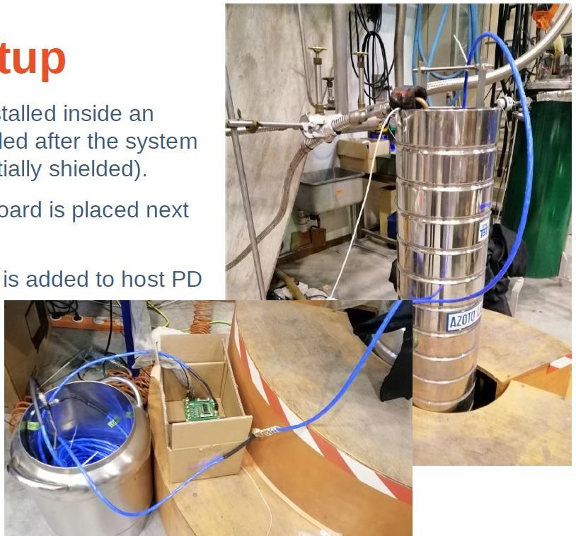
Questions from First Day

                           2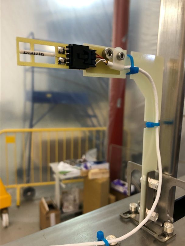
Can you please provide details for the RTD's including a bill of material,
schematic, and justification for why specific things were chosen for the
RTD's? (e.g. types of cables, the insulation, the connectors, etc...)

●   The CALCI consortium is responsible for specifying these details of the RTDs,
    while the APA consortium is responsible for providing mounting points for the
    RTDs and real estate for the cable runs
●   We agree that the concerns raised are important to address for the whole of
    DUNE to ensure stable operation of the detector
●   ProtoDUNE experience showed that RTDs, either on the APA itself or anywhere
    inside the Cold Box, can introduce noise. As long as we can easily ground the
    whole RTD system externally we are safe.
●   We contacted Anselmo Cervera to answer these questions

                                                                                    3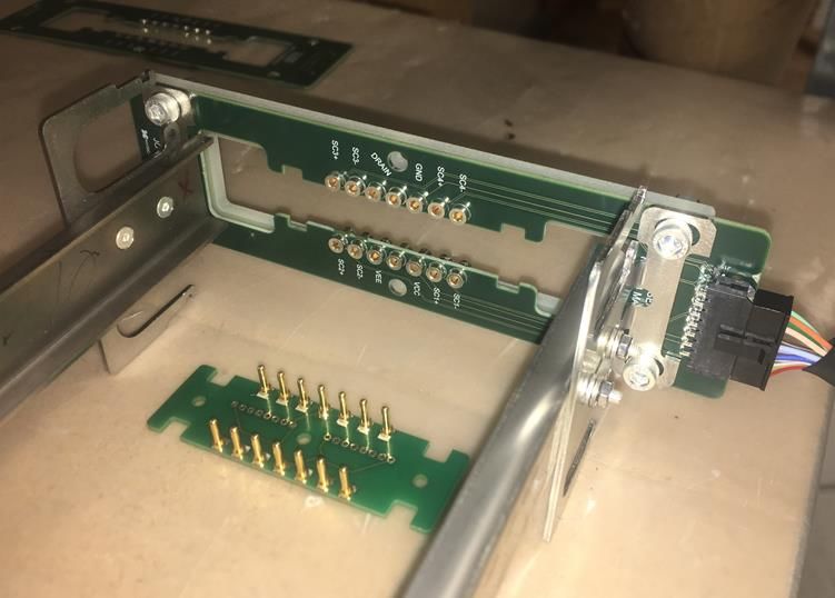
APA temperature sensors
 • Design choices:
        • Use photon detector cable routing and connectors
        • Number of sensors (4 per APA) limited by cable routing
        • Materials choice: Stainless steel, teflon and FR4
        • RTDs  are decoupled from the rest (intermediate IDC-4 connectors) to allow precise calibration and
          avoid unnecessary manipulation during installation

        • Uninterrupted 1 mA DC current
        • quad-twisted
          sensor’s end
                       cables with external EMC shielding individually grounded   at flange and floating at

                                                                        Frame
                                                                        sensor
                                            LAr
                                            sensor

Anselmo Cervera Villanueva, IFIC-Valencia               1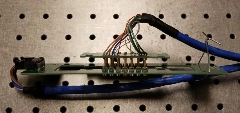
APA temperature sensors
 https://edms.cern.ch/project/CERN-0000206730    (Glass-filled polyester (PBT))
                                                IDC-4 male         IDC-4 female
                                                connector          connector
             RTD
             (Lakeshore PT102)
                                                                                       PD rail

               FR4 RTD frame
                                                                                   FR4 support

            Teflon insulated/jacketed
            quad-twisted cable
            (TEMPSENS)
                                                                                  Teflon cable ties

                                                                                    stainless steel
  Male 12-pin circular connector                                                    silver plated bolts
  (HIROSE)                                                                          and nuts

                                                                                     stainless steel
                                                                                     connection
                                                                                     to APA frame
Anselmo Cervera Villanueva, IFIC-Valencia           2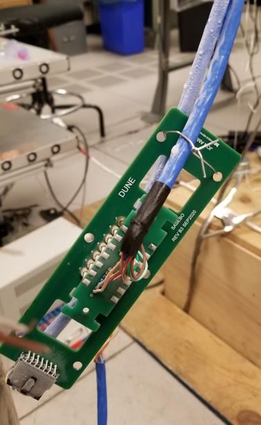
For the Photon Detectors (PD's) can you point us to documentation
which shows how the PD cable is connected to the PD module, how
the particular connector was chosen and how it was cold tested /
stress tested?
●   The PD consortium is responsible for specifying these details of the their
    connectors, and providing the PD hardware (rails and cables). The APA
    consortium is responsible for providing the real estate for the hardware, and
    interfacing with the various mechanical connections to the APA frame.
●   As we saw in Dan’s talk yesterday, the PD cables were installed during the PSL
    cold test of an APA and there were no obvious problems with them
●   We contacted Dave Warner to answer these questions

                                                                                     4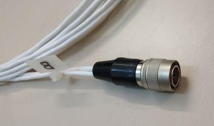
Q2: For the Photon Detectors (PD's) can you point us to
documentation which shows how the PD cable is connected to the PD
module, how the particular connector was chosen and how it was
cold tested / stress tested?

Answer: The connection is described in general in the Photon
Detector Cable Harness Rev. 6.20, which is included in the
PD review documentation package. In general, mill-max pins mounted
to a PCB attached to the PD module automatically mate to the sockets
included in the connector board mounted to the APA during assembly.
Connections went through multiple cryo tests at CSU, at PSL, and in
Milano. See details in following slides.
Cable Harness document EDMS 2383682: https://edms.cern.ch/ui/#!master/navigator/document?P:100255026:100931280:subDocs
PD Review documentation: https://edms.cern.ch/ui/#!master/navigator/project?P:100255026:100931288:subDocs
SASEBO-D1
(Screw and Socket Electrical Board)
                                           PD module connections
Mill-Max Pin Socket
P/N 9837-0-15-80-14-27-10-0

AECB                                                               PD module
(ARAPUCA Electrical and Contact Board)
Mill-Max Pin
P/N 9837-0-15-80-14-27-10-0

n.b.: Relative thermal contraction of
the module relative to the APA is small,
but was addressed in the design.

Thermal contraction and tolerance
buildup are addressed in the PD
structural analysis note (Sec. 3.1)
presented at the PDR (EDMS 2380229).

Module screws to        Connector here
APA Frame here

                                                                        Cold amplifier board
              ~1m                                                       Inside center APA tube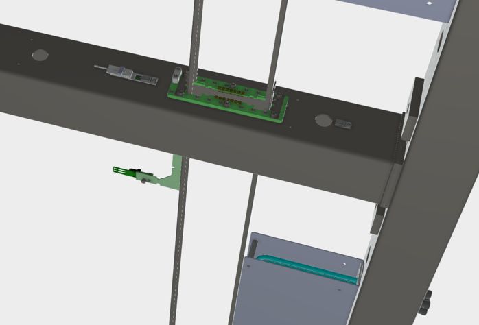
Cryogenic testing
                                                               Readout of a supercell
                                                                     with 35m cable

   Prior to test (Dummy mockup)

                                       Board assembly during
  Tests performed:                     cycling
                                                               Upcoming tests:
  • CSU: Multiple (>20) immersions into LN2, monitoring
    connectivity and high-frequency signal transmission.       • NP-04 cold box test: 2 operational
  • PSL: Cryogenic GN2 test of connector boards and              modules and 8 module frames to be
    module mockup in APA frame (2 cycles).                       tested in the CERN cold box as part of
  • Milano: Demonstrated >4 S/N ratio readout of                 APA test
    supercell through full 35m cable harness including
    connector PCBs.                                            • ProtoDUNE 2
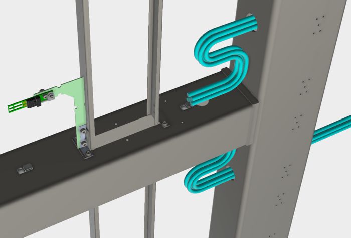
Is there documentation for the tests which were performed at Ash
River? What additional testing remains to be done for the final DUNE
APA design at Ash River and is there any FEM analysis of the final
DUNE design with cables?
●   There was a workshop held at Ash River (09/19) to go through the installation
    process and the result was a summary of lessons learned and a set of
    procedures and other documents, both in EDMS (see linked documents)
●   There are plans to practice manipulating the APAs from the transport frame and
    deploying the different cabling configurations at Ash River
●   Certainly the ProtoDUNE II installation will be another test of the plan and allow for
    testing the trolley, DSS connection, and cabling schemes
●   The cables are included in the model used for analysis
●   There are two talks this morning that will provide more details:
     ○ Dan’s talk on the structural analysis of the APAs
     ○ Tom’s talk on the installation process
                                                                                             5
Can you please point us to the drawings for the cable conduit? We
want to ensure the specification for deburring is called out on the
drawing
● Please see EDMS 2112694, specifically the drawing labeled 8760086_REV_-.pdf
○ This drawing specifies “Break all sharp edges, internal and external”
○ PSL also emphasized with the vendor that the conduit be carefully deburred, and they
did a good job
○ We can add more detail to the deburring note if desired
6During the talks, there was mentioned the process for the local
drawings at PSL being stored on a Solid Works database and then
eventually posted to EDMS. When other production sites (both in the
US and the UK) need drawings, do these come from EDMS or from
the PSL database? If from EDMS, what controls are present to ensure
people are receiving the most recent version?
● EDMS is the source of all drawings for all production sites
● If a drawing is not in EDMS, it is not considered released for use by the
consortium
● We are developing an engineering change request procedure that will have as a
step the posting of any changed drawings on EDMS
● We will use EDMS to track and approve/reject the engineering change requests
● The ongoing construction of APAs at Daresbury, using EDMS, allows to identify
any residual issues and resolve them.aMaking .
7Questions from Second Day
8We wanted to ensure that sufficient detail about the monitoring of the
APA's during shipping was included in Jeff's talk tomorrow, in specific
some of the details about the monitors, requirements, and any interface
between the shipping company and the consortium to make sure the
requirements are met and thus damage to the APA is mitigated.
● Will defer this one until after Jeff’s talk
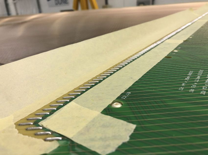
9Could we receive more clarification about what is the standard practice for
soldering the wires in the instance that the wires are above the geometry
board? There wasn't sufficient information available from the one photo
we saw to understand if the spacing that appears to be present is typical
and how it is dealt with during the soldering procedure
● The procedure for soldering the wires is available on EDMS, specifically section
9.2.1 of the file 8760Doc011_Tape_Solder_Trim.pdf
● Prior to soldering the frame supports are adjusted to minimize any frame
distortions that could cause wire to be above the solder pads (section 9.2.1.5)
● The wires are taped to the board before soldering, which provides a mask to
prevent solder splatters on the board and also traps any ends that will eventually
be cut
● Taping also holds the wire against the pad before soldering
10U-layer wires taped during soldering
11The committee was also wondering if any unexplained wire breakage had
been encountered during construction which might suggest defects in the
wires from the manufacturer? If so, we would want to recommend a
"pre-screening" of the wires prior to winding. If no such breakage had
been seen, that would be helpful to know.
● A review of the PSL logs from ProtoDUNE showed there were no instances of
unexplained breakage during construction
● Daresbury also confirms that after winding more than 100 km of wire they have
seen no unexplained breakage
● Any breakage was the result of either tooling or operator actions and no break
suggested a problem with the wire
● A materials certification comes with each order from the vendor
● PSL tested 3 samples from each spool for break strength during ProtoDUNE I and
recorded the values - all were more than 25 N
12You can also read