An Innovative Project of a Bionic Robot for Social Applications in Felinotherapy
←
→
Page content transcription
If your browser does not render page correctly, please read the page content below
Pomiary Automatyka Robotyka, ISSN 1427-9126, R. 25, Nr 4/2021, 5–18, DOI: 10.14313/PAR_242/5

An Innovative Project of a Bionic Robot for Social
Applications in Felinotherapy
Sonia Litwin, Klaudia Woźniak
Politechnika Warszawska, Wydział Elektroniki i Technik Informacyjnych, Instytut Radioelektroniki i Technik Multimedialnych,
ul. Nowowiejska 15/19, 00-665 Warszawa

Mariusz Olszewski
Politechnika Warszawska, Wydział Mechatroniki, Instytut Automatyki i Robotyki,
ul. św. Andrzeja Boboli, 02-525 Warszawa

Abstract: The paper describes an innovative design of a bionic robot for applications in felinotherapy
supporting hospital and home psychotherapeutic treatment of bedridden children and adults. The
project was engineered by biomimicrating a biological cat, reaching its robotic model. Particular
attention in this process was devoted to capturing the essence of feline motorics behavior and the
possibility of mapping them in a mechatronic model. The geometry, kinematics and kinetics of this
model were analyzed, creating assumptions for its practical implementation in the real mechanism of
cat skeleton movement. The used software used the topology of elements in Autodesk Fusion 360
Simulation workspace by performing the critical elements of the mechatronic model in print using SLS
technology. The work was also supported by a graphical simulation in the PyBullet environment.

Keywords: robotics, bionics, biomimicry, felinotherapy, robotic cat, 3D modeling, movement mechanism, geometry, kinematics, kinetics, motor drives

1. Introduction                                                                                                Fig. 1. Half-blood of Maine Coon, one of
                                                                                                               the authors of the article – the geometric
                                                                                                               dimensions of this cat and its motor
Felinotherapy – interchangeably, in rela-                                                                      behavior were used to develop the
tion to cats’ therapy, a term used is                                                                          assumptions and concept of the
                                                                                                               construction of the mechatronic model of
a combination of two words from two
                                                                                                               the mechanism of cat movements
languages: Latin felis – cat and actu-                                                                         Rys. 1. Półkrwi Maine Coon jednej z autorek
ally felino – as an adjective and Greek                                                                        artykułu – rozległości geometryczne tego kota
         , therapeia – care, treatment [1].                                                                    oraz jego zachowania motoryczne posłużyły
One of the methods of using animals in                                                                         do opracowania założeń i koncepcji konstrukcji
                                                                                                               mechatronicznego modelu mechanizmu kocich
psychological treatment, called in English                                                                     ruchów
pettherapy, animaltherapy or also collo-
quially zootherapy. These methods were
initiated and developed by Boris Levin-
son, an American child psychiatrist, in
the years 1958–1964 [5].
   The cat, as a therapeutic element in
the field of pettherapy, was introduced by
the Brazilian doctor Nise de Silva already                                                                 company helps to reduce the feeling of
in the middle of the last century. She sta-                                                                loneliness, depression and stress, incre-
ted [21] that contact with a cat improves our mental and physi-                  ase mobilization to act and undertake various forms of activity
cal condition, even just observing its behavior and being in its                 promoting mental health. Not to mention the analytically deter-
                                                                                 mined stimulation of the human body to secrete endorphins,
                                                                                 lowering blood pressure, the level of triacyglycerol and even cho-
 Autor korespondujący:                                                           lesterol. Also simulate the immune system to function [23, 24].
 Sonia Litwin, sonia.litwin.ibm@gmail.com                                           A significant problem in felinotherapy is the choice of cat
                                                                                 breed. Of the many cat breeds, the Maine Coon breed is espe-
 Artykuł recenzowany                                                             cially predestined here. They are very large cats, up to 40 inches
 nadesłany 14.10.2021 r., przyjęty do druku 02.12.2021 r.                        long, larger than all the others, but very affectionate and socia-
                                                                                 ble, interesting people, especially gentle with children. Due to
                    Zezwala się na korzystanie z artykułu na warunkach           their friendly personality, these beautiful cats are usually refer-
                    licencji Creative Commons Uznanie autorstwa 3.0              red to as gentle giants (Fig. 1) [22].

                                                                                                                                                           5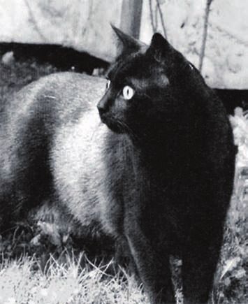
An Innovative Project of a Bionic Robot for Social Applications in Felinotherapy

  Two types of therapeutic programs applying felinotherapy are becoming popular                               2. The challenges of
nowadays [5, 23, 24]:                                                                                            the bionic cat project
− therapy for children with mental disorders – used in cases of autism, ADHD,
  mental retardation, mental illness, Asperger’s syndrome and various emotional                               The first and main challenge of the
  disorders such as shyness, fear of speaking and lack of self-confidence,                                    described project is the cat itself. With
− therapy for the elderly, especially those suffering from depression and under stress.                       its skeletal flexibility and the agility of
  A cat is proposed as a companion in the life of an elderly, lonely, disabled person,                        the muscles of the body, and with all
  motivating him to be active in the form of caring for him, reducing the feeling of                          its wealth of possibilities for movement.
  loneliness. During direct contact with the cat (lifting, stroking and cuddling) the                         Starting with cats’ favorite, frequent
  human muscles heat up (the cat’s body temperature is 38–39 °C), which impro-                                falling asleep in the form of a rolled up
  ves blood circulation and removes the feeling of cold in the feet and hands, relie-                         ball, by immediately waking up from
  ves rheumatic pains, with phlebitis. Cats instinctively look for sore spots on the                          sleep under the influence of a possible
  human body and lay down on them, warming up these places. They have a general                               or existing threat, walking, and usu-
  soothing effect on mood swings and have a relaxing effect on the human psyche.                              ally running, with the phases of con-
                                                                                                              tact (stance) and phases of no contact
   However, felinotherapy cannot be used by people allergic to cat hair, suffering from                       (swing) of the paws with the ground,
ailurophobia, i.e. irrational, beyond reasonable fear of cats and people aggressive                           with excellent climbing skills, even
towards animals, including cats. Also people who require care for their immunity,                             tall trees, to overcome all obstacles.
e.g. in the case of infectious diseases and the use of chemotherapy. The problem is, of                       And falling, even from great heights,
course, the consent of a seriously ill person’s physician or caregiver to the presence of                     always on the (proverbial) four paws.
a live animal in a room, in an intensive medical or inpatient hospital ward, requiring                        And jumps, without a run-up, even
sterilization, decontamination, disinfection, and generally strict antisepsis of the envi-                    6 times the distance of its own length.
ronment. The more so that cats also require systematic care, which can, for under-                            And gentle, unprecedented in compa-
standable reasons, be undertaken only by selected treatment facilities, primarily care                        rison to other domestic animals, pat-
facilities, e.g. orphanages and autumn-life homes.                                                            ting each other with its two front paws,
   These problems prompted the authors to address the problem of building a mecha-                            with a pleasant purr and looking into
tronic cat model that could replace a living soft toy and play the role of a companion                        the eyes of the person with whom the
for children and adults in a hospital, hospitalization or home environment, characteri-                       cat wants to spend a few moments, e.g.
zed by the durability and functionality of robots used today in the manufacturing                             a little nap ... and an observer of the
industry [13, 15].                                                                                            behavior of these lovely animals ...
                                                                                                                 There are works in the field of veteri-
                                                                                                              nary medicine that relate to the mecha-
                                                                                                              nics of cat movement. The simplest
                                                                                                              method of its examination is the use of
                                                                                                              the motion capture system, consisting of
                                                                                                              cameras cooperating with sensors placed
                                                                                                              on the animal’s skin [31]. Cats are encou-
                                                                                                              raged, usually with a tasty reward, to
                                                                                                              walk (run) a designated section of road
                                                                                                              or walk on a treadmill (Fig. 2a). On the
                                                                                                              basis of the collected data, the changes
                                                                                                              in the position of these points in time
                                                                                                              are created for different motor behaviors
                                                                                                              (Fig. 2b, c)
                                                                                                                 An important place in the project
                                                                                                              was taken by the aforementioned Maine

Fig. 2. Representation of the muscle and skeletal model of the cat’s hind limbs: a) the
principle of studying the cat’s gait using motion capture cameras cooperating with
sensors placed on the animal moving on a treadmill [27], b) defined angles of movement
of the skeleton segments of the cat’s hind limbs, c) simplification of the view of the
muscles the cat’s hind limbs defined in the coordinate system placed in the middle of the
drawing [28]
Rys. 2. Reprezentacja modelu mięśniowo-szkieletowego tylnych kończyn kota: a) zasada
badania chodu kota z zastosowaniem kamer motion capture współpracujących z sensorami                    Fig. 3. The first sketch of the Cthulhu2.0 bionic
umieszczonymi na zwierzęciu poruszającym się na bieżni [27], b) zdefiniowane kąty ruchu                 robot model in the project [8]
członów szkieletu tylnych kończyn kota, c) uproszczony zarys widoku mięśni tylnych kończyn              Rys. 3. Pierwszy szkic modelu bionicznego robokota
kota, zdefiniowany w układzie współrzędnym umieszczonym pośrodku rysunku [28]                           Cthulhu2.0 w projekcie [8]

6                       P   O   M   I   A   R   Y   •   A   U   T   O   M   A   T   Y   K   A   •   R     O   B   O   T   Y   K   A              N R 4/ 20 21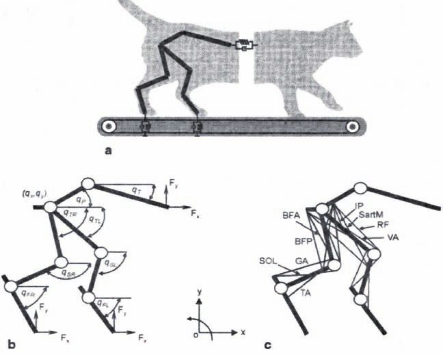
Sonia Litwin, Klaudia Woźniak, Mariusz Olszewski
Coon half-blood (Fig. 1) by one of the authors, serving as a reference model and
a source of initially fantastic design inspirations (Fig. 3). The cat’s name is Cthulhu
(called “ktulu” ...) – it was inspired by a fictional creature from the fantasy novels of
the American writer Howard Philips Lovecraft (1890–1937). Hence the name of the
robot from the described project as the second such fantastic creature, i.e. Cthulhu2.0.
The second challenge of the project was the rapidly growing market of bionic pro-
ducts [3, 6, 11, 19] that is solutions shaped by a form found in nature, but embedded
in the area of influence of various practical and functional requirements related to
mechatronic technology [9, 10]. The first, innovative and technically advanced presen-
tation of bionic solutions related to the developments of Festo AG & KG took place
in 1913 at the Warsaw University of Technology [4, 14].
The boundaries of the aforementioned bionic products market are, on the one hand,
interactive toys for children, and, on the other hand, robotic solutions with dominant
bionic characteristics, with industrial applications already proposed or anticipated in
the near future [16, 17].
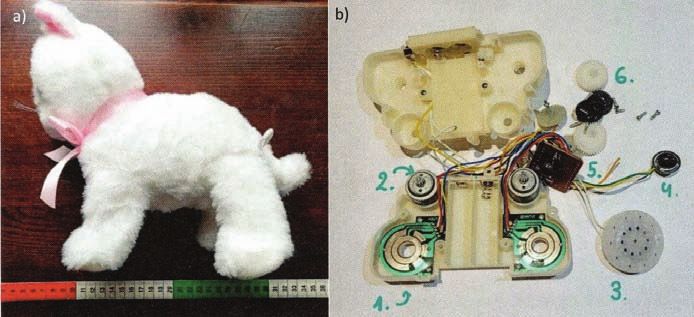
An example of a solution from the first group is an interactive, plush robotic catcher
(Fig. 4), which moves and meows when you press its back or clap its hands. Then one of a)
the 6 sequences of moving the front and hind legs and meowing is activated randomly,
unfortunately very far from what we call a cat meowing or purring.
The second group includes mainly cobots, i.e. cooperative robots, adapted to direct
cooperation with humans (Fig. 5a) and mobile, walking robots (Fig. 5b).
A good example of a collaborative robot is BionicCobot, developed at Festo AG &
KG [13, 15]. The solution was known already in 2017, but still respects the enormity
of the problems that have been successfully solved. The robot’s mechanism and its geo-
metric extensions perfectly meet the ergonomic requirements of the human figure, as
well as its speed, acceleration and load parameters. Its movements can be programmed
in all three ways used in conventional, on- and off-line robotics, and it is particularly
convenient to program by teaching that meets the requirements of collaboration by
guiding the mechanism by hand. This was achieved by the consistent use of a pneumo-
tronic servo drive with vane rotary actuators. Thanks to this, the mechanism is “soft”,
it is smoothly guided by hand, programming of the position and path of movement
is therefore very easy, even in conventional settings of the mechanism that cannot be b)
achieved by robots, e.g. ball, cat, curl (Fig. 5a).
An equally interesting product of this group is OpenDog, a walking robot, an exam- Fig. 5. Contemporary bionic robots:
a) industrial cobot BionicCobot of Festo
ple of the Do It Yourself (DIY) solution, which is becoming more and more popular in
AG & KG with pneumotronic vane servo
the group of people who undertake their own “home” work. In this category, one can motors enabling the bionic twisting-
more and more often meet bionic robots, imitating various animals, even quadrupeds, arranging of the kinematic chain of the
but with quite limited movement mechanisms (Fig. 5b). mechanism [13, 15], b) the OpenDog
The aforementioned necessity to install the Cthulhu2.0 bionic robot in the area of mobile walking robot, designed for
your own amateur 3D printing using
practical requirements related to felinotherapy was another challenge of the described components from hobby stores
project. Used here are both available publication sources, e.g. Fig. 6 [27–29] and Tab. 1 (James Burton) [25]
[30], and above all, own observations of the behavior and activities performed by living Rys. 5. Współczesne roboty bioniczne:
Cthulhu (Fig. 1). Each of these activities was then segmented into individual positions a) kobot przemysłowy BionicCobot holdingu
Festo AG & KG z pneumotronicznymi
analogous to the film frames. On this basis, it was possible to determine the ranges of
serwosiłownikami łopatkowymi
motion of the Cthulhu2.0 model. The following activities were considered important: umożliwiającymi przedstawione na zdjęciu
bioniczne skręcone-ułożenie łańcucha
kinematycznego mechanizmu [13, 15],
b) robot mobilny kroczący OpenDog,
przeznaczony do własnego, amatorskiego
wykonania drukiem 3D z wykorzystaniem
komponentów ze sklepów dla hobbystów
(James Burton) [25]
Fig. 4. Interactive robo-toy for children, Interaktivni kotatko: a) view of the toy, b) mechanism after
disassembly into its components: 1 – drive position sensors, 2 – two electric drive motors,
3 – loudspeaker, 4 – touch sensor, 5 – controller board, 6 – transmission (Fenghua Fun Toys)
Rys. 4. Robo-zabawka interaktywna dla dzieci, Interaktivni kotatko: a) widok zabawki, b) mechanizm po
rozebraniu na części składowe: 1 – sensory pozycji napędu, 2 – dwa elektryczne silniki napędowe,
3 – głośnik, 4 – sensor dotyku, 5 – płytka sterownika, 6 – przekładnie napędowe (Fenghua Fun Toys)
7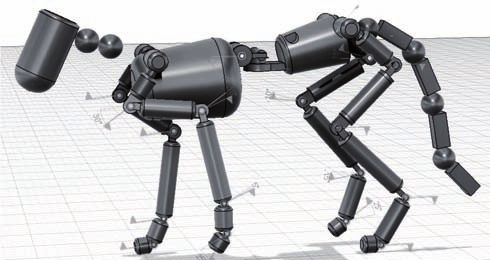
An Innovative Project of a Bionic Robot for Social Applications in Felinotherapy
− Starting Position – a natural position from which it is possi- In addition, each of these activities is to be varied with the
ble to perform any activity, in this position the cat stands tilt of the head or the selected shape of the tail, which will give
still on all four paws, Cthulhu2.0’s behavior even more realism.
− Walk 1 – this is how the slow movement of the cat in the Based on the collected publication data [7, 32] and own
space of the home environment was called (jog), research [8], a model of the robot’s skeleton was created from
− Walk 2 – faster jog observed when calling “Cthulhu” or segments connected by joints with one degree of mobility. The
the cat’s increased interest in elements of the environment, simplified implementation becomes easy to implement, both in
− Jump – a sequence of movement consisting of three pha- simulations and in the later stages of prototyping the Cthulhu2.0
ses, preparation for jump, lift-off and landing phases, the robot mechanism.
jump is made from the lower landing surface to the higher This process was carried out using the anatomical model of
surface target surface, the cat’s skeleton (Fig. 7a), mapping the geometric extensions
− Jump Down – an action similar to Jump, it is also a sequ- of the skeleton segments. Then, the preliminary arrangement of
ence of three phases, but the starting surface is higher than the junction points (JP) where the motion will take place was
the target surface, made. Each segment was approximated in Autodesk Fusion 360
− Sit – the cat moves to a sitting position and remains in Simulation by a solid that corresponds to the volume of the cat’s
a sitting position, dimensions. In this way, a model was created consisting of basic
− Leaving the Sit – leaving the sitting position to the Star- solids connected with each other by means of joints-junction
ting Position, points with a defined mobility value (Fig. 7b).
− Lying Down – the cat moves to this position from the Sit The limbs and parts of the body are shown by chains of solid
down position and remains in this position; Due to the cylinders. The tail was also brought closer with the help of
limited load capacity of Cthulhu2.0 and its weight (approx. solids, but cuboids. On the basis of such a simplification, it was
8 kg), it was decided not to take into account the scenario possible to initially estimate the dimensions and masses of the
of going directly from the Starting Position to the Lying segments needed to start calculating the kinematics and kinetics
activity. The cat’s paws are folded under his body, the tail of the robot’s mechanism. The masses were estimated by defin-
is curled around, ing the material from which the element will be made with the
− Exit from Lying Down – leaving the Lying Down position use of AF360 Simulation. At this stage, it was already assumed
to the Start Position. that the mechanism would be made in 3D printing technology,
so it was assumed that the segments would be made of resin
with different values of mechanical strength.
In order to compare the effects that can be achieved with
computer graphics programs with engineering programs such
Fig. 6. Traffic analysis charts of a cat during a walk: A) movement as AF360 Simulation, a simulation-animation of the robot’s
relative to the hip joint, B) change the angle value between the skeleton motion was run in the Blender environment, using the
limb segments, C) changing the length and position of the limb, developed skeleton model. Blender introduces “bones” that ani-
D) changing the angles in the individual joints – on the right drawing:
show motion simulation rear limb cat, contact phases of paws with
mate the movement of the robot’s skeleton. An already deve-
the ground (stance) and the phases of lack of contact of paws with loped model was not used because the Blender environment was
a substrate (swing) [27, 29] found to allow for better animations of the anatomical structure.
Rys. 6. Wykresy analizy ruchu tylnej kończyny kota podczas chodu: With the help of the script, the model created in AF360 Sim-
A) ruch względem stawu biodrowego, B) zmiana wartości kąta pomiędzy
ulation was imported into the PyBullet environment. This pro-
członami kończyny, C) zmiana długości i położenia kończyny, D) zmiana
wartości kątów w poszczególnych stawach kończyny – po prawej rysunku: gram has the potential to transform animated motion into robot
przedstawienie symulacji ruchu tylnej kończyny kota, fazy kontaktu łapy movements using the Robot Operating System (ROS) platform.
z podłożem (stance) i fazy braku kontaktu łapy z podłożem (swing) [27, 29] It also supports the kinematic and kinetic analysis of the model
A movement relative to hip joint B limb segments
hip TS DS
0
50
movement
y position mm
1 high
angles dag
–50
4 5 A
knee root
6 PoR
0
2
A
Hip
–100 –50
3
ankle A
–150
Knee
Ankle
–100 0 50 0 10 20 30 40
x position mm time
C D
limb length and orientation joint angles
40
FS BS F E1 E2 E3
150
length and angle
orientation
20
angles dag
50 100
L lenght
0
–40
Stance Swing Stance
0
0 10 20 30 40 0 10 20 30 40
time time Gaid locomotion
8 P O M I A R Y • A U T O M A T Y K A • R O B O T Y K A N R 4/ 20 21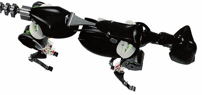
Sonia Litwin, Klaudia Woźniak, Mariusz Olszewski

Tab. 1. Movement ranges of domestic cat joints according to [30]                                     Another, already constructive, assump-
Tab. 1. Zakresy ruchu stawów kota domowego wg [30]                                                tion of the Cthulhu2.0 project, as an
                                                                                                  imitation of a cat, was to adopt the fol-
                                                                                                  lowing conditions for the construction of
                                                                                                  its mechanism:
                                                                                                  − two front and two hind limbs of
                                                                                                      Cthulhu2.0 are treated as mir-
                                                                                                      ror images,
                                                                                                  − these limbs, imitating the anatom-
                                                                                                      ical structure of the cat’s skeleton
                                                                                                      (Fig. 7a), are kinematically com-
                                                                                                      posed of a chain of two groups of
                                                                                                      segments {CR, BR1, BR2, BR3, BL1} for
                                                                                                      the above-mentioned shoulder-blade,
                                                                                                      shoulder, arm, forearm and wrist, and
                                                                                                      the segment feet {BL2}. This struc-
                                                                                                      ture provides 5 degrees of limb mobil-
                                                                                                      ity, treating the cat’s foot member as
                                                                                                      a robot tool (Fig. 7b),
                                                                                                  − at the point of connection of seg-
                                                                                                      ments (joints in a cat), tension
                                                                                                      mechanisms are to be used (Fig. 8),
mechanics and allows you to check the operation of the robot skeleton under force,                    which allows to avoid the so-called
moment and gravity loads in a virtual environment.                                                    offsets of electric drive motors, dis-
                                                                                                      torting the imitation of anatomical
                                                                                                      joints and allowing the most faith-
3. Assumptions of the bionic cat project                                                              ful representation of the cat’s ana-
                                                                                                      tomy in the model. The transmission
A safe, defined by the standards Men-Robots-Collaboration (MRC) [13], functional                      of the drive through the tendons also
cooperation of the Cthulhu2.0 robot with people who passively and actively use                        allows the motors to be placed close
felinotherapy was established – the following kinematic and load limitations were                     to the model body [20]. It is impor-
adopted:                                                                                              tant because the work of the mecha-
− for the speed of rotational (angular) movements of the paws – the maximum                           nism depends to a large extent on the
    value for the individual five parts of the cat’s paws, the same for the front and                 weight distribution, the lower mass
    hind legs, is 500°/s, 750°/s, 590°/s, 1.2°/s, 1.6°/s (from shoulder-blade, shoulder,              of the limbs means their lower iner-
    arm, forearm to wrist). These are the maximum values that can also be safely                      tia and better dynamics of movement,
    achieved by Cthulhu2.0 limbs,                                                                 − it was assumed that the gears were
− for the speed of linear movements of the cat’s front and hind legs – resulting from                 not used in the drives of the CR
    the above-mentioned values of rotational movement and the geometric extent                        and BR1 segments (the cat’s shoul-
    (length) of the paw segments – its maximum value for Cthulhu2.0 limbs cannot                      der-blade and shoulder), which
    exceed 1 m/s,                                                                                     ensures a reduction in the volume
− for the mass of the mechanism – the value of the mass of the Cthulhu2.0 mech-                       of the structure in this part of the
    anism was assumed to be close to the mass of the cat, here the assumption was                     Cthulhu2.0 mechanism – it was
    a comparable size – geometrical extent of the robot and the size of the reference                 inspired by the construction of
    Maine Coon cat (Fig. 1),                                                                          a walking robot designed by MIT
− for the mass load of the mechanism – it was assumed that the maximum external                       Biomechanics Robotics Lab. Resig-
    mass load of each Cthulhu2.0 limb may not exceed 1 kg.

a)                                                                         b)

Fig. 7. The stage of simplifying the cat’s skeleton for the development of a bionic model: a) anatomical model of the domestic cat skeleton
[26], b) visualization of the simplified kinematic scheme of the Cthulhu2.0 robot mechanism developed in the Autodesk Fusion 360 Simulation
environment: 22 ponds joints-points of connection (JP) are marked with a flag, segments of the mechanism made of solid basic – cylinders and
cuboids
Rys. 7. Etap uproszczenia szkieletu kota dla opracowania modelu bionicznego: a) anatomiczny model szkieletu kota domowego [26], b) wizualizacja
uproszczonego schematu kinematycznego mechanizmu robokota Cthulhu2.0 opracowana w środowisku Autodesk Fusion 360 Simulation: 22 stawy-punkty
złączenia (JP) oznakowano flagą, człony mechanizmu wykonano z brył podstawowych – walców i prostopadłościanów

                                                                                                                                              9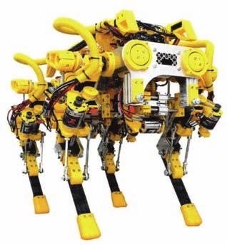
An Innovative Project of a Bionic Robot for Social Applications in Felinotherapy

Fig. 8. Linkage mechanism for Cthulhu2.0 [20] – external view
Rys. 8. Mechanizm cięgnowy [20] połączeń mechanizmu Cthulhu2.0 –
widok od zewnątrz

  nation from the toothed belt transmission also reduces the                    Fig 9. The final model of the bionic Cthulhu2.0 robot in the project [8],
  failure rate of this structure,                                               visualization made in Autodesk Fusion 360 Simulation, view from the
                                                                                left side in profile – visible movement joints of the joints-segments,
− it was assumed that the drive motors were placed as the
                                                                                made as tension mechanisms. The light color marks the casing
  heaviest components of the mechanism, as close to the robo-                   segments of the mechanism made of Draft resin, the dark color –
  t’s mass center as possible – it improves the stability of the                operating under load, made of Clear resin
  movement of the entire mechanism,                                             Rys. 9. Finalny model bionicznego robokota Cthulhu2.0 w projekcie [8],
− flexible, even if it is implemented to a limited extent, the                  wizualizacja wykonana w Autodesk Fusion 360 Simulation, widok ze strony
                                                                                lewej z profilu – widoczne połączenia ruchowe członów – stawy, wykonane
  construction of the spine and tail of the Cthulhu2.0 mecha-                   jako mechnizmy cięgnowe. Kolorem jasnym oznaczono człony osłonowe
  nism was also adopted – this has a positive effect on the                     mechanizmu wykonane z żywicy Draft, kolorem ciemnym – działające pod
  speed and naturalness of gait achieved by walking robots                      obciążeniem, wykonane z żywicy Clear
  – this was confirmed by the study of the motor activity of
  quadrupeds with a cheetah-like structure. The tail also acts
  as a counterweight to the robot’s head, in which it is plan-
  ned to place electronics that load it by gravity,
− the center of mass of the mechanism was planned to be pla-
  ced in the geometrical center of the structure. This adop-
  tion allows the weight of the robot to be evenly distributed
  among the four limbs, relieving the drives and preventing
  them from overheating.

4. Selected fragments of the description of
   the construction and implementation
   of the bionic cat project
The elements of the Cthulhu2.0 model developed in the pro-
ject (Fig. 9) were made thanks to the courtesy of the Festo
Polska Application Center, which provided technically advan-
                                                                                Fig. 10. Printed from Standard Clear Formlabs resin Cthulhu2.0 robot
ced Formlabs form 2 printers. For 3D printing in the SLA                        “tail” segment
technology, a liquid, laser-hardened photopolymer resin was                     Rys. 10. Wydrukowany z żywicy Standard Clear Formlabs człon „ogona”
used. Standard Draft resin non-load bearing elements, e.g.,                     robokota Cthulhu2.0
anti-damage guards, are light colored in Fig. 9, and weighted
components are made of Clear resin for smooth, accurate and                     in AF 360 Simulation. Based on the original shape and input
high-strength printing – dark colored. This material is used for                parameters in the form of loads, the simulation calculates how
making joints and more important joints of the mechanism.                       much material can be removed without affecting the mechanical
   The predominance of light color in Fig. 9 is due to the desire               strength of the element.
to present cable mechanisms ensuring movement in the connec-                       It was assumed that the center of mass and also the geometric
tions of the segments of the robot mechanism.                                   center of the robot, similarly to the anatomical cat, is located
   Before printing, all elements were optimized in the PreForm                  in the chest, behind the line of the front paws. This feature will
software dedicated to Form 2 printers (Fig. 10). The largest                    allow the cat’s weight to be evenly distributed between the four
printable dimension was 17.5 cm. This means that it was nec-                    paws and four limbs of the robot, relieving the drive motors and
essary to split some parts of the model and design them in two                  preventing them from overheating.
parts printed separately.                                                          It was also assumed that the trajectory of movement of each
   The weight of the robot model has a decisive influence on                    limb of Cthulhu2.0 is determined by the Tool Center Point
the engine load, and thus on the dynamics of the mechanism.                     (TCP), suspended at the end of the BL1 segment, at the junction
The easiest way to reduce its value was to remove unnecessary                   with the BL2 (foot) segment. This location was chosen because
material from its constituent elements. This goal was achieved                  the cat, while walking, in this place (point) exerts the greatest
by two methods. The first was “manual optimization” when                        pressure on the ground.
designing the mechanism, the second was the method of using                        The CR segment (equivalent to a cat’s shoulder-blade) is
the simulation tool and automatic shape optimization available                  responsible for the adduction and abduction movement of a limb

10                      P   O   M   I   A   R   Y   •   A   U   T   O   M   A    T   Y   K   A   •   R   O   B   O   T   Y   K   A             N R 4/ 20 21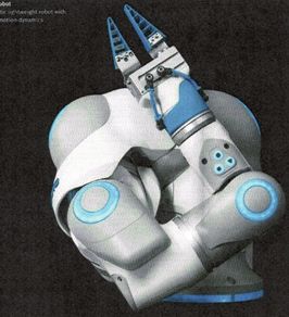
Sonia Litwin, Klaudia Woźniak, Mariusz Olszewski

(cat’s paw). Its main element is an engine with a cover. This                 to which the strands are attached. One end of the string is
segment is attached directly to the body. Similar to the cat’s                turned on the spool clockwise, the other end clockwise. The
scapula it is angled from the vertical axis. The consequence of               direction of the motor’s movement is responsible for win-
such a construction is also an inclined trajectory, along which               ding and unscrewing the bobbin. In this way, the tendons
the limb is abducted. This action is intentional as it makes                  responsible for bending and extending the elbow connection
the movement more “anatomical”. The segment can deflect the                   are antagonistically tightened and loosened. This mecha-
shoulder-blade limb Cthulhu2.0 upwards from the starting posi-                nism (Fig. 8) was developed on the basis of the solution
tion up to an angle of 80° with respect to the robot body and                 proposed in the LIMS2 walking robot [18],
30° inwards under the robotic cat body.                                     − a motor with lower energy efficiency, with an identical
   The BR1 segment is placed on the preceding CR segment                      belt-toothed transmission, similarly drives the movement
without the use of a reduction gear (ratio 1:1), directly on                  in a joint-joint connecting the BR3 segment (equivalent to
the axis passing through the center of the drive motor. It is                 a cat’s forearm) with the BL1 segment (equivalent to a cat’s
the equivalent of a cat’s shoulder, it is responsible for the for-            wrist). The tendons with which it moves are threaded thro-
ward and backward movement in relation to the robot’s body.                   ugh the center of the elbow joint from the inside (Fig. 12a).
Together with the CR element, it forms a substitute for the “ball             Such a construction is possible thanks to the tangency of
joint” and completes the range of motion of the cat’s anatom-                 two circles forming the halves of the pond. These circles,
ical structure. Its structure is similar to the CR segment. Its               moving in relation to each other, remain at a constant
main components are the engine and its cover. The axis passing                distance of 2r (r radius of the circle). Therefore, the tendons
through the center of this segment coincides with the axis of                 do not change their length and the movement of the “elbow
the shoulder-blade joint. The range of motion is 100 degrees                  joint” does not affect the movement of the joint following it.
forward and 80 degrees backward, respectively, relative to the
robot body, referring to the vertical axis of the base system.                 The above-mentioned segments CR, BR1, BR2 and BR3 are, refer-
   The BR2 segment (equivalent to a cat’s arm) is connected to the          ring to the construction of industrial robots with a conventional
BR1 segment (equivalent to a cat’s shoulder) also without using             chain structure, segments of the regional part positioning the
a reduction gear. However, it houses two of the three motors                robot effector in the working space. The consecutive parts of this
responsible for the operation of the cable mechanism (Fig. 11):             structure are the local part, orienting the position of the effector
− a motor with greater energy efficiency drives the movement                [12, 13, 15]. In the case of Cthulhu2.0, these are two parts, the
   in the elbow joint through a 6 mm wide belt and toothed                  equivalents of the wrist and foot of the cat’s paw, in the robot’s
   gear with a 3:1 gear ratio. The gear belt moves the spool                mechanism marked as BL1 and BL2.

Fig. 11. Visualization of the “elbow joint” of the Cthulhu2.0 limb: view
of the routing of the tendons from the outside, the dark color marks
the tendon currently wound on the shaft of the motor located in the         Fig. 13. View of the construction of the connection of the segments
preceding segment to the driven one – external view without tendons         BR3 and BL1 of the Cthulhu2.0, the external elements (darker) allow
in Fig. 8                                                                   the tendons to be pulled to the next joint-joint, the internal elements
Rys. 11. Wizualizacja „stawu łokciowego” kończyny Cthulhu2.0: widok         (lighter) allow the tendons to move this joint
prowadzenia cięgien od strony zewnętrznej, ciemnym kolorem oznaczono        Rys. 13. Widok konstrukcji połączenia członów BR3 i BL1 robokota
cięgno aktualnie nawijane na wałek silnika położonego w członie             Cthulhu 2.0, elementy zewnętrzne (ciemniejsze) umożliwiają przeciągnięcie
poprzedzającym do napędzanego – widok od strony zewnętrznej, bez            cięgien do następnego połączenia-stawu, elementy wewnętrzne
cięgien, Rys. 8                                                             (jaśniejsze) umożliwiają cięgnom poruszanie tym połączeniem-stawem

a)                                                                                               b)
Fig. 12. Visualization of the elbow joint of the Cthulhu2.0 limb: a) view of the routing of the tendons from the inside, the shown tendons do not
affect the movement of the joint, they run to the next joint, b) view from the inside
Rys. 12. Wizualizacja stawu łokciowego kończyny Cthulhu2.0: a) widok prowadzenia cięgien od strony wewnętrznej, pokazane cięgna nie mają wpływu na
ruch stawu, biegną one do stawu następnego, b) widok od strony wewnętrznej

                                                                                                                                                   11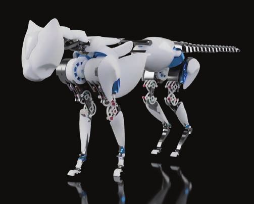
An Innovative Project of a Bionic Robot for Social Applications in Felinotherapy

   These two segments, which form the                  of the elbow joint. However, this joint is much smaller, so in order to strengthen it,
local part of the robot, are an unusual                two interlocking coaxial toothed rollers have been added.
solution and directly mimic the cat’s                     BL1 is the only segment that differs in structure in the fore and hind limbs of
anatomy. In the design of most existing                Cthulhu 2.0. In the forelimb, it is shorter and allows the mechanism to slide and grasp
quadrupeds, these segments are replaced                objects a bit like the middle part of a human hand. As a hind limb, it is about three
with a flexible tip of oval shape, allowing            times longer and is used for stabilization, similar to the foot. It ends with a joint-joint,
movement on most surfaces. This simpli-                which is moved by the longest strands in the robot’s mechanism.
fies the design and control of the motors,                The BL2 segment kitty foot (or sole ...), anatomically the cat’s toes, has been treated
which works well when the main task of                 in this design as a tool at the end of the kinematic chain of the Cthulhu2.0 limb, imi-
the robot is just walking. When designing              tating a cat’s paw (Fig. 14). This made it possible to organize the calculations of kine-
the Cthulhu2.0, however, they wanted to                matics and kinetics and to describe the kinematic structure of the kinematic chains
give it orientation possibilities, enabling,           of the robot’s limbs, similar to the kinematic mechanism of an industrial robot. In
for example, a lateral hitting of a ball               the future, it will also allow to describe the so-called approach vector, that is, it will
with a paw, so these two additional ele-               enable a strong orientation of this cat’s feet. At the bottom of the paw/foot shown in
ments were introduced.                                 Fig. 15, there is a recess in which a silicone cushion for cushioning the robot’s gait
   The rods responsible for the movement               will be placed (Fig. 15).
of these two robotic cat segments are                     During its behavior, the cat’s tail balances the remaining ones, i.e. the function of
pulled through the BR3 segment. It also                a counterweight. However, observing these behaviors of a living Cthulhu, one gets the
houses the motor driving the BL2 compo-                impression that the tail is a separate “entity”, moving independently of the rest of the
nent (3:1 gear). It is connected with the              cat body. When designing the tail for the Cthulhu2.0 it was assumed with minimum
local part by a joint structure with the               requirements, it must have only two sections, each of which can bend completely inde-
principle of operation analogous to that               pendently. Each section requires the use of two motors and two pairs of cables respon-
                                                       sible for its movement, e.g. the proverbial cat’s tail bend. In total, therefore, 4 motors
                                                       and 4 pairs of cables are required.
                                                          The tail, however, is mainly an aesthetic element of the Cthulhu2.0 robot and does
                                                       not carry loads. Therefore, it was planned to use low-power engines to drive it, selected
                                                       so as not to increase the weight of the robot too much (Fig. 16).
                                                          The body of the robotic cat is the attachment point of the first segments of the four
                                                       chain mechanisms of the paw-limbs, as well as the tail and head (Fig. 15). It is treated
                                                       kinematically as the grounded “0” point of the coordinate system in which recursively
                                                       kinematic and kinetic analyzes of the motor behavior of the listed components are
                                                       carried out (Chapter 5). It has been designed so that it is possible to place the driving
                                                       electrics and electronics controlling the model in it.
                                                          The “chest” and “pelvis” of the skeleton of are connected by a mechanism ensuring
                                                       bending in two planes and rotation. Initially, it was planned to use a cable mechanism
                                                       composed of three segments. This mechanism turned out to be not very stable, it
Fig. 14. Connection-joint of the local
segments BL1 and BL2 of the Cthulhu2.0
limb mechanism, driven by tendons drawn
through the previous connection
Rys. 14. Połączenie-staw członów lokalnych
BL1 i BL2 mechanizmu kończyny Cthulhu2.0,
napędzany cięgnami przeciągniętymi przez
poprzednie połączenie

                                                       Fig. 16. Cthulhu2.0 robot tail: visualization of the model ready for 3D printing
                                                       Rys. 16. Ogon robokota Cthulhu2.0: wizualizacja modelu gotowego do druku 3D

a)                                    b)
Fig. 15. “Cat’s feet” looking at them from the
side (a) and partially at the rear (b), visible
recess intended for a silicone cushion
that cushions the robot’s gait, also visible
position of two connections-joints of local
part segments BL1 and BL2, Fig. 13 and 14
Rys. 15. „Kocie łapki” patrząc na nie z boku           Fig. 17. The body of the final model of the bionic robot Cthulhu2.0 in the project [8],
(a) i częściowo z tyłu (b), widoczne wgłębienie        visualization made in Autodesk Fusion 360 Simulation, view of the model from the top,
przeznaczone na sylikonową poduszeczkę                 a proposal for a solution for the moving “spine” of the robot visible
amortyzująca chód robokota, widoczne także             Rys. 17. Korpus ciała finalnego modelu bionicznego robokota Cthulhu2.0 w projekcie [8], wizualizacja
położenie dwóch połączeń-stawów członów                wykonana w Autodesk Fusion 360 Simulation, widok na model od góry, widoczna propozycja
części lokalnej BL1 i BL2, Rys. 13 i 14                rozwiązania ruchomego „kręgosłupa” robokota

12                        P   O   M    I   A   R   Y   •   A   U   T   O   M   A   T   Y   K   A   •   R   O   B   O   T   Y   K   A              N R 4/ 20 21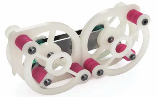
Sonia Litwin, Klaudia Woźniak, Mariusz Olszewski
was replaced with the solution shown in Fig. 17. This solution In order to simplify the calculations, without generating too
does not allow the robot to adopt such cat poses as the afore- much impact on the final results, the geometry of each segment
mentioned bent “cat’s back”. However, it is a good compromise of cat legs was approximated by a cylinder whose length corre-
between the cable mechanism and the complete lack of move- sponds to the geometric extent of this segment, while the radius
ment inside the body, most often found in other walking robots and mass were determined on the basis of the 3D Cthulhu2.0
(quadropeds). model (Figs. 7, 9 and 17).
Out of all the robot components developed in the project [8], It was decided to apply for this analysis a recursive analysis
the “spine” mechanism was subjected to the smallest number of method perfectly embedded in engineering practice, adapted to
iterations optimizing its structure topologically and aesthetically. the calculations of industrial robot mechanisms, taught at the
The last of the Cthulhu2.0 components presented is the “cat’s Faculty of Mechatronics of the Warsaw University of Technol-
head”, the most difficult element in the field of aesthetics, and at ogy to students of Robotics specialization [15]. This method fits
the same time the most demanding in terms of the realization perfectly into the chains of limbs of the designed robot, which
of felinotherapeutic benefits that the robocat is to provide. The are its main subject [8].
“head” was attached to the body by means of a joint-joint made Due to the limited volume of the article, it was unfortunately
of two spheres tangent with each other. Provides ±90° mobility impossible to provide a full analysis. Therefore, it was decided
of the head swinging. It was also possible to add a universal to present only two motors selected for the initial model ver-
rotary joint to this structure, running along its own structural sion of Cthulhu2.0 and to present the possibility of realizing the
axis. This space, however, is intended to accommodate the pro- maximum values of moment loads resulting from the recursive
cessor controller and its cabling as well as the drive and move- method of their calculation described below. Readers interested
ment of the “cat’s eyes and eyelids”. in the extensively complete analysis are referred to the project
[8], available at the Central Library of the Warsaw University
of Technology.
5. Kinematics, kinetics and choice of The following recursive relationships, divided into kinematic
bionic cat design mechanism drives and kinetic analysis tasks, were used in the descriped project of
Cthulhu2.0 model, respectively:
The aim of the kinematic and kinetic analysis of the − for kinematic behavior:
Cthulhu 2.0 robot mechanism was to verify the correctness of − the angular velocity of the analyzed segment i in the
the design and to select the appropriate drive motors. On the machine system i of its coordinates
basis of the assumed initial parameters of the project, inclu-
ding parameters with constant values, such as, for example, ωi / i = Ai / i −1 ωi −1/ i −1 + φiezi −1/ i −1 , (5.1)
the geometric extent of individual segments of the mecha-
nism, their masses and shapes, and parameters with maximum where: Ai/i–1 – transformation matrix of the coordinate
values, such as velocity and angular accelerations, the forces system of the segment i–1 preceding the analyzed seg-
and moments acting were calculated on individual segments, ment into the coordinate system of the analyzed segment
at their selected points (Fig. 18). i; wi–1/i–1 – angular velocity of the i–1 segment, preceding
the analyzed segment, in the i–1 segment system; fi –
assumed maximum angular velocity of the analyzed seg-
ment i; ezi–1/i–1 – the unit vector z from the segment i–1,
preceding the analyzed segment i, in the coordinate system
of the segment i–1,
− the ex-vector matrix of the velocity of the segment i–1,
preceding the analyzed segment i, in the coordinate sys-
tem of the segment i–1
0 −ωi −1,zi −1 ωi −1,yi −1
Wi −1/ i −1 = ωi −1,zi −1 0 −ωi −1,xi −1 , (5.2)
−ωi −1,yi −1 ωi −1,xi −1 0
where: wi–1/xi–1 – x component of the angular velocity of
the segment i–1, preceding the analyzed segment i, in the
coordinate system of the segment i–1; wi–1/yi–1 – y compo-
nent of the angular velocity of the segment i–1, preceding
the analyzed segment i, in the coordinate system of the
Fig. 18. Simplified, for the needs of kinematic and kinetic analysis and segment i–1; wi–1/zi–1 – z component of the angular velocity
the selection of drives, diagram of the mechanism of the forelimbs of the segment i–1, preceding the analyzed segment i, in
of the Cthulhu2.0 robot bionic model, with five degrees of mobility: the coordinate system of the segment i–1;
upper row of markings, CR , BR1, BR2, BR3, BL – counterparts, shoulder
blade, shoulder, arm, forearm and wrist of the cat’s front paw; middle
− the angular acceleration of the analyzed segment i in the
row of markings – machine coordinates setting the movement of machine system i of its coordinates
the robot’s mechanism segments; lower order of markings – machine
coordinate systems, embedded in the descenting points of individual
segments of the robot’s limb mechanism
( )
εi / i = Ai / i −1 εi −1/ i −1 + φiei −1/ i −1 + Wi −1/ i −1 φiezi −1/ i −1 , (5.3)
Rys. 18. Uproszczony, dla potrzeb analizy kinematycznej, kinetycznej
i doboru napędów, schemat mechanizmu przednich kończyn modelu where: Ai,i–1 – transformation matrix of the coordinate
bionicznego robota Cthulhu 2.0, o pięciu stopniach ruchliwości: górny system of the segment i–1 preceding the analyzed segment
rząd oznaczeń, człony CR, BR1, BR2, BR3, BL – odpowiedniki łopatki, barku, i, relationship (5.1); εi–1/i–1 – angular acceleration of the
ramienia, przedramienia i kiści przedniej łapy kota; środkowy rząd i–1 segment, preceding the analyzed segment, in the i–1
oznaczeń – współrzędne maszynowe zadające ruch członów mechanizmu – assumed maximum angular accel-
robokota; dolny rząd oznaczeń – maszynowe układy współrzędnych,
segment system; φ i
osadzone w punktach schodzących poszczególnych członów mechanizmu eration of the analyzed segment i; φi – assumed maxi-
kończyny robokota mum angular velocity of the analyzed segment I;
13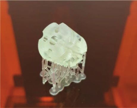
An Innovative Project of a Bionic Robot for Social Applications in Felinotherapy
Wi–1/i–1 – ex-vector matrix of the velocity of the segment analyzed segment i, relationship (5.7); Wi/iWi/i – square
i–1, relationship (5.2); ezi–1/i–1 – the unit vector z from the of the ex-vector velocity matrix of the analyzed segment
segment i–1, preceding the analyzed segment i, in the i, relationship (5.6); r0i,0i–1/i – the geometric extent in the
coordinate system of the segment i–1, coordinate system of the segment i, between the ascending
− the ex-vector matrix of the velocity of the analyzed seg- and descending points of the analyzed segment i,
ment i, in the machine coordinate system of the segment i − the linear velocity of the center of mass point Cmi in the
analyzed segment i, in the coordinate system of this
0 −ωi ,zi ωi ,yi segment
Wi / i = ωi ,zi 0 −ωi ,xi , (5.4) υCmi / i = υ0i / i + Wi / i rCmi ,0i / i , (5.9)
−ωi ,yi ωi ,xi 0
where: u0i/i – linear velocity of the descending point of the
where: wi,xi – x component of the angular velocity of the analyzed term i, relationship (5.5); Wi/i – ex-vector matrix
analyzed segment i, in the coordinate system of the seg- of the velocity of the analyzed segment i, relationship
ment i; wi,yi – y component of the angular velocity of (5.4); rCmi,0i/i – the geometric extent between the center of
the analyzed segment i, in the coordinate system of the mass of the analyzed segment i and the descending point
segment i; wi,zi – z component of the angular velocity of of the analyzed segment i, compare relationship (5.8),
the analyzed segment i, in the coordinate system of the − the linear acceleration of the center of mass point Cmi
segment i; in the analyzed segment i, in the coordinate system of
− the linear velocity of the 0i descending point of the ana- this segment
lyzed segment i, in the machine system i of its coordi-
nates aCmi / i = a0i / i + Ei / i rCmi ,0i / i + Wi / iWi / i rCmi ,0i / i , (5.10)
υ0i / i = Ai / i −1υ0i −1/ i −1 + Wi / i r0i ,0i −1/ i , (5.5)
where: a0i/i – linear acceleration of the descending point
where: Ai,i–1 – transformation matrix of the coordinate of the analyzed term i, relationship (5.8); Ei/i – ex-vector
system of the segment i–1 preceding the analyzed seg- matrix of the velocity of the analyzed segment i, rela-
ment i, relationship (5.1); u0i–1/i–1 – linear velocity of the tionship (5.7); Wi/iWi/i – square of the ex-vector velocity
0i–1 descending point of the segment i–1, in the machine matrix of the analyzed segment i, relationship (5.6); rCmi,0i/i
system i of its coordinates; Wi/i ex-vector matrix of the – the geometric extent between the center of mass of the
velocity of the analyzed segment i, relationship (5.4); analyzed segment i and the descending point of the ana-
r0i,0i–1/i – the geometrical extent of the segment i (the dis- lyzed segment i, compare relationship (5.9),
tance between the segment’s ascending and descending − for kinetic behavior:
points), in its machine coordinate system, − inertia tensor of the analyzed segment i in the coordi-
− the square of the ex-vector velocity matrix Wi/i Wi/i, nate system of this segment, with respect to the center
relationship (5.4), of the analyzed segment i of mass point Cmi
(
− ωi2,yi + ωi2,zi ) ωi ,xi ωi ,yi ωi ,xi ωi ,zi
ΠiC/mi
I xi
−I xyi −I xzi
−I yzi , (5.11)
i = −I yxi I yi
Wi / iWi / i = ωi ,yi ωi ,xi
(
− ωi2,zi + ωi2,xi ) −ωi −1,xi −1 ,
−I zxi
−I zyi I zi
ω ω
i ,zi i ,xi ωi ,zi ωi ,yi (
− ωi2,xi + ωi2,yi )
with Ixi, Ixyi, Iyzi as moments of inertia of the analyzed seg-
ment i in relation to the x axis; y axis; and z axis; Ixyi, Iyzi,
(5.6) Ixzi, Iyxi, Izyi, Izxi – as moments of deviation of the analyzed
segment i in relation to the appropriate pairs of the x axis,
− the ex-vector matrix of the acceleration of the analy- y axis and z axis,
zed segment i, in the machine coordinate system of this − the force acting on the segment i, coming from the seg-
segment ment i+1, leading the analyzed segment i, transmitted
0 − εi ,zi εi ,yi to the segment preceding i–1 (hypothetically the segment
Ei / i = εi ,zi 0 − εi ,xi , (5.7) driving the analyzed segment i), in the coordinate system
− εi ,yi εi ,xi 0 of the analyzed segment i
where: εi,xi – x component of the angular acceleration of Fi ,i −1/ i = Fi +1,i / i + miacmi / i − mi gi / i , (5.12)
the analyzed segment i, in the coordinate system of this
segment; εi,yi – y component of the angular acceleration of where: Fi+1,i/i – the balancing force in the analyzed segment
the analyzed segment i, in the coordinate system of this i the force acting from the leading segment i+1, in the
segment; εi,zi – z component of the angular acceleration coordinate system of the segment i; mi – mass of the ana-
of the analyzed segment i, in the coordinate system of lyzed segment i; acmi/i – linear acceleration of the center of
this segment, mass of the analyzed segment i in this coordinate system,
− the linear acceleration of the 0i descending point of the relationship (5.10); gi/i – the gravitational acceleration act-
analyzed segment i, in the machine system i of its coor- ing on the analyzed segment i in this coordinate system,
dinates − spiral of the analyzed segment i, in this coordinate sys-
a0i / i = Ai / i −1a0i −1/ i −1 + Ei / i r0i ,0i −1/ i + Wi / iWi / i r0i ,0i −1/ i , (5.8) tem, in relation to the point of its center of mass Cmi
where: Ai,i–1 – transformation matrix of the coordinate
system of the segment i–1 preceding the analyzed seg- K iC/mii = ΠiC/mii ωi / i , (5.13)
ment i, relationship (5.1); a0i–1/i–1 – linear acceleration of
C
the descending point of the segment i–1, preceding the gdzie: Πi /mii – the inertia tensor of the analyzed segment
analyzed segment in the coordinate system of the seg- i in this coordinate system, with respect to the center of
ment i–1; Ei/i – ex-vector matrix of acceleration of the mass point Cmi, relationship (5.11); wi/i – angular velocity
14 P O M I A R Y • A U T O M A T Y K A • R O B O T Y K A N R 4/ 20 21Sonia Litwin, Klaudia Woźniak, Mariusz Olszewski
of the analyzed segment i in this coordinate system, rela- coming from the acting forces and moments in the mechanism,
tionship (5.1), and the moment coming from the motor working in the analyzed
− eulerian of the analyzed segment i in this coordinate sys- segment, which drives the next, following the analyzed, segment
tem, with respect to the point of its center of mass Cmi of the mechanism. The value of this moment obviously depends
on the position of this actuator in relation to the machine sys-
EiC/mii = ΠiC/mii εi / i + Wi / i K iC/mii , (5.14) tem of the analyzed segment. Only these two vector-summed
Cmi
moments, loading and motor, are the basis for the selection of
with Πi / i – as the inertia tensor of the analyzed segment the motor for the analyzed segment. The motor placed in the
i in this coordinate system, with respect to the center of segment preceding the analyzed segment should be selected for
mass point Cmi, relationship (5.11, 5.13); εi/i – angular this value so as to be able to generate the moment calculated
acceleration of the analyzed segment i in this coordinate according to the commonly known dependence
system, relationship (5.3); Wi/i – ex-vector matrix of the M iM/ i −1/? i
velocity of the analyzed segment i, in this coordinate sys- M i ,i −1/ i max = , (5.16)
tem, relationship (5.4); K Cmi – spiral of the analyzed seg- υMi ηMi
i /i
ment i, in this coordinate system, in relation to the point
of its center of mass Cmi, relationship (5.13), where: Mi,i–1/i max – maximum value of vector-summed moments,
− the moment acting on the segment i, coming from the loading (5.15) and moment of motor mounted in the analyzed
segment i+1, leading the analyzed segment i, transmitted segment i, M iM/ i −1/? i – nominal torque generated by the selected
to the segment preceding i–1 (hypothetically the segment drive motor of the analyzed segment i, but located in the i–1
driving the analyzed segment i), in the coordinate system segment, uMi – the translation ratio of this motor drive system,
of the analyzed segment i hMi – the efficiency of this motor drive system.
M i ,i −1/ i = M i +1,i / i − Rcmi ,0i / i Fi +1,i / i + Rcmi ,0i −1/ i Fi ,i −1/ i + EiC/mii , Slightly different than for the mechanisms of conventional
industrial robots, the selection of drive motors for the model
(5.15) Cthulhu2.0 bionic robot mechanism was carried out. Here, the
use of tension mechanisms at the junction points of the limb
where: Mi+1,i/i – moment of forces in the analyzed segment segments relieves not only the volume of these kinematic chains
i, balancing the momentum of the leading segment i+1, (Figs. 9 and 18), but also in terms of value. Placing the motors
in the own coordinate system of the segment i; Rcmi,0i/i – in the model’s body, between its front and hind limb (Figs. 9
ex-vector matrix of geometric extent (distance) between and 17), made it possible to select the motors only on the basis
the descending point of the analyzed segment i and the of the calculated, according to the dependence (5.15), loading
center of its mass Cmi, in the coordinate system of the moments, without taking into account the kinetic behavior of
segment i; Fi+1,i/i – force in the analyzed segment i, balan- the motors.
cing the force interaction of the leading segment i+1, in In the model version of the Cthulhu2.0 mechanism described
the own coordinate system of the segment i; Rcmi,0i-1/i – in the publication, Turnigy RC Power Systems motors were used
ex-vector matrix of geometric extent between the descend- (Tab. 2). The maximum moments loading individual limb seg-
ing point of the term i–1, preceding the analyzed segment ments (Tab. 3) were also compared with the nominal moments
and the center of mass of the ana-
lyzed segment Cmi, in the coordi-
nate system of the segment i; Fi,i-1/i Tab. 2. Catalog data of motors initially selected for the implementation of the model Cthulhu2.0
bionic robot mechanism [33]
– force acting on the segment i, Tab. 2. Dane katalogowe silników wybranych wstępnie dla wykonania modelowego mechanizmu
coming from the segment preceding bionicznego robota Cthulhu2.0 [33]
i–1 (hypothetically the segment
driving the analyzed segment i), in Turnigy Multistar Brushless Turnigy Multistar Brushless
Name of motor
the coordinate system of the ana- Multi-Rotor Motor Multi-Rotor Motor
lyzed segment i, relationship (5.12);
Type Brushless motor Brushless motor
EiC/mii – eulerian of the analyzed
segment i in the coordinate system Mark 9225-160KV 4112-320KV
of the segment i with respect to the
point of its center of mass Cmi.
Both sequences of dependencies (5.1–
5.10) and (5.11–5.15) were used in the
project [8] for recursive calculation, anal- Motor view
ysis and simulation of the kinetic behav-
ior of the constructed robot mechanism
model.
The key value, which was guided by
the selection of the motors, were their
nominal moments, adjusted to the cal- Angular velocity in terms of
160 rpm/V 320 rpm/V
culated maximum torque loading a given the voltage unit
segment, needed according to the given
dependencies to move with a given speed Nominal moment 4.83 Nm 2.66 Nm
and acceleration in this given segment.
In designing the mechanisms of con- Energy efficiency 1200 W 660 W
ventional industrial robots, this critical
moment, needed for the movement of the Moment of inertia 16.6 ⋅ 10-4 4.1 ⋅ 10-4
segments, consists of both the moment
15You can also read